Direct synthesis of highly loaded and well-dispersed NiO/SBA-15 for producer gas conversion
Baowang
Lu
* and
Katsuya
Kawamoto
Center for material cycles and waste management research, National Institute for Environmental Studies, 16-2 Onogawa, Tsukuba, Ibaraki 305-8506, Japan. E-mail: lu.baowang@nies.go.jp; Fax: (+)81-29-850-2091; Tel: (+)81-29-850-2959
First published on 21st May 2012
Abstract
To design a new Ni based catalyst for producer gas (CO2 + H2) conversion with high conversion and selectivity, highly loaded and well-dispersed NiO/SBA-15 was obtained for the first time by the direct synthesis method. The NiO particles were dispersed into the SiO2 structure of SBA-15, unlike when prepared by the post synthesis method. The NiO/SBA-15 exhibited excellent efficiency and selectivity for producer gas conversion, comparable to that obtained by the post synthesis method. The synthesis method affected the CO selectivity. The temperature and H2/CO2 ratio played an important role in CO2 conversion, indicating that a high temperature and high H2/CO2 ratio favored CO2 conversion. The NiO loading did not affect the CO2 conversion. Although there was no difference in the CO selectivity when the NiO loading was increased at high temperature, it was influenced greatly by NiO loading at low temperature as a result of CH4 formation. In NiO/SBA-15 with low NiO loading, it can be considered that the NiO particles were separated into single NiO particles, which only catalyzed the reverse water gas shift (RWGS) reaction, regardless of the temperature, resulting in a CO selectivity of 100%. However, in NiO/SBA-15 with high NiO loading, the NiO particles aggregated to result in one or more NiO particles existing near each other. In this case only the RWGS reaction could occur at high temperature, and both methanation and the RWGS reaction were catalyzed at low temperature, resulting in a CO selectivity of less than 100%.
1 Introduction
Biomass use has attracted great interest as an important renewable energy resource because bioenergy does not damage the environment.1 Gasification is an important process with regards to the utilization of biomass in energy recycling, namely, converting biomass into a producer gas mixture consisting of carbon monoxide (CO), hydrogen (H2), carbon dioxide (CO2) and other trace species.2,3 As the gas mixture has a low energy density, its utilization value is very low. To increase the energy density or calorific value, the producer gas is often reformed to produce useable H2,4–10 CO11–13 and synthetic natural gas (SNG),14–17 CO2 is the most difficult of these producer gases to convert. Although CO2 can be converted to CO by reforming methane (CH4) with the addition of extra CH4,11–13 there has been no report on CO2 conversion without an external supply of chemical materials. Therefore, the conversion of CO2 without an external H2 supply remains an important topic.The conversion of CO2 to valuable chemical materials has been proposed as a possible way of utilizing non-combustible CO2.18–23 In terms of CO2 conversion, since CO is a valuable material in many chemical processes, the conversion of CO2 to CO by catalytic hydrogenation is recognized as the most promising process using a producer gas (CO2 + H2) without a supply of extra H2. The reverse water gas shift (RWGS) reaction is a highly desirable reaction for CO2 to CO conversion using a producer gas. Because the RWGS reaction is endothermic, a high temperature will facilitate the conversion of CO2 to CO. Copper and cerium-based catalysts are effective for the RWGS reaction.24–33 However, these catalysts are not suitable for use at high temperature because of their poor thermal stability. Therefore, to increase the CO2 equilibrium conversion and selectivity (the production of methane (CH4) as a by-product affects CO selectivity), there is still a need to develop improved catalysts that can be employed at high temperature.
Nickel (Ni)-based catalysts remain the most extensively studied well-dispersed materials, and Ni based ceria has been investigated for the RWGS reaction.34 The discovery of ordered mesostructured silica SBA-15 with an adjustable pore size and a high specific surface area35,36 has provided the opportunity to produce well-dispersed Ni catalysts. Although NiO/SBA-15 has been realized with a post synthesis method,37,38 there has been no report on an RWGS reaction using Ni based mesoporous SBA-15 as catalyst. In addition, because SBA-15 is synthesized in strong acid media, it is difficult to obtain NiO/SBA-15 by the direct synthesis method due to the high solubility of Ni salt in acid media.
On the basis of the above options, we must develop a new Ni based catalyst with good CO2 conversion and CO selectivity for producer gas (CO2 + H2) conversion, to convert non-combustible CO2 to combustible CO and hence increase the energy density of the producer gas. Therefore, we have designed and synthesized highly loaded and well-dispersed NiO/SBA-15 by the direct synthesis method for the first time. The RWGS reaction using a producer gas (CO2 + H2) without the addition of extra H2 was further investigated using the obtained NiO/SBA-15 as a catalyst in a temperature range of 400 to 900 °C, and the result compared with that obtained by the post synthesis method.
2 Experimental
2.1 Direct synthesis of NiO/SBA-15
NiO/SBA-15 was obtained by the direct synthesis method. A block copolymer Pluronic P123 (Aldrich, EO20PO70EO20, Mav = 5800) was dissolved in 105 g of deionized water, and then 19.83 g of sulfuric acid (H2SO4, Wako Chemical, Japan, 95.0%) and an appropriate amount of nickel(II) nitrate hexahydrate (Ni(NO3)2·6H2O, Wako Chemical, Japan, 99.5%) were added at room temperature. The mixture was stirred for 30 min, and then 8.52 g of tetraethylorthosilicate (Si(OC2H5)4, TEOS, Wako Chemical, Japan, 95.0%) was added. The obtained starting mixture was aged at 60 °C until a white precipitate appeared, and then immediately evaporated at 100 °C overnight (≈ 14 h). The resulting solid product was dried at 150 °C for 5 h, and then calcined at 500 °C for 10 h and at 800 °C for 2 h.2.2 Characterization
The X-ray diffraction (XRD) patterns of the solid products were collected by a powder X-ray diffractometer (Bruker AXS D8 Advance) with graphite monochromatized Cu-Kα radiation at 40 kV and 40 mA. Nitrogen adsorption isotherms at −196 °C were performed using a conventional volumetric apparatus (Quadrasorb USA). Prior to adsorption measurements, the powders (≈ 0.1 g) were treated at 300 °C for 5 h in vacuum. The specific surface area was calculated by the BET method. The pore size was calculated from the desorption branch of nitrogen adsorption–desorption isotherms by the Barrett–Joyner–Halenda (BJH) method. The pore volume was taken at a single point P/P0 = 0.95. The morphology was observed with a scanning electron microscope (SEM, OXFORD instruments). The TEM observation of the solid product was carried out using a transmission electron microscope (TEM, Hitachi High-Technologies, HF-2000) at an electron acceleration of 200 kV.2.3 Reverse water gas shift (RWGS) reaction
Before the RWGS reaction, the catalysts were pre-reduced in situ in an 80% H2/N2 stream for 2 h with a total gas flow of 50 ml min−1 at 900 °C with a heating ramp rate of 100 °C h−1. The RWGS reaction was performed at atmospheric pressure in a fixed bed quartz reactor with an inside diameter of 20 mm in an initial temperature range of 400 to 900 °C. A 30 mm long catalyst between two layers of quartz wool was loaded into the reactor. A thermocouple was directly inserted into the center of the catalyst bed to measure the actual pretreatment and reaction temperature in situ. The reactor was heated in a furnace (KTF-035N, Koyo Thermo Systems, CO., Ltd.) equipped with a temperature controller. All reactant gases were monitored with a mass flow meter (E-40) and a controller (PE-D20) (HORIBA STEC, Co., Ltd.). The flow of the product was measured with a film flow meter (VP-3, HORIBA STEC, Co., Ltd.) and analyzed with a GC-TCD after the RWGS reaction had become stable.3 Results and discussion
3.1 Direct synthesis and characterization of NiO/SBA-15
In our previous research,40 we employed H2SO4 to investigate a novel approach for rapidly synthesizing ordered mesoporous silica SBA-15, and we were able to obtain the SBA-15 overnight. In this study, to obtain the NiO/SAB-15 by the direct synthesis method, we modified the previous method40 by adding Ni(NO3)2·6H2O to the starting synthesis mixture. We found, using powder X-ray diffraction (XRD) analysis, that the solid product we obtained was NiSO4/SBA-15, and so we performed the calcination at a different temperature. We found that from 650 °C part of the NiSO4 began to decompose to NiO, until 800 °C when the decomposition was completed and we could obtain NiO/SBA-15. Fig. 1 shows the small-angle (A) and wide-angle (B) (XRD) patterns of the product (catalyst no. 1) with a NiO loading of 10 wt% calcined at 800 °C. The small-angle XRD pattern (Fig. 1 (A) had three well-resolved peaks that could be indexed as (100), (110) and (200) diffraction peaks, which indicated a typical two-dimensional hexagonally ordered mesostructure (p6mm) of SBA-15. The wide-angle XRD peaks (Fig. 1 (B) can be indexed to a face-centered cubic crystalline NiO structure, indicating that the NiO particles were occluded in the SBA-15. In addition, a broad peak at around 2θ = 23° caused by the amorphous SiO2 structure of SBA-15 was also clearly observed in the wide-angle XRD pattern, indicating that the ordered mesoporous SBA-15 structure was not disturbed by the included NiO. As the NiO loading increased, the peaks of the small-angle XRD pattern (not shown here) shifted to slightly higher angles, and the peak intensities decreased. This result suggests that the structural degradation of SBA-15 was caused by NiO loading. In addition, the peak intensities of the wide-angle XRD pattern (not shown here) increased as the NiO loading increased, which may indicate that large NiO particles were formed due to the aggregates that resulted from the high loading. Therefore, well-dispersed NiO/SBA-15 with high loading could be obtained by the direct synthesis method.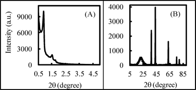 | ||
| Fig. 1 XRD patterns of NiO/SBA-15 (Catalyst no.1). | ||
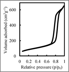
Fig. 2 shows the nitrogen adsorption–desorption isotherm of NiO/SBA-15 with a NiO loading of 10 wt% calcined at 800 °C. The isotherm was similar to the type IV IUPAC classification,41 clearly indicating that these materials possessed mesoporous structures, and a type-H1 hysteresis loop was observed. The isotherm was typical for SBA-15, indicating the formation of a p6mm structure with open cylindrical mesopores. As the NiO loading increased, the nitrogen adsorption–desorption isotherms (not shown here) remained unchanged, and there was no blocking effect, unlike that obtained with the post synthesis method.37,38 This result suggests that NiO particles were dispersed into the SiO2 structure of SBA-15, not in the SBA-15 pores, unlike that prepared by the post synthesis method.
The NiO/SBA-15 characteristics are summarized in Table 1. Although there was no difference in pore size with increased NiO loading, the surface area and pore volume decreased, indicating that the SBA-15 structure was degraded by NiO loading.
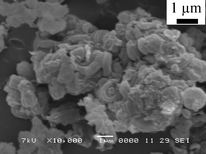
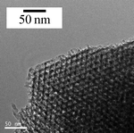
The SEM image in Fig. 3 shows that the SBA-15 morphology consisted of rod-like aggregates, and this is the same as that of typical SBA-15, as in the previous report.40 The TEM image is shown in Fig. 4. It had an ordered mesoporous structure for typical SBA-15. No aggregates of NiO particles were observed, indicating that the NiO particles were highly dispersed into the SBA-15 structure. Therefore, highly loaded and well-dispersed NiO/SBA-15 could be obtained by the direct synthesis method.
3.2 RWGS reaction
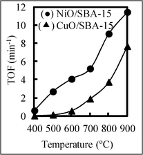
To investigate the influence of catalysts, we performed the RWGS reaction using producer gas from biomass gasification with and without catalysts by fixing the CO2/H2 ratio at 1, and the result is shown in Fig. 5 (A). In Fig. 5 (A), we can see that the RWGS reaction occurred even without a catalyst. Although there was almost no CO2 conversion at temperatures below 600 °C, the CO2 conversion increased with increasing temperature. When catalyst no. 1 with a NiO loading of 10 wt% was employed, the CO2 conversion was enhanced compared with that obtained without catalysts, and it increased with increasing temperature. Therefore, the catalysts played the important role of increasing the CO2 conversion in the RWGS reaction. Because the CO2/H2 ratio in producer gas is often not 1, the influence of the H2/CO2 ratio on CO2 conversion at 800 °C was also investigated and is shown in Fig. 5 (B). CO2 conversion using catalyst no. 1 with a NiO loading of 10 wt% increased as the H2/CO2 ratio increased, indicating that the complete consumption of CO2 was possible at a high H2 concentration (the excess H2 can be recycled after the reaction). These results suggest that high equilibrium conversion can be achieved at a high temperature and a high H2/CO2 ratio, indicating that a high temperature and H2/CO2 ratio can shift the equilibrium in the RWGS reaction to the right. The CO2 conversion at 900 °C was very high compared with that in other reports.24–33 Also, to confirm this conclusion, we used 1 wt% NiO/SBA-15 and CuO/SBA-15 as a catalyst to investigate the RWGS reaction, and the result is shown in Fig. 6. The turnover frequency (TOF) using NiO/SBA-15 was greater than that using CuO/SBA-15. Therefore, the catalytic activity of NiO/SBA-15 was higher than that using the commonly employed CuO/SBA-15.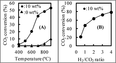 | ||
Fig. 5 Using NiO/SBA-15 with different NiO loading, (A) CO2 conversion at different temperature (CO2![[thin space (1/6-em)]](https://www.rsc.org/images/entities/char_2009.gif) :H2 = 60:60 ml min−1) and (B) with H2/CO2 ratio (CO2:H2 = 60:X ml min−1) at 800 °C. :H2 = 60:60 ml min−1) and (B) with H2/CO2 ratio (CO2:H2 = 60:X ml min−1) at 800 °C. | ||
Although there was no difference in the CO2 conversion when the NiO loading of 10 wt% was increased to 40 wt% at a high temperature of over 600 °C, suggesting that the RWGS reaction achieved equilibrium, at a low temperature of 500 °C, the CO2 conversion seemed to increase as the NiO loading increased. The CO selectivity when using NiO/SBA-15 with different NiO loadings at different temperatures is shown in Fig. 7. With an NiO loading of 10 wt%, the CO selectivity was 100%, regardless of temperature. When the NiO loading exceeded 20 wt%, the CO selectivity was 100% at a temperature of over 600 °C, regardless of NiO loading. In contrast, the CO selectivity was not 100% due to the formation of CH4 at temperatures below 500 °C, indicating that the NiO loading affects the CO selectivity at low reaction temperatures. The CO selectivity seemed to decrease as the NiO loading increased at low temperature. Therefore, to obtain CO with a selectivity of 100%, the RWGS reaction should be carried out at a suitable temperature and using NiO/SBA-15 with an appropriate NiO loading as a catalyst. In other words, the temperature and NiO loading were important factors influencing CO selectivity.
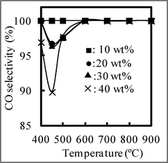 | ||
| Fig. 7 CO selectivity at different temperature using NiO/SBA-15 with different NiO loading. CO2:H2 = 60:60 ml min−1. | ||
A TEM image shows that the NiO particles were well dispersed into SBA-15. When the NiO loading was low (10 wt%), the NiO particles may have been completely dispersed into individual NiO particles by the SiO2 of SBA-15. Namely, one NiO particle does not exist near another NiO particle in NiO/SBA-15. However, as the NiO loading increased, the environment surrounding the NiO particles began to change, and one or more NiO particles appeared in close proximity to other NiO particles. In accordance with a previous report,39 the mechanism of CO2 methanation over Ni/SBA-15 was considered and is shown in Fig. 8. In the CO2 adsorption step on the Ni surface, two active Ni particles (paired Ni–Ni) are required, and then CO2 methanation can occur to form CH4 and CO as a by-product. In other words, when only one active metallic Ni (single active Ni particle) was present, CO2 methanation cannot occur. Therefore, we can explain why the NiO loading affects the CO selectivity at a low reaction temperature. As shown in Fig. 9, with a low NiO loading of 10 wt%, because only a single (isolated) Ni particle was present, only the RWGS reaction occurred. Therefore, CO2 methanation cannot be catalyzed, so no CH4 is formed. When the NiO loading is increased above 20 wt%, paired Ni–Ni particles began to appear, so the CO2 methanation occurred in addition to the RWGS reaction, resulting in CO + CH4 formation. Namely, CO was formed by two reactions (CO as the main product from the RWGS reaction, and as a by-product of CO2 methanation). Therefore, the CO2 conversion increased with increasing NiO loading at a low temperature of 500 °C, due to the occurrence of CO2 methanation.
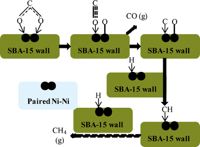 | ||
| Fig. 8 Mechanism of CO2 methanation over Ni/SBA-15. | ||
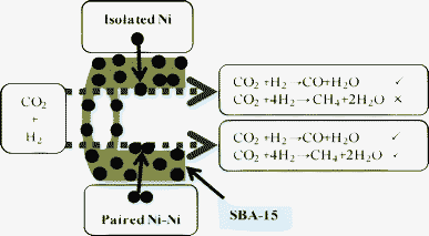 | ||
| Fig. 9 Coordination of Ni particle and its catalyzed reaction. | ||
To validate our above explanation, we employed 10 wt% NiO supported SBA-15 prepared by the post synthesis method as a reference catalyst to investigate the RWGS reaction. SBA-15 was synthesized according to the reported method.42 The starting mixture was prepared as follows: 4 g of Pluronic P123 (P123, EO20PO70EO20, Aldrich, USA) was dissolved in 105 g of deionized water at room temperature, followed by 8.52 g of tetraethylorthosilicate (Si(OC2H5)4, TEOS, Wako Chemical, Japan, 95.0%). The mixture was then stirred for 30 min and hydrochloric acid (HCl, Wako Chemical, Japan, 35.0–37.0%) was added to obtain the starting synthesis mixture. The obtained starting mixture was aged immediately at 60 °C for 24 h under reflux conditions. The chemical composition of the prepared starting mixture was as follows: 1.00 TEOS:1.65 × 10⁻² P123:5.00–6.95·HCl:140·H2O. The resulting white solid was filtered, washed thoroughly with deionized water, dried overnight in an oven at 80 °C, and calcined at 550 °C for 10 h. NiO/SBA-15 was prepared by the conventional solvent impregnation (SI) method using ethanol (EtOH, Wako Chemical, Japan, 99.5%) as a solvent: After Ni(NO3)2·6H2O had been completely dissolved in EtOH under ultrasonication, SBA-15 was added and dispersed for 6 h also under ultrasonication, then dried at room temperature and calcined at 400 °C for 5 h.
In this NiO/SBA-15 reference catalyst obtained by the post synthesis method, it can be considered that the NiO particles were occluded in the SBA-15 pores, so quantities of paired NiO particles were present. Namely, the dispersion degree of the reference catalyst was lower than that of NiO/SBA-15 obtained by the direct synthesis method. As shown in Fig. 10 (A), when the reference catalyst was employed, at high temperatures of over 600 °C, the CO2 conversion increased with the increase in temperature, and was lower than that obtained using NiO/SBA-15 synthesized by the direct synthesis method. However, at low temperatures of below 500 °C, because the CO2 methanation (catalyzed by the paired Ni–Ni) occurred, the CO2 conversion was higher than that obtained using NiO/SBA-15 synthesized by the direct synthesis method. The CO selectivity is shown in Fig. 10 (B). Although when using the reference catalyst, the CO selectivity was 100% at temperatures above 700 °C, it was not 100% at temperatures below 600 °C due to the formation of CH4. This differs from the result obtained using NiO/SBA-15 with a NiO loading of over 20 wt% synthesized by the direct synthesis method. When the reference catalyst was used at low temperatures, the CO selectivity (about 60%) was far lower than that obtained using NiO/SBA-15 synthesized by the direct synthesis method due to the difference in the quantity of paired Ni–Ni particles, and in this case, the CH4 selectivity exceeded 40%. Therefore, the CO selectivity was also affected by the catalyst synthesis method. This result further indicates that the paired Ni–Ni catalyzed the CO2 methanation and confirms our above explanation.
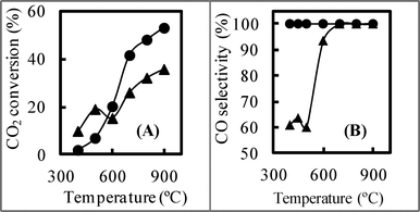 | ||
| Fig. 10 (A) CO2 conversion and (B) CO selectivity using catalyst no. 1 (•) and reference catalyst (▴) at different temperatures. CO2:H2 = 60:60 ml min−1. | ||
4 Conclusions
In summary, well-dispersed NiO/SBA-15 with a high loading could be obtained by the direct synthesis method. The obtained NiO/SBA-15 catalysts exhibited excellent efficiency, and selectivity with regards to reducing CO2 in a producer gas to CO by the RWGS reaction. The CO2 conversion increased as the temperature and H2/CO2 ratio increased, indicating that a high temperature and a high H2/CO2 ratio favors CO2 conversion. The CO selectivity was affected by the NiO loading and synthesis method. This can be explained by the fact that a single (isolated) Ni particle catalyzes the RWGS reaction, giving a high selectivity of 100% for reducing CO2 to CO. The paired Ni–Ni particles catalyze CO2 methanation, giving a low selectivity of less than 100% for reducing CO2 to CO due to CH4 formation.References
- A. Varma and B. Behera, Green Energy: Biomass Processing and Technology, Capital Publishing Company, New Delhi, 2003 Search PubMed.
- G. W. Huber, S. Iborra and A. Corma, Chem. Rev., 2006, 106, 4044–4098 CrossRef CAS.
- M. M. Yung, W. S. Jablonski and K. A. Magrini-Bair, Energy Fuels, 2009, 23, 1874–1883 CrossRef CAS.
- M. J. Antal, S. G. Allen, D. Schulman and X.-D. Xu, Ind. Eng. Chem. Res., 2000, 39, 4040–4053 CrossRef CAS.
- X.-H. Hao, L.-J. Guo, X.-M. Zhang and Y. Guan, Chem. Eng. J., 2005, 110, 57–65 CrossRef CAS.
- I.-G. Lee, M.-S. Kim and S. K. Ihm, Ind. Eng. Chem. Res., 2002, 41, 1182–1188 CrossRef CAS.
- X. H. Hao, L. J. Guo, X. A. Mao, X. M. Zhang and X.-J. Chen, Int. J. Hydrogen Energy, 2003, 28, 55–64 CrossRef CAS.
- A. Sınag, A. Kruse and V. Schwarzkopf, Ind. Eng. Chem. Res., 2003, 42, 3516–3521 CrossRef.
- A. J. Byrd, K. K. Pant and R. B. Gupta, Ind. Eng. Chem. Res., 2007, 46, 3574–3579 CrossRef CAS.
- Y.-J. Lu, L.-J. Guo, C.-M. Ji, X. M. Zhang, X. H. Hao and Q. H. Yan, Int. J. Hydrogen Energy, 2006, 31, 822–831 CrossRef CAS.
- J. M. Fox III, Catal. Rev. Sci. Eng., 1993, 35, 169–212 Search PubMed.
- J.-R. Rostrup-Nielsen and J.-H. Bak-Hansen, J. Catal., 1993, 144, 38–49 CrossRef CAS.
- A.T. Ashcroft, A. K. Cheetham, M. L. H. Green and P. D. F. Vernon, Nature, 1991, 352, 225–226 CrossRef CAS.
- M. C. Seemann, T. J. Schildhauer, S. M. A. Biollaz, S. Stucki and A. Wokaun, Appl. Catal., A, 2006, 313, 14–21 CrossRef CAS.
- J. Kopyscinski, T. J. Schildhauer and S. M. A. Biollaz, Chem. Eng. Technol., 2009, 32, 343–347 CrossRef CAS.
- J. Kopyscinski, T. J. Schildhauer and S. M. A. Biollaz, Fuel, 2010, 89, 1763–1783 CrossRef CAS.
- M. C. Seemann, T. J. Schildhauer and S. M. A. Biollaz, Ind. Eng. Chem. Res., 2010, 49, 7034–7038 CrossRef CAS.
- P. G. Jessop, F. Joo and C.-C. Tai, Coord. Chem. Rev., 2004, 248, 2425–2442 CrossRef CAS.
- T. Sakakura, J.-C. Choi and H. Yasuda, Chem. Rev., 2007, 107, 2365–2387 CrossRef CAS.
- G. Centi and S. Perathoner, Catal. Today, 2009, 148, 191–205 CrossRef CAS.
- M. Bourrez, F. Molton, S. Chardon-Noblat and A. Deronzier, Angew. Chem., Int. Ed., 2011, 50, 9903–9906 CrossRef CAS.
- C. Federsel, R. Jackstell and M. Beller, Angew. Chem., Int. Ed., 2010, 49, 6254–6257 CrossRef CAS.
- M. Mikkelsen, M. Jorgensen and F. C. Krebs, Energy Environ. Sci., 2010, 3, 43–81 CAS.
- C. S. Chen, W. H. Cheng and S. S. Lin, Catal. Lett., 2000, 68, 45–48 CrossRef CAS.
- C. S. Chen, W. H. Cheng and S. S. Lin, Catal. Lett., 2002, 83, 121–126 CrossRef CAS.
- C. S. Chen, W. H. Cheng and S. S. Lin, Appl. Catal., A, 2003, 238, 55–67 CrossRef CAS.
- C. S. Chen, W. H. Cheng and S. S. Lin, Appl. Catal., A, 2004, 257, 97–106 CrossRef CAS.
- F. S. Stone and D. Waller, Top. Catal., 2003, 22, 305–318 CrossRef CAS.
- A. Goguet, F. Meunier and J. P. Breen, J. Catal., 2004, 226, 382–392 CrossRef CAS.
- A. Goguet, F. C. Meunier and D. Tibiletti, J. Phys. Chem. B, 2004, 108, 20240–20246 CrossRef CAS.
- D. Tibiletti, A. Goguet, F. C. Meunier, J. P. Breen and R. Burch, Chem. Commun., 2004, 1636–1637 RSC.
- X. Wu, Q. Liang and D. Weng, J. Rare Earths, 2006, 24, 549–553 CrossRef.
- K. Li, X. Wang, Z. Zhou, X. Wu and D. Weng, J. Rare Earths, 2007, 25, 6–9 CrossRef.
- L. Wang, S. Zhang and Y. Liu, J. Rare Earths, 2008, 26, 66–70 CrossRef.
- D. Zhao, J. Feng, Q. Huo, N. Melosh, G. H. Fredrickson, B. F. Chmelka and G. D. Stuchy, Science, 1998, 279, 548–552 CrossRef CAS.
- D. Zhao, Q. Huo, J. Feng, B. F. Chmelka and G. D. Stuchy, J. Am. Chem. Soc., 1998, 120, 6024–6036 CrossRef CAS.
- M.-Y. Cheng, C.-J. Pan and B.-J. Hwang, J. Mater. Chem., 2009, 19, 5193–5200 RSC.
- L. Vradman, M. V. Landau, D. Kantorovich, Y. Koltypin and A. Gedanken, Microporous Mesoporous Mater., 2005, 79, 307–318 CrossRef CAS.
- G. D. Weatherbee and C. H. Bartholomew, J. Catal., 1982, 50, 460–472 CrossRef.
- B.-W. Lu and K. Kawamoto, Mater.Sci.Bull., 2012, 47, 1301–1305 CrossRef CAS.
- S. J. Gregg and K. S. W. Sing, Adsorption Surface Area and Porosity, Academic Press, New York, 1982 Search PubMed.
- B.-W. Lu, Y. Inagi and A. Endo, J. Nanosci. Nanotechnol., 2011, 11, 2361–2367 CrossRef CAS.
| This journal is © The Royal Society of Chemistry 2012 |