DOI:
10.1039/C2RA20270K
(Paper)
RSC Adv., 2012,
2, 5234-5242
The adsorption of phosphate by graphene from aqueous solution
Received
15th February 2012
, Accepted 27th March 2012
First published on 29th March 2012
Abstract
Graphene was prepared by a facile liquid phase exfoliation and characterized by Raman spectroscopy, Fourier transform infrared spectroscopy, powder X-ray diffraction, scanning electron microscopy and zeta potential measurements. A systematic study of the adsorption process was performed by varying pH, ionic strength and temperature. The experimental results showed that graphene is an excellent phosphate adsorbent with an adsorption capacity of up to 89.37 mg g−1 at an initial phosphate concentration of 100 mg L−1 and temperature of 303 K. The adsorption kinetics was modeled by first and second order rate, Elovich and Weber and Morris intraparticle diffusion models. The rate constants for all of these kinetic models were calculated and the results indicate that the second order kinetics model was well-suited to model the kinetic adsorption of phosphate. The Langmuir, Freundlich and D–R isotherm models were applied to describe the equilibrium isotherms and the isotherm constants were determined. Equilibrium data were well-described by the typical Langmuir adsorption isotherm. Thermodynamic studies revealed that the adsorption reaction was a spontaneous and endothermic process.
1. Introduction
Phosphate is found in water streams due to anthropogenic activities or geochemical processes. It is an essential nutrient for growth of microorganisms and, thus, the presence of phosphate anion concentrations exceeding about 2 μM in water reservoirs are known to stimulate algal growth (eutrophication), reducing the dissolved oxygen in the aqueous environment, which not only kills the aquatic life, but also disrupts the natural food chain and also leads to deterioration of water quality. Hence, more attention has been devoted toward the reduction of phosphate levels in water streams as a consequence of severe legislation that has been adopted in many countries.1,2 According to WHO, the allowable limit of phosphate in drinking water is 5.0 mg L−1 and the RDA (Recommended Daily Allowance) should not exceed 800 mg3 and the superfluous phosphate should be removed from drinking water. So, it is imperative and significant to explore suitable techniques to remove excessive phosphate from water. The phosphate in water can be removed by many methods viz., chemical precipitation, adsorption, biological materials, membrane processes, ion exchange and crystallization.4 The main disadvantage of chemical precipitation is the generation of unwanted chemicals and waste disposal issues. The disadvantages of membrane processes are low economic viability, high maintenance cost, fouling, scaling and membrane degradation. In a biological treatment plant, it is necessary to transfer phosphate from the liquid to the sludge phase and the removal efficiency usually does not exceed 30%, which means that remaining phosphate should be removed by another technique.5–9 Adsorption is a widely accepted technology for both organic and inorganic contaminants,10–18 in particular, it is more effective in reducing phosphate concentrations to a permissible value than the other methods. Additionally, adsorption is considered a fast and inexpensive purification method.19–23 Among all of the adsorbents, carbon is a versatile adsorbent that is heavily used in the removal of various pollutants, including heavy metals from aqueous solutions.24–29 Various forms of carbon and their composites have been investigated to improve the adsorption efficacy.30–32 Graphene,33 the latest member of the carbon family, is believed to be one of the most interesting materials of this century. Graphene and its composites offer utility in several applications due to its unique two-dimensional nature and associated band structure.34–36 It has drawn much scientific attention since its discovery due to its unique electronic37–39 and mechanical properties,39 specific magnetism,40 excellent mobility of charge carriers41 and high thermal conductivity.42 Most of these composites were proposed either for catalytic or electronic applications.43 The most important and widely used application of bulk carbon is in environmental remediation.44,45 However, up to now, not much investigation has been carried on utilizing graphene as an adsorbent to remove phosphate from aqueous solution.
In this study, the phosphate adsorption properties of graphene were studied through investigating experimental parameters, such as pH, concentration and temperature. Adsorption isotherm, kinetic and thermodynamic parameters were estimated from the experimental results.
2. Experimental
2.1. Preparation and characterization of graphene
Graphene was prepared by a facile liquid phase exfoliation of worm-like graphite as described elsewhere.46 In brief, natural graphite flakes were dispersed into a mixture (20![[thin space (1/6-em)]](https://www.rsc.org/images/entities/char_2009.gif) :1 by volume) of concentrated sulfuric acid (98 wt%) and hydrogen peroxide (30 wt%). The mixture was stirred for 1 h and washed with deionized water. The mixture was then dried at 100 °C for 24 h to obtain graphite intercalation compounds. The graphite intercalation compounds were heated at 900 °C for 10 s. The decomposition of the intercalating acid leads to a dramatic increase in the dimension perpendicular to the graphite sheets (worm-like graphite). The worm-like graphite was subjected to a final exfoliation to obtain a monolayer or a few layers of graphene sheets by ultrasonication and centrifugation of a 1-methyl-2-pyrrolidinone (NMP) suspension (0.1 mg mL−1) of the sample. The top half of the dispersion was heated at 200 °C to remove NMP for further use.
:1 by volume) of concentrated sulfuric acid (98 wt%) and hydrogen peroxide (30 wt%). The mixture was stirred for 1 h and washed with deionized water. The mixture was then dried at 100 °C for 24 h to obtain graphite intercalation compounds. The graphite intercalation compounds were heated at 900 °C for 10 s. The decomposition of the intercalating acid leads to a dramatic increase in the dimension perpendicular to the graphite sheets (worm-like graphite). The worm-like graphite was subjected to a final exfoliation to obtain a monolayer or a few layers of graphene sheets by ultrasonication and centrifugation of a 1-methyl-2-pyrrolidinone (NMP) suspension (0.1 mg mL−1) of the sample. The top half of the dispersion was heated at 200 °C to remove NMP for further use.
The morphology and structure of graphene was characterized by SEM (Hitachi model s-3000 h, Japan). The FTIR spectrum of graphene was recorded with a FTIR spectrometer (Nexus 670, USA). Raman spectroscopy was performed with a Renishaw InVia Laser Raman Microscope. The X-ray diffraction (XRD) pattern of graphene was analyzed using an X′per PRO X-ray diffractometer (PANalytical, USA). The thickness of graphene was conducted with tapping mode atom force microscopy (AFM, SPA-400 SPM unit from Seiko, Japan).
2.2. Reagents and measurements
Sodium phosphate (NaH2PO4) (Analar Reagent) was dissolved in distilled water for the required concentration (25–125 mg L−1) and used for further experiment. The pH of the solution was adjusted to a desired value using appropriate concentrations of HNO3 or NaOH solutions. Phosphate was measured using an Ion Chromatograph (Metrohm AG, Herisau, Switzerland) equipped with a Dual 3 column (250 mm × 4 mm), a RP guard column and a conductivity detector. NaOH (5 mM) served as the eluent and sulfuric acid (2.0 mM) as the regenerant in the chromatogram analysis. All chemicals were purchased in analytical purity and used in the experiments directly without any further purification. All solutions were prepared using Milli-Q water.
2.3. Batch mode adsorption experiment
Batch adsorption experiments were performed using 100 mL glass bottles with addition of 0.05 g of graphene and 75 mL of phosphate solution of concentration from 25–125 mg L−1. The glass bottles were sealed with Teflon and then were placed on a shaker. The adsorption experiments were carried out at 180 rpm for 12 h (25 °C). The temperature of the solution was controlled to the desired value with a variation of ±2 K by adjusting the rate of flow of thermostatically controlled water through an external glass-cooling spiral. All of the experiments were repeated three times for reproducibility and the accuracy of the results are ±1%. Zeta potential of graphene was measured by a Malvern zetameter (Zetasizer 2000).
3. Result and discussion
3.1. Characterizations of graphene
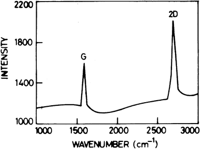
The Raman spectrum of graphene is shown in Fig. 1. Raman spectroscopy is a fast, non-destructive and unambiguous technique to study carbonaceous materials. The Raman spectrum of graphene is very sensitive to the number of atomic layers and the presence of disorder or defects, which allows for accurate graphene characterization.47
The clear band at around 1583 cm−1 is generally assigned as the G band. The G band is associated with the vibration of sp2 carbon atoms in a graphitic 2D hexagonal lattice. The single and sharp 2D peak appears at 2688 cm−1. The higher intensity of the 2D peak than the G peak indicates that the sample prepared by this method is graphene. The weak and broad 2D peak at 2688 cm−1 is indication of disorder due to an out of plane vibration mode. Both of the G and 2D peaks are similar to the results from previous papers.48,49
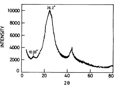
XRD measurements were employed to investigate the phase and structure of the synthesized samples. As shown in Fig. 2, the diffraction peak at 2θ = 26.2°, corresponding to the normal graphite spacing (002) of the graphite plane, disappeared in the synthesized graphene in the oxidation process. The broad and relatively weak diffraction peak at 2θ = 10.03° corresponding to the typical diffraction peak of graphene is attributed to the (002) plane.
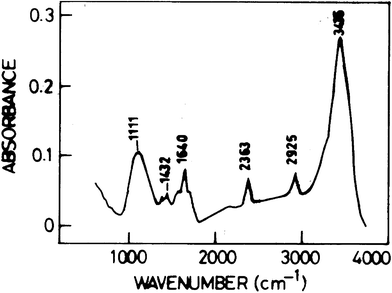
Fig. 3 shows the FT-IR spectrum of graphene. The bands at 1432 cm−1 and 1111 cm−1 can be attributed to the appearance of CH2 and C–N groups, which are possibly introduced on the surface of graphene by 1-methyl-2-pyrrolidinone treatment. The band at 1640 cm−1 can be attributed to stretching mode of amide type C![[double bond, length as m-dash]](https://www.rsc.org/images/entities/char_e001.gif) O bond introduced by sulfuric acid and hydrogen peroxide (oxidation reagent). The bands at 2925 cm−1 and 2363 cm−1 are associated with the stretching of CH2 and CH3 groups from the organic solvent of 1-methyl-2-pyrrolidinone. The band at wave number of 3435 cm−1 is indicative of the appearance of the stretching of A–OH.
O bond introduced by sulfuric acid and hydrogen peroxide (oxidation reagent). The bands at 2925 cm−1 and 2363 cm−1 are associated with the stretching of CH2 and CH3 groups from the organic solvent of 1-methyl-2-pyrrolidinone. The band at wave number of 3435 cm−1 is indicative of the appearance of the stretching of A–OH.
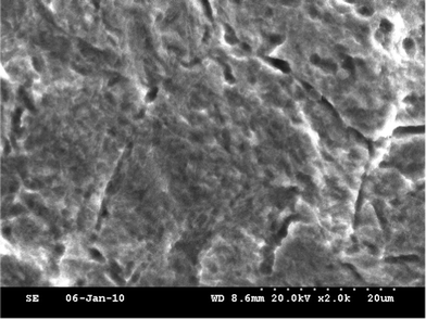
Fig. 4 shows the SEM images of the synthesized graphene. The SEM image shows that the graphene partially transparent with dimensions ranging from ten or more micrometers. The image also suggests some layered graphene shape, although the SEM image does not deduce the layer numbers of the synthesized graphene exactly. It can be seen from the AFM image (image not shown) that the thickness of graphene is about 2.98 nm.
Point of Zero Charge (PZC) was determined for prepared graphene; the results show that the PZC is 5.1 (figure not shown). PZC can be used to explain the effect of pH on ions adsorption. When pH = PZC, the surface charge of adsorbents is neutral; it is negligible of the electrostatic force between ions and surface of adsorbents. When pH > or < PZC, this balance is broken. When pH < PZC, the surface charge of adsorbents is positive, so adsorbents have a positive surface. There is an electrostatic repulsion between ions and this positive surface, which results in low sorption. When pH > PZC, the surface charge of adsorbents is negative, the surface of adsorbents is negative too, so metal ions in solution are attracted to this surface.
3.2. Effect of pH
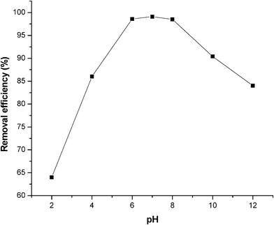
Electrolyte pH is one of the most important parameters controlling the ion sorption process. To examine this effect, a series of experiments were carried out using 100 mg L−1 phosphate containing solutions, with an initial pH varying in the range 2–12 and the results are presented in Fig. 5. The optimum phosphate adsorption was observed at pH range 6.0–8.0. As the pH increased beyond 8, the adsorption of phosphate by graphene was decreased. The low adsorption of phosphate at higher pH might be due to the electrostatic repulsion of phosphate by the negatively charged graphene surface at high pH. The adsorption capacity increases with pH in the acidic range and reaches the maximum removal efficiency of 99.1% at pH 7.0.
Anionic contaminants are proposed to be adsorbed on adsorbents through specific and/or non-specific adsorption.50,51 The specific adsorption involves ligand exchange reactions (where the anions displace OH groups from the surface).50 The non-specific adsorption involves the coulombic forces (mainly depends on the PZC/IEP of the adsorbent).51 The non-specific adsorption indicates that the phosphate adsorption capacity of an adsorbent decreases at pH ≥ PZC/IEP due to the neutrally or negatively charged surface of the adsorbent. However, the experimental result shows that the best phosphate adsorption occurs at pH 7.0, which is much higher than the PZC of graphene (PZC of graphene = 5.1). This means that the adsorption takes place even though the surface is electrically negative. The phenomenon suggests that adsorption of phosphate by graphene is mainly a specific process.
3.3. Effect of temperature
The effect of temperature for an adsorption of phosphate on graphene was investigated at four different temperatures (303, 313, 323 and 333 K). Fig. 6 illustrates the variation of phosphate concentration with time at the four different temperatures. The figure shows that adsorption rapidly increased in the first 10 min, after which adsorption slowly approached equilibrium. The adsorption reached equilibrium within 10 min. It is also found that the sorption of phosphate increases with an increase in temperature, indicating that phosphate removal by adsorption to graphene was favorable at higher temperatures. Since the sorption capacity of the adsorbent increased with temperature, it can also be said that the sorption was an endothermic process. Also with the increase of temperature, the interaction forces between the solute and the solvent become weaker than those between solute and adsorbent. As a consequence, the solute is easier to adsorb. Table 1 reveals the increase in adsorption with an increase in phosphate concentration at different temperature at equilibrium time. The adsorption capacity increases from 89.37 to 92.36 mg g−1 at a phosphate equilibrium concentration of 100 mg L−1, as the temperature rises from 303 to 343 K.
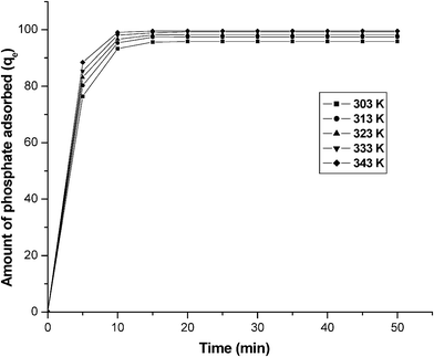 |
| | Fig. 6 The effect of time on the amount of phosphate adsorbed (qe) at various temperatures. Conditions: concentration = 100 mg L−1; pH = 7.0. | |
Table 1 Amount of phosphate adsorbed for various phosphate concentrations at different temperatures at equilibrium time and pH 7
| Concentration (mg L−1) |
Amount of phosphate adsorbed (mg L−1) |
| |
303 K |
313 K |
323 K |
333 K |
343 K |
| 25 |
21.11 |
21.77 |
21.86 |
22.34 |
22.67 |
| 50 |
46.78 |
46.96 |
47.61 |
47.93 |
48.34 |
| 75 |
68.67 |
68.73 |
68.99 |
69.91 |
71.32 |
| 100 |
89.37 |
89.58 |
90.66 |
91.67 |
92.36 |
| 125 |
116.3 |
116.8 |
117.9 |
119.8 |
121.6 |
3.4. Effect of concentration
In order to evaluate the effect of agitation time initial phosphate concentration, experiments were conducted at varying initial concentrations from 25–125 mg L−1. From Fig. 7, it is clear that the adsorption of phosphate is increased with an increase temperature and remains constant after the equilibrium time. The equilibrium time was 10 min for all of the concentrations studied (25–125 mg L−1).52 The adsorption is rapid in the initial stages and gradually decreases with the progress of adsorption. The plots are single, smooth and continuous curves leading to saturation, suggesting the possible monolayer coverage to nitrate on the surface of the adsorbent.
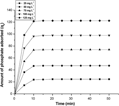 |
| | Fig. 7 The effect of agitation time and initial concentration of phosphate for the adsorption of phosphate on graphene. Conditions: concentration = 100 mg L−1; pH = 7.0. | |
3.5. Kinetic modeling
In order to establish the kinetics of phosphate adsorption, the adsorption kinetics of graphene was investigated using first order, second order kinetic models, Elovich and intraparticle diffusion models. In the present investigation, four kinetic models, namely, pseudo first order, pseudo second order, Elovich and intraparticle diffusion models were tested to obtain the rate constants, equilibrium adsorption capacity and adsorption mechanism at different concentrations.53
3.5.1. First order Lagergren model.
The first order Lagergren model is generally expressed as follows:54where qe and qt are the adsorption capacities at equilibrium and at time t (min) respectively, and k1(min−1) is a rate constant of first order adsorption. The integrated form of the above equation with the boundary conditions t = 0 to > 0 (q = 0 to > 0) is rearranged to obtain the following time dependence function:| | | log(qe − qt) = log(qe) − k1t/2.303. | (2) |
The experimental data were analyzed initially with the first order Lagergren model. The plot of log(qe − qt) vs. t should give the linear relationship from which k1 and qe can be determined by the slope and intercept, respectively (eqn (2)). The computed results are presented in Table 2. The results show that the theoretical qe (cal) value doesn't agree with the experimental qe (exp) values at all concentrations studied with a poor correlation co-efficient. So, the experimental data were fitted further with a second order Lagergren model.
Table 2 A comparison between the experimental and calculated qe values for different temperatures in first and second order adsorption isotherms at a phosphate concentration of 100 mg L−1 and pH 7
| Concentration (mg L−1) |
q
e (exp) |
First order adsorption |
Second order adsorption |
|
q
e (cal) |
k
1 × 10⁴ (min mg−1) |
R
2
|
q
e(Cal) |
k
2 × 10⁴ (min mg−1) |
R
2
|
| 25 |
21.11 |
52.93 |
−0.0197 |
0.9456 |
21.06 |
0.0914 |
0.9999 |
| 50 |
46.78 |
66.06 |
−0.0164 |
0.9513 |
46.51 |
0.0805 |
0.9998 |
| 75 |
68.67 |
93.24 |
−0.0115 |
0.9554 |
67.31 |
0.0735 |
0.9997 |
| 100 |
89.37 |
183.6 |
−0.0081 |
0.9467 |
88.41 |
0.0667 |
0.9995 |
| 125 |
116.3 |
195.6 |
−0.0073 |
0.9499 |
115.4 |
0.0645 |
0.9999 |
3.5.2. Second order Lagergren model.
The Lagregren second order kinetic model is expressed as55| | | dqt/dt = k2(qe − qt)2, | (3) |
where k2 is the rate constant of second order adsorption. The integrated form of eqn (3)with the boundary condition t = 0 to > 0 (q = 0 to > 0) is| | | 1/(qe − qt) = 1/qe + k2t. | (4) |
Eqn (4) can be rearranged and linearized as
| | | t/qt = 1/k2qe2 + t/qe, | (5) |
where
qe and
qt are the amount of phosphate adsorbed on
graphene at equilibrium and at time
t (min), respectively, and
k2 is the rate constant for the second order kinetic model.
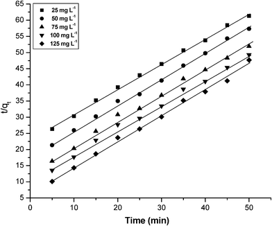
The kinetic data were fitted to the second order Lagergren model (eqn (5)). The equilibrium adsorption capacity, qe(cal) and k2 were determined from the slope and intercept of plot of t/qt versus t (Fig. 8) and are compiled in Table 2. The plots were found to be linear with good correlation coefficients. The theoretical qe(cal) values agree well with the experimental qe(exp) values at all current densities studied. This implies that the second order model is in good agreement with the experimental data and can be used to favorably explain the phosphate adsorption on graphene.
3.5.3. Elovich model.
The Elovich model equation is generally expressed as56The simplified form of Elovich (eqn (6)) is| | | qt = 1/βloge(αβ) + 1/β loge(t), | (7) |
where α is the initial adsorption rate (mg g−1 h) and β is the desorption constant (g mg−1). The Elovich model was tested for the phosphate adsorbed kinetic values. If phosphate adsorption fits the Elovich model (eqn (7)) a plot of qt vs. loge(t) should yield a linear relationship with the slope of (1/β) and an intercept of 1/βloge(αβ). Table 3 depicts the results obtained from the Elovich equation. The lower regression value shows the inapplicability of this model.
Table 3 Elovich model and intraparticle diffusion for different temperatures and pH 7
| Concentration (mg L−1) |
Elovich model |
Intraparticle diffusion |
| |
A (mg g−1 h−1) |
β (g mg−1) |
R
2
|
k
id (l h−1) |
A (%/h) |
R
2
|
| 25 |
7.64 |
45.61 |
0.902 |
30.31 |
0.112 |
0.9546 |
| 50 |
4.94 |
31.33 |
0.931 |
28.63 |
0.141 |
0.9421 |
| 75 |
1.34 |
24.67 |
0.922 |
27.21 |
0.176 |
0.9367 |
| 100 |
0.94 |
16.37 |
0.919 |
23.66 |
0.264 |
0.9468 |
| 125 |
0.54 |
10.31 |
0.926 |
20.61 |
0.299 |
0.9326 |
3.5.4. Weber and Morris intraparticle diffusion model.
The intraparticle diffusion model is expressed as57
A linearized form of the (eqn (8)) is followed by
| | | logR = logkid + alog(t), | (9) |
in which ‘
a’ depicts the adsorption mechanism and
kid may be taken as the rate factor (percent of phosphate adsorbed per unit time).
The intraparticle diffusion was investigated using the empirical relationship based on the model of Weber–Morris (eqn (9)). The plots of qt versus t1/2 should be linear for fitting this model. Lower and higher values of kid illustrate an enhancement in the rate of adsorption and better adsorption with improved bonding between pollutant and the adsorbent particles, respectively. The results are presented in Table 3.
Tables 2 and 3 depict the computed results obtained from first order, second order, Elovich and Weber and Morris intraparticle diffusion. From the tables, it is found that the correlation coefficient decreases from second order, first order, intraparticle diffusion to the Elovich model. This indicates that the adsorption follows the second order model rather than the other models. Furthermore, the calculated qe values agree well with the experimental qe values for the second order kinetics model, concluding that the second order kinetics equation is the best fitting kinetic model.
In this, the widely used Freundlich, Langmuir and D–R isotherm models are applied to simulate and understand the adsorption mechanism of phosphate at different temperatures.
3.6.1. Langmuir isotherm.
The Langmuir model assumes monolayer coverage on the adsorbent.58 The linearized form of the Langmuir adsorption isotherm model is| | | Ce/qe = 1/qmb + Ce/qm | (10) |
where, qe is amount adsorbed at equilibrium concentration Ce, qm is the Langmuir constant representing maximum monolayer adsorption capacity and b is the Langmuir constant related to energy of adsorption. The essential characteristics of the Langmuir isotherm can be expressed as the dimensionless constant RL:where RL is the equilibrium constant and it indicates the type of adsorption, b is the Langmuir constant. Co is various concentrations of phosphate solution. The RL values between 0 and 1 indicate the favorable adsorption. The Langmuir isotherm constants b and qm were calculated from the slope and intercept of the plot between 1/qe and 1/Ce (Fig. 9). The Langmuir model parameters and the statistical fits of the adsorption data to this equation are given in Table 4. As can be seen in Table 4, the high regression coefficient confirmed that the Langmuir isotherm best represented the equilibrium adsorption of phosphate to graphene at different temperatures. The excellent fit of the Langmuir isotherm to the experimental data at all temperatures studied confirmed that the adsorption is monolayer; adsorption of each molecule had equal activation energy and that sorbate–sorbate interaction was negligible. In addition, qm decreased with an increase in temperature. The Langmuir constant (b) also increased with an increase in temperature. Seen overall, the information thus obtained specifies an endothermic nature of the existing process. The monolayer adsorption capacity of graphene for phosphate as obtained from the Langmuir isotherm at 303 K was found to be 13.21 mg g−1.
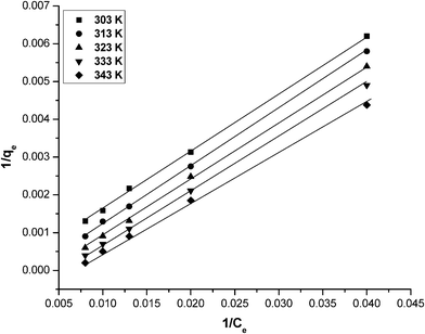 |
| | Fig. 9 A Langmuir plot (1/qevs. 1/Ce) for phosphate adsorption by graphene at different temperatures. Conditions: pH = 7.0; temperature = 303 K and concentration = 25–125 mg L−1. | |
Table 4 Constant parameters and correlation co-efficients calculated for different adsorption isotherm models at different temperatures for phosphate adsorption at 100 mg L−1 at pH 7
| Isotherm |
Temperature |
constants |
| Langmuir |
|
Q
o
|
b
|
R
L
|
R
2
|
| 303 |
13.21 |
0.169 |
0.8997 |
0.9997 |
| 313 |
14.39 |
0.227 |
0.9215 |
0.9998 |
| 323 |
14.52 |
0.268 |
0.8446 |
0.9999 |
| 333 |
16.99 |
0.279 |
0.9067 |
0.9997 |
| 343 |
19.64 |
0.318 |
0.9126 |
0.9996 |
| Freundlich |
|
k
f
|
n
|
|
R
2
|
| 303 |
3.335 |
0.996 |
|
0.9946 |
| 313 |
3.416 |
0.997 |
|
0.9933 |
| 323 |
3.437 |
0.996 |
|
0.9945 |
| 333 |
3.499 |
1.011 |
|
0.9941 |
| 343 |
3.536 |
1.124 |
|
0.9937 |
| D–R |
|
Q
s (× 103 mol g−1) |
B (× 103 mol2 K J−2) |
E (KJ/mol) |
R
2
|
| 303 |
2.233 |
1.423 |
9.78 |
0.8954 |
| 313 |
2.264 |
1.457 |
10.01 |
0.8657 |
| 323 |
2.312 |
1.466 |
10.56 |
0.8789 |
| 333 |
2.399 |
1.478 |
10.94 |
0.8577 |
| 343 |
2.402 |
1.499 |
11.54 |
0.8595 |
3.6.2. Freundlich isotherm.
The Freundlich model is an empirical model allowing for multilayer adsorption on adsorbent.59 The linearized in logarithmic form and the Freundlich constants can be expressed as| | | logqe = logkf + nlogCe, | (2) |
where kf is the Freundlich constant related to adsorption capacity, n is the energy or intensity of adsorption and Ce is the equilibrium concentration of phosphate (mg L−1). The values of kf and 1/n obtained from the intercept and slope of the plot of logqeversus logCe , along with the error functions at all temperatures, are shown in Table 4. The values of 1/n were less than unity, suggesting that phosphate was adsorbed favorably by graphene at all temperatures studied. The increase in Freundlich constants with an increase of temperature confirmed that adsorption was favorable at high temperatures and the process was endothermic in nature. However, the values of the error functions were higher than the Langmuir isotherm values suggesting that the Freundlich model did not fit the experimental data.
3.6.3. Dubinin–Radushkevich isotherm.
Dubinin–Radushkevich isotherm assumes that the characteristic sorption curve is related to the porous structure of the sorbent and apparent energy of adsorption. This model is given bywhere ε is the Polanyi potential, equal to RTln(1 + 1/Ce), B is related to the free energy of sorption and qs is the Dubinin–Radushkevich (D–R) isotherm constant.60 The linearized form is| | | lnqe = ln qs − 2BRTln(1 + 1/Ce) | (14) |
The constant B gives the mean free energy of adsorption per molecule of the adsorbate when it is transferred from the solid from infinity in the solution and the relation is given as
The D–R model, which does not assume a homogeneous surface or a constant adsorption potential as the Langmuir model, was also used to test the experimental data. It was applied to distinguish between physical and chemical adsorption of phosphate. The plots between lnqe and ε2 gave straight lines at all temperatures (figure not shown). The values of constants qe and B thus obtained, along with the error functions, are given in Table 4. The value of the coefficient of determination was much lower than those of the other two isotherms at all studied temperatures. Therefore, in all of the cases, the D–R equation represented the least fit to experimental data than the other isotherm equations. The constant B gives an idea of the mean sorption energy, E, which is defined as the free energy transfer of 1 mol of solute from infinity of the surface of the sorbent and can be calculated using the relationship in eqn (15). The magnitude of E was higher than 8.0 kJ mol−1 for all temperatures studied, indicating that the adsorption mechanism was chemical ion exchange.
Table 4 shows that the adsorption of phosphate ions onto graphene had a high coefficient of determination for the Langmuir isotherm. The dimensionless constant RL were calculated from eqn (9). The RL values were found to be between 0 and 1 for all of the concentrations of phosphate at various temperatures.
3.7. Thermodynamic parameters
Thermodynamic behavior of adsorption of phosphate on graphene was evaluated by the thermodynamic parameters viz., Gibbs free energy change (ΔG0), enthalpy (ΔH0), and entropy (ΔS0).61 These parameters were calculated using the following equations:| |  | (18) |
where ko is the constant of the equation (g mg−1 min−1), E is the energy of activation (J mol−1), Kc is the equilibrium constant, R is the gas constant and T is the temperature in K. Fig. 10 shows that the rate constants vary with temperature according to eqn (16). The activation energy (9.457 kJ mol−1) is calculated from slope of the fitted equation. The free energy change is obtained from eqn (17). The Kc and ΔG values are presented in Table 5. From the table, it is found that the negative value of ΔG indicates the spontaneous nature of adsorption. The enthalpy change (ΔH = 15.67 J mol−1) and entropy change (ΔS = 20.98 J mol−1 K−1) were obtained from the slope and intercept of the van't Hoff linear plots of lnkcversus 1/T (Fig. 11) (eqn (18)). A positive value of enthalpy change (ΔH) indicates that the adsorption process is endothermic in nature and the negative value of change in internal energy (ΔG) show the spontaneous adsorption of phosphate on the adsorbent. Positive values of entropy change show the increased randomness of the solution interface during the adsorption of phosphate on the adsorbent (Table 5).62 Enhancement of the adsorption capacity of coagulant (graphene) at higher temperatures may be attributed to the enlargement of pore size and/or activation of the adsorbent surface.
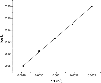 |
| | Fig. 10 A plot of logk2 and 1/T. Conditions: pH = 7.0 and concentration = 100 mg L−1. | |
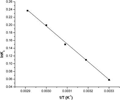 |
| | Fig. 11 A plot of lnKc and 1/T. Conditions: pH = 7.0 and concentration = 100 mg L−1. | |
Table 5 Thermodynamic parameters for the adsorption of phosphate
|
T/K |
K
c
|
ΔGo (kJ mol−1) |
ΔHo (kJ mol−1) |
ΔSo (J mol−1 K) |
| 303 |
0.0067 |
−41.36 |
|
|
| 313 |
0.1164 |
−144.49 |
|
|
| 323 |
0.2267 |
−426.26 |
|
|
| 333 |
0.4178 |
−1147.88 |
15.67 |
20.98 |
| 343 |
0.8978 |
−1767.39 |
|
|
4. Conclusions
The results obtained in this study show that graphene is an effective adsorbent for adsorption/removal of phosphate from aqueous solution. The adsorption process follows second order kinetics, suggesting that the adsorption was a chemical controlling process. The adsorption of phosphate preferably fitting the Langmuir adsorption isotherm suggests monolayer coverage of adsorbed molecules. Thermodynamic investigations indicated that the adsorption reaction was a spontaneous, endothermic and irreversible process.
Acknowledgements
The authors are also grateful to the Director, Central Electrochemical Research Institute, Karaikudi, for publishing this article.
References
- X. Huang, X. Liao and B. Shi, Adsorption removal of phosphate in industrial wastewater by using metal-loaded skin split waste., J. Hazard. Mater., 2009, 166, 1261–1265 CrossRef CAS.
- S. Mustafa, M. I. Zaman and S. Khan, Temperature effect on the mechanism of phosphate anions sorption by MnO2, Chem. Eng. J., 2008, 141, 51–57 CrossRef CAS.
-
WHO (World Health Organisation), Guidelines for Drinking Water Quality, 4th ed., WHO, Geneva, 2011 Search PubMed.
- K. A. Krishnan and A. Haridas, Removal of phosphate from aqueous solutions and sewage using natural and surface modified coir pith., J. Hazard. Mater., 2008, 152, 527–535 CrossRef CAS.
- S. Yeoman, T. Stephenson, J. N. Lester and R. Perry, The removal of phosphorus during wastewater treatment: a review, Environ. Pollut., 1988, 49, 183–233 CrossRef CAS.
- J. P. Boisvert, T. C. To, A. Berrak and C. Jolicoeur, Phosphate adsorption in flocculation processes of aluminium sulphate and polyaluminium–silicate–sulphate, Water Res., 1997, 31, 1939–1946 CrossRef CAS.
- K. Fytianos, E. Voudrias and N. Raikos, Modelling of phosphorus removal from aqueous and wastewater samples using ferric iron, Environ. Pollut., 1998, 101, 123–130 CrossRef CAS.
- R. D. Neufeld and G. Thodos, Removal of orthophosphates from aqueous solutions with activated alumina, Environ. Sci. Technol., 1969, 3, 661–667 CrossRef CAS.
-
H. D. Stensel, Principles of biological phosphorus removal: Phosphorus and Nitrogen Removal from Municipal Wastewater—Principles and Practice, H. K. Lewis, London, 1991, p. 101 Search PubMed.
- V. K. Gupta and A. Rastogi, Equilibrium and kinetic modeling of cadmium (II) biosorption by nonliving algal biomass Oedogonium sp. from aqueous phase, J. Hazard. Mater, 2008, 153, 759–766 CrossRef CAS.
- V. K. Gupta, I. Ali and V. K. Saini, Adsorption studies on the removal of Vertigo Blue49 Orange DNA13 from aqueous solutions using carbon slurry developed from a waste material, J. Colloid Interface Sci., 2007, 315, 87–93 CrossRef CAS.
- V. K. Gupta, A. Mittal, R. Jain, M. Mathur and S. Sikarwar, Photochemical degradation of hazardous dye Safaranin-T using TiO2 catalyst, J. Colloid Interface Sci., 2007, 309, 464–469 CrossRef CAS.
- V. K. Gupta, A. Mittal and L. Krishnan, Jyoti Mittal, Removal and recovery of the hazardous azo dye, acid orange 7, through adsorption over waste materials – bottom ash and de-oiled soya, Ind. Eng. Chem. Res., 2006, 45, 1446–1453 CrossRef CAS.
- V. K. Gupta, R. Jain and S. Varshney, removal of Reactofix golden yellow 3 RFN from aqueous solution using wheat husk – an agricultural waste, J. Hazard. Mater., 2007, 142, 443–448 CrossRef CAS.
- V. K. Gupta, A. Rastogi, M. K. Dwivedi and D. Mohan, Process Development for the removal of zinc and cadmium from wastewater using slag – a blast-furnace waste material, Sep. Sci. Technol., 1997, 32, 2883–2912 CrossRef CAS.
- V. K. Gupta, A. Mittal, L. Kurup and J. Mittal, Adsorption of a hazardous dye, erythrosine, over hen feathers, J. Colloid Interface Sci., 2006, 304, 52–57 CrossRef CAS.
- V. K. Gupta and A. Rastogi, Biosorption of hexavalent chromium by raw and acid-treated green alga Oedogonium hatei from aqueous solutions, J. Hazard. Mater., 2009, 163, 396–402 CrossRef CAS.
- V. K. Gupta, A. Rastogi and A. Nayak, Adsorption studies on the removal of hexavalent chromium from aqueous solution using a low cost fertilizer industry waste material, J. Colloid Interface Sci., 2010, 342, 135–141 CrossRef CAS.
- K. Kuzawa, Y. J. Jung, Y. Kiso, T. Yamada, M. Nagai and T. g. Lee, Phosphate removal and recovery with a synthetic hydrotalcite as an adsorbent, Chemosphere, 2006, 62, 45–52 CrossRef CAS.
- C. Namasivayam and D. Sangeetha, Equilibrium and kinetic studies of adsorption of phosphate onto ZnCl2 activated coir pith carbon, J. Colloid Interface Sci., 2004, 280, 359–366 CrossRef CAS.
- E. Oguz, Removal of phosphate from aqueous Solution with blast furnace slag, J. Hazard. Mater., 2004, 114, 131–137 CrossRef CAS.
- L. Zeng, X. Li and J. Liu, Adsorptive removal of phosphate from aqueous solutions using iron oxide tailings., Water Res., 2004, 38, 1318–1328 CrossRef CAS.
- E. W. Shin, J. S. Han, M. Jang, S. H. Min, J. K. Park and R. M. Rowell, phosphate adsorption on auminum-impregnated mesoporous silicates: surface structure and behavior of adsorbents., Environ. Sci. Technol., 2004, 38, 912–918 CrossRef CAS.
- M. Zabihi, A. Ahmadpour and A. Haghighi Asl, Removal of mercury from water by carbonaceous sorbents derived from walnut shell, J. Hazard. Mater., 2009, 167, 230–236 CrossRef CAS.
- S. Babel and T. A. Kurniawan, Low-cost adsorbents for heavy metals uptake from contaminated water: a review, J. Hazard. Mater., 2003, 97, 219–243 CrossRef CAS.
- M. Goyal, M. Bhagat and R. Dhawan, Removal of mercury from water by fixed bed activated carbon columns, J. Hazard. Mater., 2009, 171, 1009–1015 CrossRef CAS.
- A. Demirbas, Agricultural based activated carbons for the removal of dyes from aqueous solutions: a review, J. Hazard. Mater., 2009, 167, 1–9 CrossRef CAS.
- J. M. Valente Nabais, J. A. Gomes, Suhas, P. J. M. Carrott, C. Laginhas and S. Roman, Phenol removal onto novel activated carbons made from lignocellulosic precursors: influence of surface properties, J. Hazard. Mater., 2009, 167, 904–910 CrossRef.
- M. Imamoglu and O. Tekir, Removal of copper(II) and lead(II) ions from aqueous solutions by adsorption on activated carbon from a new precursor hazelnut husks, Desalination, 2008, 228, 108–113 CrossRef CAS.
- S. G. Wang, W. X. Gong, X. W. Liu, Y. W. Yao, B. Y. Gao and Q. Y. Yue, Removal of lead(II) from aqueous solution by adsorption onto manganese oxide-coated carbon nanotubes, Sep. Purif. Technol., 2007, 58, 17–23 CrossRef CAS.
- A. K. Meena, G. K. Mishra, P. K. Rai, C. Rajagopal and P. N. Nagar, Removal of heavy metal ions from aqueous solutions using carbon aerogel as an adsorbent, J. Hazard. Mater., 2005, 122, 161–170 CrossRef CAS.
- J. P. Ruparelia, S. P. Duttagupta, A. K. Chatterjee and S. Mukherji, Potential of carbon nanomaterials for removal of heavy metals from water, Desalination, 2008, 232, 145–156 CrossRef CAS.
- K. S. Novoselov, A. K. Geim, S. V. Morozov, D. Jiang, Y. Zhang, S. V. Dubonos, I. V. Grigorieva and A. A. Firsov, Electric field effect in atomically thin carbon films, Science, 2004, 306, 666–669 CrossRef CAS.
- C. N. R. Rao, A. K. Sood, K. S. Subrahmanyam and A. Govindaraj, Graphene: the new two-dimensional nanomaterial, Angew. Chem., Int. Ed., 2009, 48, 7752–7777 CrossRef CAS.
- A. K. Geim and K. S. Novoselov, The rise of graphene, Nat. Mater., 2007, 6, 183–191 CrossRef CAS.
- N. I. Kovtyukhova, G. A. Karpenko and A. A. Chuiko, Complex formation by transition metal ions in aqueous suspensions of graphite oxide, Russ. J. Inorg. Chem, 1992, 37, 566–569 Search PubMed.
- D. Eom, D. Prezzi, K. T. Rim, H. Zhou, M. Lefenfeld, S. Xiao, C. Nuckolls, M. S. Hybertsen, T. F. Heinz and G. W. Flynn, Structure and electronic properties of graphene nanoislands on Co(0001), Nano Lett., 2009, 9, 2844–2848 CrossRef CAS.
- C. Mattevi, G. Eda, S. Agnoli, S. Miller, K. A. Mkhoyan, O. Celik, D. Mastrogiovanni, G. Granozzi, E. Garfunkel and M. Chhowalla, Evolution of electrical, chemical and structural properties of transparent and conducting chemically derived graphene thin films, Adv. Funct. Mater., 2009, 19, 2577–2583 CrossRef CAS.
- C. Lee, X. Wei, J. W. Kysar and J. Hone, Measurement of the elastic properties and intrinsic strength of monolayer graphene, Science, 2008, 321, 385–388 CrossRef CAS.
- A. K. Singh and B. I. Yakobson, Electronics and magnetism of patterned graphene nanoroads, Nano Lett., 2009, 9, 1540–1543 CrossRef CAS.
- S. Latil and L. Henrard, Charge carriers in few-layer graphene films, Phys. Rev. Lett., 2006, 97, 036803 CrossRef.
- A. A. Balandin, S. Ghosh, W. Bao, I. Calizo, D. Teweldebrhan, F. Miao and C. N. Lau, Superior thermal conductivity of single-layer graphene, Nano Lett., 2008, 8, 902–907 CrossRef CAS.
- S. Stankovich, D. A. Dikin, G. H. B. Dommett, K. M. Kohlhaas, E. J. Zimney, E. A. Stach, R. D. Piner, S. T. Nguyen and R. S. Ruoff, Graphene-based composite materials, Nature, 2006, 442, 282–286 CrossRef CAS.
- X. Deng, L. Lü, H. Li and F. Luo, The adsorption properties of Pb(II) and Cd(II) on functionalized graphene prepared by electrolysis method, J. Hazard. Mater., 2010, 183, 923–930 CrossRef CAS.
- G. Zhao, X. Ren, X. Gao, X. Tan, J. Li, C. Chen, Y. Huang and X. Wang, Removal of Pb(II) ions from aqueous solutions on few-layered graphene oxide nanosheets, Dalton Trans., 2011, 40, 10945 RSC.
- W. Gu, W. Zhang, X. Li, H. Zhu, J. Wei, Z. Li, Q. Shu, C. Wang, K. Wang, W. Shen, F. Kang and D. Wu, Graphene sheets from worm-like exfoliated graphite, J. Mater. Chem., 2009, 19, 3367–3369 RSC.
- I. Calizoa, S. Ghosh, W. Bao, F. Miao, C. N. Lau and A. A. Balandin, Raman nanometrology of graphene: temperature and substrate effects, Solid State Commun., 2009, 149, 1132–1135 CrossRef.
- C. Vall'es, C. Drummond, H. Saadaoui, C. A. Furtado, M. He, O. Roubeau, L. Ortolani, M. Monthioux and A. P'enicaud, Solutions of negatively charged graphene sheets and ribbons, J. Am. Chem. Soc., 2008, 130, 15802–15804 CrossRef CAS.
- H. He and C. Gao, General approach to individually dispersed, highly soluble and conductive graphene nanosheets functionalized by nitrene chemistry, Chem. Mater., 2010, 22, 5054–5064 CrossRef CAS.
- J. L. Reyes Bahena, A. Robledo Cabrera, A. López Valdivieso and R. Herrera Urbina, Fluoride adsorption onto αAl2O3 and its effects on zeta potential at the alumina–aqueous electrolyte interface, Sep. Sci. Technol., 2002, 37, 1973–1987 CrossRef.
- P. D. Rude and R. C. Aller, The influence of Mg2+ on the adsorption of fluoride by hydrous oxides in seawater, Am. J. Sci., 1993, 293, 1–24 CrossRef CAS.
- N. Adhoum and L. Monser, Decolourization and removal of phenolic compounds from olive mill wastewater by electrocoagulation, Chem. Eng. Process., 2004, 43, 1281–1287 CrossRef CAS.
- Y. Wu, S. Zhang, X. Guo and H. Huang, Adsorption of chromium(III) on lignin, Bioresour. Technol., 2008, 99, 7709–7715 CrossRef CAS.
- Y. S. Ho and G. McKay, The kinetics of sorption of divalent metal ions onto sphagnum moss peat, Water Res., 2000, 34, 735–742 CrossRef CAS.
- Y. S. Ho and G. McKay,
Pseudo-second order model for sorption processes, Process Biochem., 1999, 34, 451–465 CrossRef CAS.
- I. A. Oke, N. O. Olarinoye and S. R. A. Adewusi, Adsorption kinetics for arsenic removal from aqueous solutions by untreated powdered eggshell, Adsorption, 2008, 14, 73–83 CrossRef CAS.
- W. J. Weber Jr and J. C. Morris, Kinetics of adsorption on carbon from solutions, J. Sanit. Div. Am. Soc. Civ. Eng, 1963, 89, 31–39 Search PubMed.
- I. Langmuir, The adsorption of gases on plane surfaces of glass, mica and platinium, J. Am. Chem. Soc., 1916, 38, 2221–2295 CrossRef CAS.
- H. M. F. Freundlich, Über die adsorption in Lösungen, Z. Phys. Chem, 1906, 57, 385–471 CAS.
- I. A. W. Tan, B. H. Hameed and A. L. Ahmed, Studies on the basic dye adsorption by palm fiber activated carbon, Chem. Eng. J., 2007, 127, 111–119 CrossRef CAS.
- B. H. Hameed, Equilibrium kinetic studies of methyl violet sorption by agricultural waste, J. Hazard. Mater., 2008, 154, 204–212 CrossRef CAS.
- Y. Nuhoglu and E. Malkoc, Pretreatments to enhance the digestibility of lignocellulosic biomass, Bioresour. Technol., 2009, 100, 2375–2380 CrossRef CAS.
|
| This journal is © The Royal Society of Chemistry 2012 |
Click here to see how this site uses Cookies. View our privacy policy here.