Hierarchical structure and mechanical properties of nacre: a review
Jiyu
Sun
ab and
Bharat
Bhushan
*a
aKey Laboratory of Bionic Engineering (Ministry of Education), Jilin University, Changchun, 130025, P. R. China
bNanoprobe Laboratory for Bio- & Nanotechnology and Biomimetics (NLB2), The Ohio State University, 201 W. 19th Avenue, Columbus, OH 43210-1142, USA. E-mail: Bhushan.2@osu.edu, sjy@jlu.edu.cn
First published on 4th May 2012
Abstract
Nacre (known as mother of pearl) is the iridescent inner shell layer of some mollusks. Nacre is composed of 95 wt% aragonite (a crystallographic form of CaCO3) and 5 wt% organic materials (proteins and polysaccharides). It is well known that it exhibits high fracture toughness, much greater than that of monolithic aragonite, because of its ingenious structure. It also exhibits energy absorption properties. It has a complex hierarchical microarchitecture that spans multiple length scales from the nanoscale to the macroscale. It includes columnar architectures and sheet tiles, mineral bridges, polygonal nanograins, nanoasperities, plastic microbuckling, crack deflection, and interlocking bricks, which exhibit a remarkable combination of stiffness, low weight and strength. Nacre's special self-assembly characteristics have attracted interest from materials scientists for the development of laminated composite materials, molecular scale self-assembly and biomineralization. This paper reviews the characteristics of hierarchical structure and the mechanical properties of nacre that provide the desired properties, and the latest developments and biomimetic applications.
1 Introduction
The hard shells of mollusks have adapted to their living conditions to protect their soft bodies against external aggression from predators, rocks or debris displaced by currents or waves.1 The shell anatomies of two classes of mollusk, bivalves and gastropods, are shown in Fig. 1 and 2. It generally consists of a three-layered structure:2–4 the outermost layer is periostracum (composed of hardened protein), the middle layer is prismatic (composed of columnar calcite), and the inner layer is nacre (also known as mother of pearl, composed of aragonite, which is a crystallographic form of CaCO3 and organic materials). The exterior layers of the shell are typically brittle and hard, which can provide resistance to penetration from external impact, while nacre provides toughening by dissipating the mechanical energy, owing to its capability for undergoing large inelastic deformations.5–8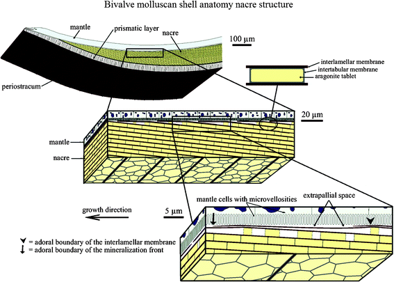 | ||
| Fig. 1 Schematic of the bivalve molluscan shell anatomy. It is composed of periostracum, a prismatic layer and nacre. The liquid-filled interlamellar space exists between the mineralized shell and the mantle part of the soft body of the organism. The schematic also illustrates successive amplifications of the brick and mortar structure of nacre. The growth surface, on which the patterns are observed, is between the mantle and the shell, and extends into the page.3 | ||
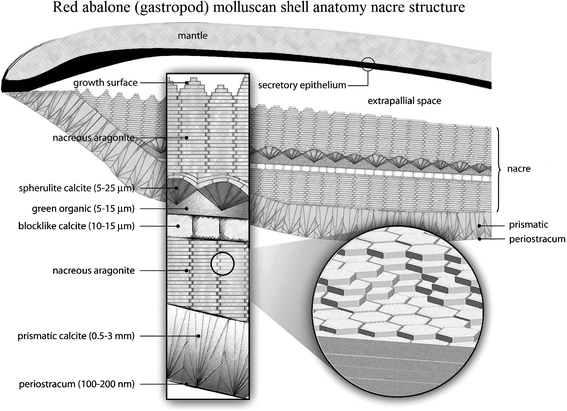 | ||
| Fig. 2 Schematic of the red abalone (gastropod) molluscan shell anatomy, showing a vertical section of the outer edge of the shell and mantle with an enlargement indicating the thickness dimensions of the shell structures. The size of the extrapallial space is exaggerated for clarity.2,112 | ||
Of the nacre-producing mollusks, bivalves and gastropods are the most common and have been studied the most.1,9 Some species of mollusk do not have nacre, such as Meretrix lusoria (bivalves) and Pecten maximus (bivalves).10Table 1 shows some mollusk shells that consist of nacre.
| Class | Family | Genus | Species | References |
|---|---|---|---|---|
| Bivalves | Meretricinae | Meretrix | Meretrix lusoria | Fleischli et al.10 |
| Mytilidae | Bathymodiolus | Bathymodiolus azoricus | Machado et al.114 | |
| Perna | Perna canaliculus (green mussel) | Leung and Sinha;106 Pokroy et al.;115 Moshe-Drezner et al.110 | ||
| Modiolus | Modiolus modiolus | Currey45 | ||
| Nuculidae | Nucula | Nucula nitidosa | Cartwright and Checa;9 Checa et al.37,94 | |
| Pinnidae (pen shell) | Atrina | Atrina pectinata | Cartwright and Checa9 | |
| Atrina rigida | Nudelman et al.88 | |||
| Atrina vexillum | Currey45 | |||
| Pteriidae | Pteria | Pteria avicula | Cartwright and Checa;9 Cartwright et al.3Fig. 1 | |
| Pteria hirundo | Cartwright and Checa;9 Cartwright et al.3 | |||
| Pteria penguin | Fleischli et al.10 | |||
| Pinctada (pearl oysters) | Pinctada maxima | Stempflé and Brendlé;107 Stempflé et al.;116 Wang et al.5 | ||
| Pinctada margaritifera | Chateigner et al.;83 Checa et al.;94 Currey;45 Currey et al.;117 Jackson et al.;13 Rousseau et al.101 | |||
| Pinctada sp. | Currey45 | |||
| Tellinidae | Tellinella | Tellinella asperrima | Ren et al.118 | |
| Unionidae | Anodonta | Anodonta cygnea (swan mussel) | Cartwright and Checa;9 Currey;45 Machado et al.114 | |
| Hyriopsis | Hyriopsis schlegeli | Song et al.119 | ||
| Lamprotula | Lamprotula fibrosa | Sun and Tong17 | ||
| Gastropods | Calliostomatidae | Calliostoma | C. zizyphinum | Cartwright and Checa9 |
| Haliotidae | Haliotis (abalone) | Haliotis asinina | Cartwright and Checa9 | |
| Haliotis fulgens (green abalone) | Lin and Meyers;91 Meyers et al.25,86 | |||
| Haliotis genus | Heinemann et al.43 | |||
| Haliotis iris | Song et al.35,36 | |||
| Haliotis laevigata (greenlip abalone) | Blank et al.;84 Heinemann et al.43 | |||
| Haliotis rufescens (red abalone) | Barthelat et al.;31,48 Bezares et al.;109,120 Fleischli et al.;10 Fritz et al.;87 Li et al.;38,54 Lin et al.68Fig. 3, Fig. 8; Lin and Meyers;91,121 Katti et al.;41,50 Menig et al.;46 Meyers et al.;32,26,86 Mohanty et al.;51 Schäffer et al.;33 Verma et al.;95 Wang et al.;5Yao et al.;102 Yourdkhani et al.;8 Zaremba et al.2 | |||
| unkonwn | Meyers and Chawla97 | |||
| Pleurotomariidae | Perotrochus | Perotrochus caledonicus | Checa et al.94 | |
| Strombidae | Strombus | Strombus gigas | Menig et al.122 | |
| Trochidae | Gibbula | Gibbula pennanti | Cartwright and Checa9 | |
| Gibbula umbilicalis | Cartwright and Checa9 | |||
| Trochus | Trochus niloticus (top shell) | Bruet et al.;49 Currey45 | ||
| Turbinidae | Bolma | Bolma rugosa | Cartwright and Checa9 | |
| Turbo | Turbo marmoratus | Chateigner et al.;83 Currey45 | ||
| Cephalopods | Nautilidae | Nautilus | Nautilus pompilius | Currey45 |
| Monoplacophora | Neopilinidae | Veleropilina | Veleropilina zografi | Checa et al.94 |
Nacre is composed of 95 wt% aragonite (a crystallographic form of CaCO3) and 5 wt% organic materials (proteins and polysaccharides). Although the organic matrix in nacre is only 5 wt%, it plays an important role in spatial and chemical control of the crystal nucleation and growth, microstructure and toughness enhancement.11,12 For example, fracture toughness of nacre is 3.3–9 MPa  , which is about three to nine times that of monolithic aragonite (about 1 MPa
  ).13–17 Nacre has been investigated for several decades due to its exceptional mechanical properties, ability to self-assemble and complex hierarchical structure, which spans the nanometer to millimeter length scales.6,8,9,12,18–30
Nacre consists of a brick-and-mortar like structure, in which hard aragonite tablets are glued together with soft organic materials to form tiles.25,31,32 Lamellar micro-architectures of hard composite tiles with soft organic layers in between can be thought of as ‘ceramic plywood’, which causes crack deflection and resists slip in order to provide toughness and impact resistance. The architecture of nacre spans from molecular, mineral bridges,33–37 to nanoscale, polygonal nanograins,38,39 nanoasperities,40 and interlocked bricks,41 over the atomic to the tens of microns length scale, with strengthening and toughening mechanisms associated with each length scale. In the literature, many studies on nacre can be found that have been conducted to investigate the reasons behind its enhanced properties.22,42
It should be pointed out that different shell-forming mollusks consist of different inner structures with varying mechanical properties.43 In general, investigations of the mechanical properties of biological materials can be divided into two major groups: (1) microscale and nanoscale indentation (mechanical properties such as elastic modulus, hardness, and toughness are determined via indentation methods); and (2) miniaturized bulk mechanical testing (compression, bending or tensile experiments for elastic modulus, strength and toughness).44 Most research in nacre consists of investigation of its micro-mechanical properties.5,13,25,44–48 Recently, with an interest in nanotechnology, the mechanical properties of nacre on the nanoscale have been investigated.17,49–53 Nanoindentation on even individual tablets has been performed.49,54
As an excellent source of inspiration, nacre has opened a way to inspire new ideas for fabricating novel materials and structures, such as biomimetic coatings,55 free standing films18,56–61 and composite materials.1,59,62–73
In this paper, we present a review of the characteristics of the hierarchical structure and mechanical properties of nacre which provide the desired properties, and the latest developments and biomimetic applications.
2 Hierarchical structure
Nacre has a complex hierarchical architecture that spans multiple length scales from the nanoscale to the macroscale,6,8,12,22,25,26 as shown in Fig. 3.26 It is an important characteristic of structural materials similarly found in bone, teeth and other tissues.27 There are some noticeable differences when examining varying species of nacre, for example the thickness of the tiles in the abalone nacre is approximately 0.5 μm, while it is around 0.3 μm for bivalve nacre.32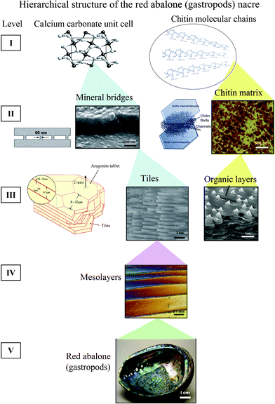 | ||
| Fig. 3 Hierarchical structure (5 levels) of the red abalone (gastropod) nacre from nano, to micro, to meso, to structural length scales.26 | ||
Several models have been proposed to explain why nacre achieves its strength owing to the microstructure of “mineral tablets embedded in a thin organic matrix”.5,40,47,74–80
In the following, we present the nacre structure, from the mesoscale to the nanoscale: two different columnar and sheet nacre structures in gastropods and bivalves, respectively; mineral bridges which represent the continuation of mineral growth along the c-axis from a preceding layer of tiles; different crystal formation and growth in gastropods and bivalves; aragonite tablets consisting of 3–10 nm polygonal nanograins; and inter-tile toughening mechanisms including plastic microbuckling, crack deflection, interlocking, nano-asperities and representative models.
2.1 Columnar and sheet structure
The precise geometric arrangement of the tiles is one of the important reasons for the robust mechanical behavior of nacre.45 There are two different mineralization types of nacre: Gibbula umbilicalis (gastropods) and Nucula nitidosa (bivalves) on the microscale, as shown in Fig. 4a.5 Nacres are “columnar nacre” or “sheet nacre”, depending on the stacking mode of the tablets (Fig. 4b). Columnar nacre has tablets of a rather uniform size with coinciding centers that determine the nucleation site of the overlying tablet, while in sheet nacre deposition takes place over most of the inner surface of the shell, and the tablets are stacked in a “brick wall” pattern, spanning the interface between the underlying tablets.81–83 Generally, columnar nacre is found in gastropods, whereas sheet nacre occurs more in bivalves.45 In columnar nacre, viewed from the top, the polygonal tablets from neighboring layers overlap in such a manner that the inter-tablet boundaries form tessellated bands perpendicular to the lamellae boundaries, shown in Fig. 4c–e.48 While in sheet nacre, the inter-tablet boundaries are distributed randomly. The overlap region in columnar nacre covers around 1/3 of the area of a tablet, whereas in sheet nacre no distinction can be made between the core and overlap areas.8,48 In columnar nacre, the distinction between the core and the overlap region is important, because the stresses experienced by these two regions are different.31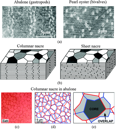 | ||
| Fig. 4 SEM images of deformation bands by tensile testing of (a) abalone (gastropods), showing four vertical dilatation bands and pearl oyster (bivalves), where the separations are randomly dispersed, and (b) schematic illustrations of columnar nacre/abalone and sheet nacre/pearl oyster. Polygonal aragonite tablets are adhered into a lamellar structure by a thin organic interlayer. In columnar nacre, the intertablet boundaries are correlated into a tessellated arrangement;5 (c) optical image of the cleaved surface shows a Voronoi like tiling of the tablets within one layer in red abalone nacre viewed from the top; (d) reconstitution of the arrangement of the tablets from one layer to the next, and (e) core and overlap areas in the tablet arrangements.48 | ||
The tablets in nacre are often described and modeled as being flat on the microscale; it was actually observed that the interfaces between the tablets show significant waviness, contributing to energy dissipation.48
2.2 Mineral bridges
The existence of mineral bridges connecting individual tablets was first demonstrated by Schäffer et al.33 and later confirmed by others. They proposed that the mineral bridges improve the mechanical properties of the organic matrix layers and prevent crack extension in nacre.9,31,35–37,68These bridges represent the continuation of mineral growth along the c-axis from a preceding layer of tiles. They protrude through the growth-arresting layers of proteins, creating sites on the covering organic layer where mineralization can continue, as shown in Fig. 5.68 To directly observe the mineral bridges between individual tablets, nacre was fractured in tension parallel to the direction of growth.35,36 In Fig. 5a, arrows mark the locations of the remaining mineral bridges, while a gap between tile layers can be clearly seen to exist in the absence of the organic matrix. Fig. 5b provides further evidence of mineral bridge formation and the aragonite surrounding individual mineral bridges seems to have semicircular bands emanating from the bridge. It has been suggested that this corresponds to a higher degree of protein absorption during the process of mineral bridge formation.79
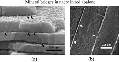 | ||
| Fig. 5 TEM images of the red abalone nacre cross-section showing (a) mineral bridges between tile interfaces and (b) mineral bridges between tablets of neighboring layers shown by arrows.79 These mineral bridges are also found in bivalves. | ||
2.3 Crystal formation and growth
The growth surface of the nacre plays a critical role in determining its mechanical properties and is a powerful crack deflector.32 During the growth of the shells, the prismatic layer is deposited first and the nacre is added as the shell thickness increases with time.29 The aragonite tablets appear as ‘stacks of coins’, where the next layer of tablets is already nucleated without the underlying layers being confluent, then tablets grow in the horizontal direction until the layer is closed.84 On the formation mechanism of individual tablets, there are three important hypotheses, being (1) single crystal growth, (2) a coherent aggregation of nanograins, and (3) phase transformation from amorphous calcium carbonate (ACC) or metastable vaterite to stable aragonite.85Fig. 6 shows the mechanism of growth of nacreous tiles by the formation of mineral bridges in gastropods; the organic layer is permeable to calcium and carbonate ions, which nourish lateral growth, as periodic secretion and deposition of the organic inter-tile membranes restricts their flux to the lateral growth surfaces.86 Arrows A designate the organic interlayer imaged by scanning electron microscopy (SEM) and arrow B designates the lateral boundary of the tile.
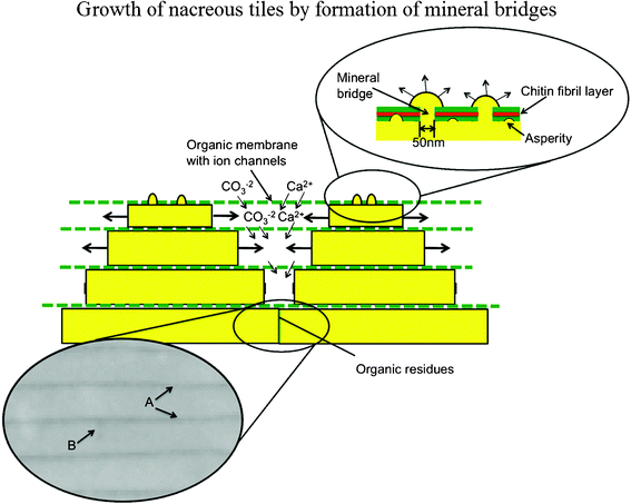 | ||
| Fig. 6 Mechanism of growth of nacreous tiles in abalone by formation of mineral bridges; the organic layer is permeable to calcium and carbonate ions, which nourish lateral growth as periodic secretion and deposition of the organic intertile membranes restricts their flux to the lateral growth surfaces. Arrows A designate the organic interlayer imaged by SEM; arrow B designates the lateral boundary of the tile.86 | ||
It has been confirmed that the growth of the aragonite component of the composite occurs by the successive nucleation of aragonite crystals and their arrest by means of a protein-mediated mechanism; it takes place in the “Christmas-tree pattern”.87 For bivalves, it usually has a rectangular, hexagonal or rounded shape when growing, but when it meets adjacent tablets and stops growing the crystal shape becomes polygonal.88Fig. 7 shows the two types of nacre structure with different formation methods. There are significant differences in the arrangement of the CaCO3 crystals, the axes along which these crystals are arranged (the crystal textures), and the way in which they are deposited.9,87,89–93 When the growth surface of nacre is viewed on the mesoscale, piles of tablets are seen to give rise to a landscape of columns in gastropods, while steps or terraces of tablets form arrangements of spirals, labyrinths and target patterns in bivalves.9,94
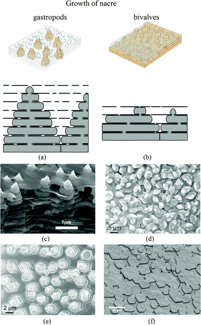 | ||
| Fig. 7 Schematic showing the growth of nacre in (a) gastropods and (b) bivalves.94,114 In the normal bivalve situation, small and scarce pores lead to 3 stacked nacre plates (in this example); in the gastropod model, pores are much more frequent and bigger in size, which allows plates to create other plates in the interlamellar space above. This results in up to 7 stacked plates. (c) SEM images of the “Christmas tree” pattern observed on the growth surface of steady state tiled aragonite gastropod red abalone nacre;25 (d) and (e) SEM image of marginal nacre in the bivalve Nucula sulcata, where tablets grow in low towers, and towered nacre in the gastropod Osilinus lineatus, respectively;37 (f) SEM image of the forming layers of bivalves Atrina rigida.88 | ||
2.4 Polygonal nanograins
On the nanoscale, the polygonal nanograins were observed on the aragonite tablets, which are the basic building blocks in nacre.54 High-resolution transmission electron microscopy (TEM) (top view) of a tablet shows nanograins of about 3–10 nm in size, shown in Fig. 8a,31 providing a ductile nature to such microstructures.33 Such deformability of the aragonite tablets is relevant for nacre's high fracture toughness.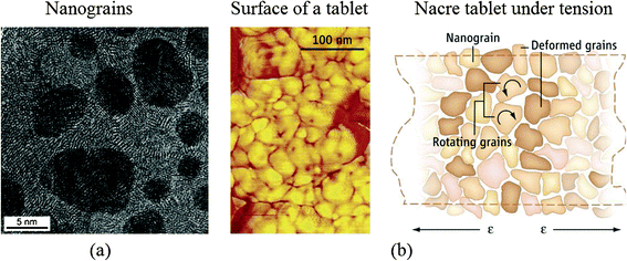 | ||
| Fig. 8 (a) High-resolution TEM (face-on view) of a tablet from the nacreous layer of a red abalone specimen showing nanograins of about 3–10 nm in size;31 (b) (left) AFM image of surface nanograins on an individual nacre platelet from California red abalone and (right) schematic of nanograin rotation under tension.38,39 | ||
Based on in situ atomic force microscopy (AFM), observations of the nanogranular texture of the aragonite tablets during mechanical deformation, nanograin rotation and deformation occur, facilitated by the existence of the biopolymer spacing between the nanograins, which will contribute to energy dissipation in nacre, shown in Fig. 8b.38,39 The water present at the nanograin interfaces may facilitate the viscoelastic features in nacre.95
2.5 Inter-tile toughening mechanism
One of the outstanding features of nacre is its high toughness. Therefore, the toughening mechanisms and their guide to materials synthesis are of interest.96 Currey45 mentioned several toughening mechanisms: plastic deformation ahead of the crack tip, crack deflection, crack blunting, and tablet pullout. Earlier research on nacre's toughening mechanisms focused mostly on crack deflection,13,97 fiber (aragonite platelet) pull out,96 and organic matrix bridging;98 recent observations on the inter-tile toughening mechanism focused dilatation band formation5,48 and nanograin rotation.38 However, it is reported that the many orders of magnitude increase in toughness cannot only be caused by tortuosity, which is one of the toughening mechanisms proposed by Sarikaya.99 (see also Meyers et al.32). Additional toughening mechanisms, such as sliding of CaCO3 layers and organic ligament formation, were thought to operate and were analyzed by Lin and Meyers.91Fig. 9 shows a plastic microbuckling event observed along the mesolayers, which is a mechanism for decreasing the overall strain energy, and was observed in a significant fraction of the specimens.46 The coordinated sliding of layer segments of the same approximate length by shear strain produces an overall rotation of the specimen in the region with a decrease in length.25 The angle α in Fig. 9 was measured and found to be approximately 35°. The ideal angle, which facilitates microbuckling, is about 45°, which means nacre exhibits a low value of kinking failure stress. The angle θ (rotation inside the kink band) is approximately 25°, determined by the interlamellar sliding.46 The rotation θ in kinking is limited by the maximum shear strain; if θ were to exceed a certain value, fracture along the sliding interfaces would occur.
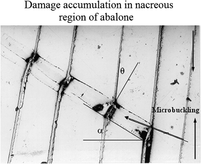 | ||
| Fig. 9 Mechanisms of damage accumulation in the nacreous region of abalone through plastic microbuckling.46 | ||
A significant mechanism of toughening is crack deflection on both the meso- and microscale, shown in Fig. 10a.97Fig. 10b shows cracks that are deflected at each soft layer. The effect of the viscoelastic glue (organic material) is to provide a crack-deflection layer, so that cracks have difficulty propagating through the composite of layers of calcium carbonate.32 The toughness of this laminated composite is vastly superior to that of a monolithic material, in which the crack would be able to propagate freely, without barriers.97 The two levels of the structure presented in Fig. 10 can be seen engaging in this mechanism: (a) mesolayers provide crack deflection, (b) on a smaller scale the tile layers force cracks into a tortuous path.79
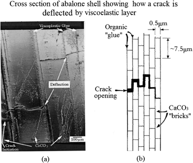 | ||
| Fig. 10 (a) Cross-section of abalone shell showing how a crack, starting at the left, is deflected by the viscoplastic layer between calcium carbonate lamellae; (b) schematic drawing showing the arrangement of calcium carbonate in nacre, forming a miniature “brick and mortar” structure.97 | ||
The interlocking of the tablets, first reported by Katti et al.,41 is shown in Fig. 11a. It appears that when two tablets are stacked above one another, rotated by a small angle relative to each other, the upper tablet with organic material is wrapped around and penetrates into the lower tablet to form the interlocks (Fig. 11b). When load is applied parallel to the tablets, the 20 nm-thick organic layer surrounding the tablet provides the deformable medium, producing additional deformation before failure of the aragonite interlock (Fig. 11c). The interlocks provide a large contribution to the strength of nacre.
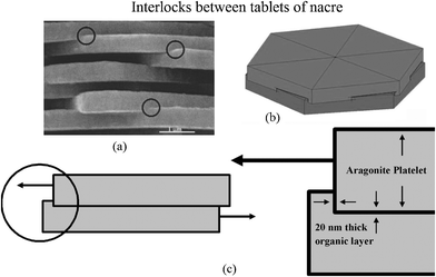 | ||
| Fig. 11 (a) SEM image of nacre from red abalone showing the presence of interlocks, indicated by circles; (b) schematic illustration showing interlocks between platelets of nacre, showing that rotation of layers of platelets is essential for the formation of platelet interlocks. (c) Schematic illustration showing the mechanism of loading through a cross-section cut across platelets and through the interlocks.41 | ||
Evans et al.40 and Wang et al.5 proposed a toughening mechanism: those nano-asperities on the tablets are responsible for the mechanical strength. The number of asperities seen in Fig. 12a exceeds considerably the values for the bridges calculated herein.5,68 These images affirm that the asperities on the upper aragonite tablet interpose with those on the lower tablet. Fig. 12b shows that the fibrils can stretch out to a remarkable length, equivalent to a strain of 150%, without becoming detached from the calcium carbonate.13Fig. 12c (i)–(iv) present schematics of the various inter-tile toughening theories.79 It is hypothesized that the asperities are the principal source of shear resistance, shown in Fig. 12c (i). Hence, plate fractures will not happen internally. Plate fractures also cause deformation delocalization. The proteins consisting of beta-pleated sheets folded into cross-linked polymer-like glue would adhere to the tiles and provide toughness through the many sacrificial bonds between proteins.98 The model for it, represented in Fig. 12c (ii), shows the viscoelastic glue model according to which the tensile strength is the result of the stretching of molecular chains whose ends are attached to the surfaces of adjacent tiles.79 At the onset of plastic deformation, broken mineral bridges may play a role in forming the asperities that subsequently resist shear,25,35,36,100 as in the model shown in Fig. 12c (iii). It is suggested here that the true mechanism of toughening is the combination of the above three models in a synergetic and harmonious collaboration, shown in Fig. 12c (iv).79 Lin and Meyers91 suggested that there are two principal mechanisms of failure when tension is applied parallel to the tile direction: tensile fracture of the tile and sliding along the tile surfaces (including breaking of the nanoscale bridges, friction produced by asperities and stretching of organic bonds). And it was deduced that the layered structure of the abalone shell provides anisotropy of mechanical strength, which increases the toughness in a significant manner by increasing the resistance to crack propagation perpendicular to the surface and decreasing it correspondingly parallel to it.26
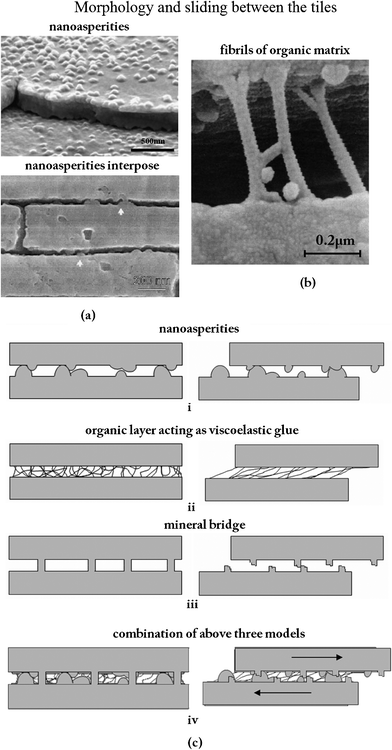 | ||
| Fig. 12 (a) Asperities (a fraction of which are remnants of mineral bridges);68 cross section of abalone nacre showing the detailed structure at the lamellae boundaries, where arrows highlight locations where the nanoasperities interpose;5 (b) fibrils of the organic matrix bridging a delamination crack. Note the large extension and ‘splayed-out’ anchorage points.13 (c) Different models for sliding between tiles:79 (i) inter-tile layer formed by asperities; (ii) organic layer acting as viscoelastic glue; (iii) mineral bridges; (iv) combination of the three mechanisms. | ||
In addition, some other microstructural features were found in nacre: the Voronoi arrangement of tablets in each tile,101 screw dislocations with unique tessellated zigzag morphology102 and interconnected layer-to-layer spiral structures39 may all play a role in the biomechanical functionality.
3 Mechanical properties
Currey45 was the first to perform measurements of the mechanical properties of nacre from a variety of bivalves, gastropods and cephalopods. He suggested that the tablet geometry and arrangement is optimized for the mechanical properties and energy absorption. This was followed by Jackson et al.13 who studied nacre from the shell of a bivalve mollusk, Pinctada, and found that the water absorbed in the organic matrix of nacre plays a significant role in its mechanical response. Following the improvement in precision and diversification of measurement techniques, more in-depth understanding about the mechanical properties of nacre has been acquired. Experimental results reveal that the mechanical properties of nacre, especially high fracture toughness, exist because of its structure.103In the following, we present the mechanical properties of nacre, which include the microscale to the nanoscale: tensile, compressive, shear, micro-scratch and tribological behaviors, nanoindentation properties and modulus mapping.
3.1 Micro-mechanical properties
Fig. 13 summarizes the compressive and ultimate tensile strengths of nacre with respect to various loading directions.32 The compressive strengths are larger than the tensile strengths in both the perpendicular and parallel directions. Mechanical properties of various nacres are shown in Table 2.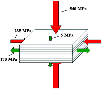 | ||
| Fig. 13 Compressive and ultimate tensile strengths of nacre under different loading directions.32 | ||
| Material | Elastic modulus (GPa) | Hardness (GPa) | Tensile strength (MPa) | Fracture toughness (MPa
|
Compressive strength (MPa) | Shear strength (MPa) | References |
|---|---|---|---|---|---|---|---|
| Testing methods:a three-point bending testing;b tensile testing;c quasi-static compression;d dynamic compression;e shear testing;f nanoindentation testing;g Vickers hardness testing;h scratch testing. Materials status: D- Dry, W- Wet, F- fresh. Loading direction: PA- parallel to the surface plane; PE- perpendicular to the tablet lamella | |||||||
| Pinctada (Pearl oysters) | 70 (D, PA),a 60 (W, PA),a 73 (D, PE),a 64 (W, PE),a | 170 (D, PA),b 140 (W, PA)b | 3.7–5 (D, PA),a 5 (W, PA),a 3.3–4.6 (D, PE),a 3.7–4.5 (W, PE)a | Jackson et al.13 | |||
| 81(D,PA),a 77(D, PE)a | Wang et al.5 | ||||||
| Pinctada maxima | 54.4–62.5 (D, PE)f | Stempflé et al.116 | |||||
| Pinctada sp. | 56 (D, PA)b | Currey45 | |||||
| Pinctada margaritifera | 87–106 (D, PA)b | Currey45 | |||||
| Hyria ligatus | 79 (D, PA)b | Currey45 | |||||
| Anodonta cygnea | 35 (D, PA)b | Currey45 | |||||
| Modiolus modiolus | 56 (D, PA)b | Currey45 | |||||
| Atrina vexillum | 86 (D, PA)b | Currey45 | |||||
| Trochus niloticus | 85 (D, PA)b | Currey45 | |||||
| 114–143 (W, PE),f 101–126(F, PE)f | 3.6–8.7 (W, PE),f 9.7–11.4 (F, PE)f | Bruet et al.49 | |||||
| 70–100 (F, PE)f | 5.41, 4.89 (F, PE)f | Villarreal123 | |||||
| Turbo marmoratus | 116 (D, PA)b | Currey45 | |||||
| Lamprotula fibrosa | 59.6 (D, PE)f | 3.42 (D, PE)f | 6.8 (D, PE)f | Sun and Tong17 | |||
| Perna canaliculus (green mussel) | 60.9 (D, PE),f 61.8–64.7 (W, PE)f | 4.5 (D, PE),f 4.1 (W, PE),f 2.55 (D, PE),g 2.7–2.75(W, PE),g 1.5–2.5 (PE)h | Leung and Sinha106 | ||||
| 147 (D, PE)f | Moshe-Drezner et al.110 | ||||||
| Nautilus pompilius | 78 (D, PA)b | Currey45 | |||||
| Haliotis rufescens (red abalone) | 7 (D, PE)a | Sarikaya et al.;14 Yasrebi et al.15 | |||||
| 9(D, PE)a | Gunnison et al.16 | ||||||
| 5 (PE)b | 235 (PA),c 540 (PE),c548 (PA),d 735 (PE)d | 30 (PA)e | Menig et al.46 | ||||
| 3 (PE)b | 250 (PE)c | Lin79 | |||||
| 90 (D, PA),b 70 (W, PA),b 14 (D, PA),e 10 (W, PA)e | Barthelat et al.48 | ||||||
| 79 (D, PE)f | 7.5(D, PE)f | Barthelat et al.31 | |||||
| 66 (D, PA),a 69 (D, PE)a | Wang et al.5 | ||||||
| 65 (F, PA)b | 36.9 (F, PA)e | Lin and Meyers121 | |||||
| 60–80 (D, PE)f | 2–4 (D, PE)f | Li et al.54 | |||||
| 14.85–113.74 (PE),f 40.95–56.71 (PE)f | 0.69–19.32 (PE),f 1.32–3.21 (PE)f | Katti et al.50 | |||||
| 10 (F, PE)b | 300–500 (F, PE)c | Meyers et al.25 | |||||
| 70–114 (D, PE)f | Bezares et al.109 | ||||||

Fig. 14a and b show the tensile and shear behavior of nacre under both dry (ambient conditions) and hydrated conditions (soaked in water), showing some ductility on the macroscale.48,104 The tensile stress–strain curves are shown in Fig. 14a; the behavior of dry nacre is similar to that of pure aragonite and failed in a brittle fashion. It showed that dehydrated nacre loses its strength. On the other hand, it demonstrated that the organic materials (5 wt%) are essential to nacre. After an initial linear response, similar to dry nacre, hydrated nacre showed a region of larger inelastic strain, starting at a stress of 70 MPa. While this mechanism can easily be envisioned as simple shear (Fig. 14b), it is less obvious in tension (Fig. 14a), because tablet sliding only occurs in the tablet overlap areas. Jackson et al.13 concluded that water affects the elastic modulus and tensile strength by reducing the shear modulus and shear strength of the organic matrix, and the toughness is enhanced by water, which plasticizes the organic matrix, resulting in greater crack blunting and deflection abilities.
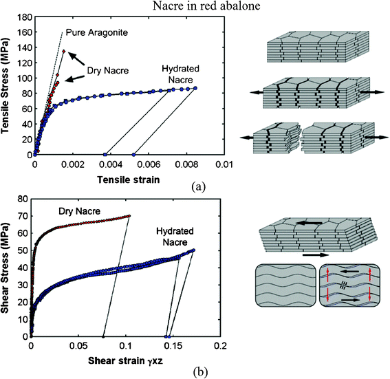 | ||
| Fig. 14 (a) Tensile and (b) shear stress–strain curves for nacre in red abalone and a schematic of lamellar tile structures showing associated deformation modes. Tablet waviness generates resistance to sliding, accompanied by lateral expansion (vertical arrows).48,104 | ||
Fig. 15 shows the compression stress–strain curves for abalone nacre, representing interlamellar shear, measured both in monotonic loading and with loading–unloading loops.5 The insert indicates that the lamella boundaries are orientated at 45° to the loading axis; the unloading–reloading measurements reveal hysteresis, indicative of internal friction and viscoelasticity.
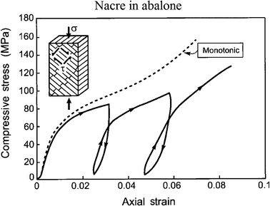 | ||
| Fig. 15 Compression stress–strain curves for nacre in abalone, representing interlamellar shear, measured both in monotonic loading and with loading–unloading loops. The insert indicates that the lamellae boundaries are orientated at 45° to the loading axis.5 | ||
Because Weibull distribution is generally a better choice for the description of strength data for ceramics, Menig et al.46 measured the compressive strength of red abalone, and found a considerable variation in results based on it. Fig. 16a and b show Weibull analysis of abalone nacre in quasi-static and dynamic compressive loading, with loading parallel and perpendicular to the layered structure.46m is the Weibull shape parameter or Weibull modulus, which is an inverse measure of the distribution width; that is, a high value of m corresponds to a narrow distribution.105 With failure probabilities of 50%, the abalone nacre is stronger with layers perpendicular to the loading direction. The dynamic strength of abalone is approximately 50% higher than its quasi-static strength. Comparing to compressive strength, m was acquired by tension perpendicular to the direction of the layers,25 and its value (1.6) is similar to that in the compressive test (2.47); in contrast the strength is dramatically smaller (5 MPa) than that in the compressive test (540 MPa).
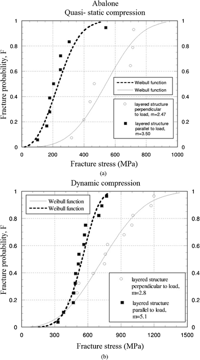 | ||
| Fig. 16 Weibull plots of abalone nacre in abalone under (a) quasi-static, and (b) dynamic compressive loading.46 | ||
For investigating the role of water content in the organic matrix and the scratch/nanoindentation hardness on the toughness mechanisms, micro-scratch tests and indentation tests were performed on the soaked and dry surfaces of nacre of green mussel shells.106 Both sets of experiments showed a decrease in hardness as a result of hydration. The data suggest that nacre toughness is affected by hydration.
Friction and wear behavior of sheet nacre has been studied in dry and wet environments.107,108 It was found that the coefficient of friction is rather high under dry conditions (0.45), and even higher under wet conditions (0.78).107 The environment influences the wear mechanisms of nacre by means of various physicochemical interactions on the water-soluble “intracrystalline” organic phase. Friction-induced damage mechanisms involving thermal effects remain largely not understood.108
3.2 Nanomechanical properties
The mechanical properties of nacre have been studied using nanoindentation experiments.49–51 Mohanty et al.51 reported the dynamic nanomechanical behavior of nacre and showed that the aragonite platelets are viscoelastic in nature and can absorb energy.The value of E for polished red abalone nacre samples was found to be between 60 and 80 GPa.54 It was also reported that there is plastic deformation in the indented region. For Trochus Niloticus nacre, the reported values of E were between 114 and 143 GPa for freshly cleaved samples and between 101 and 126 GPa for artificial seawater soaked samples.49 Images of the indents revealed extensive plastic deformation with a clear residual indent and surrounding pile-up. Compared with these values, the E value of a single tablet was 79 GPa,31 which is close to that of monolithic aragonite (81 GPa). The organic phase between the layers of aragonite tablets has been shown to exhibit E values between 2.84 and 15 GPa.31,74 This suggests that the softer interfaces and structure of the tablets have an effect on the overall mechanical properties of nacre.
Typical indent profiles of nacre from red abalone are shown in Fig. 17.109Fig. 17a and b show indentation data for dry and hydrated (or wet) nacre, respectively. Fig. 17b shows that the form of the indentation was different in that the pile-ups are far more “blunted”, with a much reduced hardness as compared to dry nacre. Scans of the indentation profiles made on heat treated nacre shown in Fig. 17c do not resemble both the dry and the wet cases. The tiles appeared to have sharp edges and displayed no pile-ups per se, and with the concomitant loss in intra-tile protein, nacre behaves as a loosely bound granular material. The indentation profiles on monolithic aragonite displayed anisotropic pile-ups, unlike nacre (Fig. 17d).
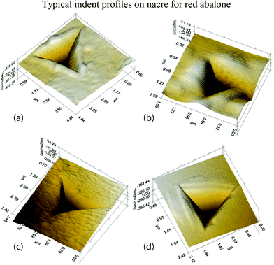 | ||
| Fig. 17 Typical indent profiles on nacre from red abalone: (a) dry nacre, there are pile-ups around the edges; (b) wet nacre, the blunted appearance of the indentation is related to the compliance of the wet nacre seen from its relatively low modulus; (c) heat treated nacre, the material appears compacted and similar to what happens to sand when it is heated and grains begin to fuse together; and (d) monolithic aragonite, the uneven pile-up indicates anisotropy.109 | ||
A modulus mapping of nacre of Perna canaliculus (green mussel), is presented in Fig. 18a.110 It shows periodic contrast produced by lighter aragonite regions separated by curved darker lines with significantly lower E. The change in E across organic–inorganic interfaces is shown in Fig. 18b, within a spatial range four times wider than the thickness of the organic layers.
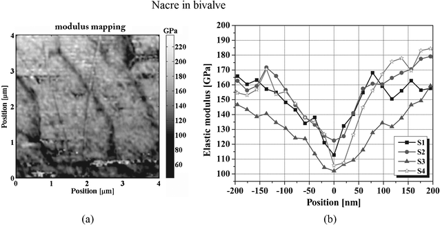 | ||
| Fig. 18 (a) Map of elastic modulus taken from the nacre layer at a depth of 300 μm beneath the inner surface of the bivalve shells of Perna canaliculus; (b) the modulus change across organic–inorganic interfaces.110 | ||
Using force mode AFM, it has been shown that a very large force is required (>5–6 nN) to pull the proteins away from the aragonite, which suggests that the molecular interactions at the organic–inorganic interface in nacre are substantial and may play a significant role in the overall toughness of nacre.111
4 Bioinspired structures
Mimicking the nacre hierarchical structure is more complex than other biomimetic structures. Hierarchically-structured materials typically offer control over two degrees of hierarchy: (i) thickness and orientation of the layers and (ii) control of the interfacial properties between layers (roughness, residual stresses).112 Overall, the mimicking of nacre is mainly focused on (1) structure, including laminated structure, hierarchical structure, brick-like structure, or organic and inorganic multilayered structure (brick-and-mortar structure), (2) manufacturing process, that means mimicking its mineralization process, and (3) components, mimicking its 5 wt% organic with inorganic materials for producing artificial nacre. These design concepts and fabrication methods have been used with various nonmetallic materials and polymers for enhancing or improving their original mechanical properties.A laminated structure of Al-B4C was produced by Sarikaya and Aksay.113 They reported that it was five times tougher than monolithic B4C. Thenceforth the highly organized microarchitecture and extraordinary mechanical response of nacre have inspired scientists to develop synthetic nanocomposite materials mimicking nacre.12Table 3 shows some refined ceramic materials that were bioinspired by the structure of nacre. The fracture toughness of biomimetic composite materials approached that of nacre. The bioinspired structures of nacre have also been applied to composite materials,1,59,62–73 coatings,55 and films.18,56–61 Nacre-mimetic paper has been fabricated with lightweight, shape-persistent, excellent and tunable mechanical properties, and heat and fire-shielding capabilities.61
| Bioinspired nacre structural materials | Scale | Fracture toughness (MPa
|
Reference |
|---|---|---|---|
| a Polymethyl methacrylate (PMMA) | |||
| Al/Al–Si | μm | 5.5–10 | Deville et al.59 |
| Al2O3/Al–Si | μm | 40 | Lin et al.;123 Launey et al.72 |
| Al2O3/PMMAa | μm | 30 | Munch et al.69 |
| Al2O3/TiO2 | mm | 12 | Bueno and Baudín70 |
| SiC/Al2O3–Y2O3 | mm | 14 | Zhang and Krstic63 |
| Si3N4/BN | mm | 28 | Wang et al.64 |

Based on fabrication methods, the bioinspired structures can be considered from two different points of view: hierarchical structure (top-down) and self-assembled nanocomposite (bottom-up).112 Due to the wide range of applications of the biomimetic nacre structure, various fabrication methods have been used. On the nanoscale, as an example, a high-strength and highly transparent nacre-like nanocomposite has been prepared via a layer-by-layer assembly technique from poly (vinyl alcohol) (PVA) and Na+-montmorillonite clay nanosheets, which are strong, flexible, but also highly transparent.60 The preparation of a “nacre-like” nanocomposite (NC) via layer-by-layer (LBL) assembly of the poly (diallyldimethylammonium chloride) polycation (PDDA) is shown in Fig. 19a. The growth profile of the films, characterized with UV-vis spectroscopy and ellipsometry (Fig. 19b), revealed fairly linear growth. The resulting films were found to be strong, flexible, but also highly transparent, which was attributed to the nanoscale dimensions of the inorganic phase (Fig. 19c and 19d) and high orientation of inorganic clay nanosheets of Na+-montmorillonite (MTM). AFM phase imaging revealed full platelet coverage of the surface resembling that of nacre (Fig. 19e). SEM imaging revealed a high degree of MTM ordering into a well defined lamellar structure (Fig. 19f).
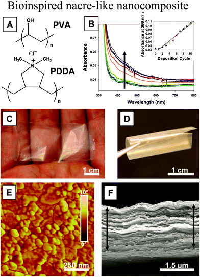 | ||
| Fig. 19 (a) Structure of PVA and PDDA polymers; (b) UV-vis spectra for the first 10 bilayers of deposition (arrow indicates increasing absorbance, inset represents absorbance at 360 nm as a function of the bilayer); (c, d) optical images of a free-standing film of (PVA–MTM)300 showing very high transparency and flexibility; (e) AFM phase image of a single PVA–MTM bilayer; (f) SEM image of the cross section of a 300-bilayer PVA–MTM composite showing its laminar architecture. The films in SEM can be slightly expanded due to separation of the layers resulting from the shearing force of the razor blade used for cutting the test samples.60 | ||
Upon increasing to the millimeter scale, the design concept of the bioinspired structure of nacre is also suitable for fabrication. Based on the structure of natural nacre, as an example, PMMA tablets exhibiting unique mechanisms were generated.1 Progressive tablet locking, strain hardening, and spreading of large deformations over large volumes were all achieved in this material. The proposed nacre-like composite material is shown in Fig. 20a. Its main features are borrowed directly from the following design features of natural nacre: stiff and brittle tablets arranged in a columnar fashion with well-defined overlap and core regions, interfaces between the tablets to maintain cohesion over long sliding distances, and waviness on the tablets to generate strain hardening and spread deformations and reinforcements in the core regions. The anticipated behavior in tension of such a composite is shown in Fig. 20b. The dovetails are critical in generating progressive locking, and the stresses involved in this mechanism are shown in Fig. 20c. The resulting material, shown in Fig. 20d, consisted of seven layers and was composed of eight columns of tablets.
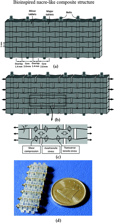 | ||
| Fig. 20 Overview of the nacre-like composites: (a) schematic with dimensions; (b) tablets under tension slide with progressive locking; (c) some of the stresses involved in progressive locking; (d) actual composite after assembly.1 | ||
Wang et al.103 summarized various fabrication methods, which have been used in six categories: the conventional method for bulk ceramic materials, freezing casting, layer-by-layer deposition, electrophoretic deposition, mechanical assembly, and chemical self-assembly. Almost all fabrication methods are based on laminate processing.28 However, the biomimetic structures of nacre have not considered the subtle structures found in nacre, such as tablet waviness, mineral bridges and nanoasperities. With the progress of fabrication methods and theory, the artificial nacre materials will have similar or better mechanical properties in future and can be used in many fields.
Summary
A review of the structure–property relationships in nacre covering the length span from mesoscale features to the nanoscale is presented. Nacre is composed of 95% aragonite (CaCO3) and 5% organic materials. Nacre consists of columnar architectures and sheet tiles, mineral bridges, polygonal nanograins and nanoasperities, showing that nacre is a hierarchical structure material. Aragonite is sandwiched with organic materials and consists of a lamellar bricks-and-mortar microarchitecture with high fracture toughness and strength.Even though many species of mollusk have a nacreous layer, bivalves and gastropods are the most common and have been the most studied. Data have been presented to understand the mechanisms responsible for good mechanical properties, which include crack deflection, fiber and tablet pull out, organic matrix bridging, dilatation band formation, asperities which resist shear, and nanograin rotation. The mechanical properties of nacre result from its structure and, specifically, from its highly organized micro-architecture with its precise arrangement of mineral platelets. Dry nacre behaves like a monolithic ceramic and fails in a brittle fashion; the elastic modulus of hydrated nacre is lower than that of dry nacre. The water present at the nanograin interfaces also contributes to the viscoelastic nature of nacre.
This research has intrigued materials scientists for decades and has been the subject of biomimetic design. Some examples presented show recent attempts to mimic the structure and properties of nacre using engineered systems.
Acknowledgements
This work was supported by National Natural Science Foundation of China (grant no. 31172144), by the Science & Technology Development Projects of Jilin Province (grant no. 20090147), by the Basic Operation Foundation of Jilin University (grant no. 200903271), Project of the National Twelfth-Five Year Research Program of China (2011BAD20B09-15), and by “Project 985” of Jilin University. We would like to thank Prof. Shunjin Peng for discussion in the materials field.References
- F. Barthelat and D. J. Zhu, “A novel biomimetic material duplicating the structure and mechanics of natural nacre”, J. Mater. Res., 2011, 26, 1203–1215 CrossRef CAS.
- C. M. Zaremba, A. M. Belcher, M. Fritz, Y. Li, S. Mann, P. K. Hansma, D. E. Morse, J. S. Speck and G. D. Stucky, “Critical transitions in the biofabrication of abalone shells and flat pearls”, Chem. Mater., 1996, 8, 679–690 CrossRef CAS.
- J. H. E. Cartwright, A. G. Checa, B. Escribano and C. I. Sainz-Díaz, “Spiral and target patterns in bivalve nacre manifest a natural excitable medium from layer growth of a biological liquid crystal”, Proc. Natl. Acad. Sci. U. S. A., 2009, 106, 10499–10504 CrossRef CAS.
- M. Lopes-lima, A. Rocha, F. Goncxalves, J. Andrade and J. Machado, “Microstructural characterization of inner shell layers in the freshwater bivalve Anodonta Cygnea”, J. Shellfish Res., 2010, 29, 969–973 CrossRef.
- R. Z. Wang, Z. Suo, A. G. Evans, N. Yao and I. A. Aksay, “Deformation mechanisms in nacre”, J. Mater. Res., 2001, 16, 2485–2493 CrossRef CAS.
- F. Barthelat, “Biomimetics for next generation materials”, Philos. Trans. R. Soc. London, Ser. A, 2007, 365, 2907–2919 CrossRef CAS.
- D. K. Dubey and V. Tomar, “Role of molecular level interfacial forces in hard biomaterial mechanics: a review”, Ann. Biomed. Eng., 2010, 38, 2040–2055 CrossRef.
- M. Yourdkhani, D. Pasini and F. Barthelat, “Multiscale mechanics and optimization of gastropod shells”, J. Bionic Eng., 2011, 8, 357–368 CrossRef.
- J. H. E. Cartwright and A. G. Checa, “The dynamics of nacre self-assembly”, J. R. Soc. Interface, 2007, 4, 491–504 CrossRef CAS.
- F. D. Fleischli, M. Dietiker, C. Borgia and R. Spolenak, “The influence of internal length scales on mechanical properties in natural nanocomposites: A comparative study on inner layers of seashells”, Acta Biomater., 2008, 4, 1694–1706 CrossRef CAS.
- D. Verma, K. Katti and D. Katti, “Photoacoustic FTIR spectroscopic study of undisturbed nacre from red abalone”, Spectrochim. Acta, Part A, 2006, 64, 1051–1057 CrossRef.
- K. S. Katti, D. R. Katti, B. Mohanty, “Biomimetic Lessons Learnt from Nacre”, in Biomimetics Learning from Nature, ed. Amitava Mukherjee, InTech, India, 2010 Search PubMed.
- A. P. Jackson, J. F. V. Vincent and R. M. Turner, “The mechanical design of nacre”, Proc. R. Soc. London, Ser. B, 1988, 234, 415–440 CrossRef.
- M. Sarikaya, K. E. Gunnison, M. Yasrebi and I. A. Aksay, “Mechanical property-microstructural relationships in abalone shell”, MRS Proc., 1989, 174, 109 CrossRef.
- M. Yasrebi, G. H. Kim, K. E. Gunnison, D. L. Milius, M. Sarikaya and I. A. Aksay, “Biomimetic processing of ceramics and ceramic-metal composites”, MRS Proc., 1990, 180, 625–636 CrossRef CAS.
- K. E. Gunnison, M. Sarikaya, J. Liu and I. A. Aksay, “Structure-mechanical property relationships in a biological ceramic-polymer composite”, MRS Proc., 1991, 255, 171–184 CrossRef.
- J. Y. Sun and J. Tong, “Fracture toughness properties of three different biomaterials measured by nanoindentation”, J. Bionic Eng., 2007, 4, 11–17 CrossRef.
- Z. Y. Tang, N. A. Kotov, S. Magonov and B. Ozturk, “Nanostructured artificial nacre”, Nat. Mater., 2003, 2, 413–418 CrossRef CAS.
- B. D. Ratner and S. J. Bryant, “Biomaterials: where we have been and where we are going”, Annu. Rev. Biomed. Eng., 2004, 6, 41–75 CrossRef CAS.
- P. Podsiadlo, S. Paternel, J. M. Rouillard, Z. F. Zhang, J. Lee, J. W. Lee, L. Gulari and N. A. Kotov, “Layer-by-layer assembly of nacre-like nanostructured composites with antimicrobial properties”, Langmuir, 2005, 21, 11915–11921 CrossRef CAS.
- P. Podsiadlo, A. K. Kaushik, E. M. Arruda, A. M. Waas, B. S. Shim, J. D. Xu, H. Nandivada, B. G. Pumplin, J. Lahann, A. Ramamoorthy and N. A. Kotov, “Ultrastrong and stiff layered polymer nanocomposites”, Science, 2007, 318, 80–83 CrossRef CAS.
- F. Barthelat, “Nacre from mollusk shells: a model for high-performance structural materials”, Bioinspir. Biomim., 2010, 5, 035001–1-8 CrossRef.
- L. J. Bonderer, A. R. Studart and L. J. Gauckler, “Bioinspired design and assembly of platelet reinforced polymer films”, Science, 2008, 319, 1069–1073 CrossRef CAS.
- R. F. Chen, C. A. Wang, Y. Huang and H. R. Le, “An efficient biomimetic process for fabrication of artificial nacre with ordered-nano structure”, Mater. Sci. Eng., C, 2008, 28, 218–222 CrossRef CAS.
- M. A. Meyers, A. Y. M. Lin, P. Y. Chen and J. Muyco, “Mechanical strength of abalone nacre: role of the soft organic layer”, J. Mech. Behav. Biomed. Mater., 2008, 1, 76–85 CrossRef.
- M. A. Meyers, P. Y. Chen, M. I. Lopez, Y. Seki and A.Y.M. Lin, “Biological materials: A materials science approach”, J. Mech. Behav. Biomed. Mater., 2011, 4, 626–657 CrossRef.
- B. Bhushan, “Biomimetics: lessons from nature—an overview”, Philos. Trans. R. Soc. London, Ser. A, 2009, 367, 1445–1486 CrossRef CAS.
- G. M. Luz and J. F. Mano, “Biomimetic design of materials and biomaterials inspired by the structure of nacre”, Philos. Trans. R. Soc. London, Ser. A, 2009, 367, 1587–1605 CrossRef CAS.
- G. M. Luz and J. F. Mano, “Mineralized structures in nature: Examples and inspirations for the design of new composite materials and biomaterials”, Compos. Sci. Technol., 2010, 70, 1777–1788 CrossRef CAS.
- K. S. Liu and L. Jiang, ”Bio-inspired design of multiscale structures for function integration”, Nano Today, 2011, 6, 155–175 CrossRef CAS.
- F. Barthelat, C.M. Li, C. Comi and H. D. Espinosa, “Mechanical properties of nacre constituents and their impact on mechanical performance”, J. Mater. Res., 2006, 21, 1977–1986 CrossRef CAS.
- M. A. Meyers, P. Y. Chen, A.Y.M. Lin and Y. Seki, “Biological materials: Structure and mechanical properties”, Prog. Mater. Sci., 2008, 53, 1–206 CrossRef CAS.
- T. E. Schäffer, C. IonescuZanetti, R. Proksch, M. Fritz, D. A. Walters, N. Almqvist, C. M. Zaremba, A. M. Belcher, B. L. Smith, G. D. Stucky, D. E. Morse and P. K. Hansma, “Does abalone nacre form by heteroepitaxial nucleation or by growth through mineral bridges?”, Chem. Mater., 1997, 9, 1731–1740 CrossRef.
- F. Song and Y. L. Bai, “Mineral bridges of nacre and its effects”, Acta Mech. Sin., 2001, 17, 251–257 CrossRef.
- F. Song, X. H. Zhang and Y. L. Bai, “Microstructure and characteristics in the organic matrix layers of nacre”, J. Mater. Res., 2002, 17, 1567–1570 CrossRef CAS.
- F. Song, A. K. Soh and Y. L. Bai, “Structural and mechanical properties of the organic matrix layers of nacre”, Biomaterials, 2003, 24, 3623–3631 CrossRef CAS.
- A. G. Checa, J. H. E. Cartwright and M. G. Willinger, “Mineral bridges in nacre”, J. Struct. Biol., 2011, 176, 330–339 CrossRef CAS.
- X. D. Li, Z. H. Xu and R. Z. Wang, “In situ observation of nanograin rotation and deformation in nacre”, Nano Lett., 2006, 6, 2301–2304 CrossRef CAS.
- C. Ortiz and M. C. Boyce, “Bioinspired structural materials”, Science, 2008, 319, 1053–1054 CrossRef CAS.
- A. G. Evans, Z. Suo, R. Z. Wang, I. A. Aksay, M. Y. He and J. W. Hutchinson, “Model for the robust mechanical behavior of nacre”, J. Mater. Res., 2001, 16, 2475–2484 CrossRef CAS.
- K. S. Katti, D. R. Katti, S. M. Pradhan and A. Bhosle, “Platelet interlocks are the key to toughness and strength in nacre”, J. Mater. Res., 2005, 20, 1097–1100 CrossRef CAS.
- R. Z. Wang and H. S. Gupta, “Deformation and fracture mechanisms of bone and nacre”, Annu. Rev. Mater. Res., 2011, 41, 41–73 CrossRef CAS.
- F. Heinemann, M. Launspach, K. Gries and M. Fritz, “Gastropod nacre: structure, properties and growth—biological, chemical and physical basics”, Biophys. Chem., 2011, 153, 126–153 CrossRef CAS.
- S. Bechtle, S.F. Ang and G. A. Schneider, “On the mechanical properties of hierarchically structured biological materials”, Biomaterials, 2010, 31, 6378–6385 CrossRef CAS.
- J. D. Currey, “Mechanical properties of mother of pearl in tension”, Proc. R. Soc. London, Ser. B, 1977, 196, 443–463 CrossRef.
- R. Menig, M. H. Meyers, M. A. Meyers and K. S. Vecchio, “Quasi-static and dynamic mechanical response of Haliotis rufescens (abalone) shells”, Acta Mater., 2000, 48, 2383–2398 CrossRef CAS.
- F. Barthelat and H. D. Espinosa, “An experimental investigation of deformation and fracture of nacre–mother of pearl”, Exp. Mech., 2007, 47, 311–324 CrossRef.
- F. Barthelat, H. Tang, P. D. Zavattieri, C. M. Li and H. D. Espinosa, “On the mechanics of mother-of-pearl: A key feature in the material hierarchical structure”, J. Mech. Phys. Solids, 2007, 55, 306–337 CrossRef CAS.
- B. J. F. Bruet, H. J. Qi, M. C. Boyce, R. Panas, K. Tai, L. Frick and C. Ortiz, “Nanoscale morphology and indentation of individual nacre tablets from the gastropod mollusc Trochus niloticus”, J. Mater. Res., 2005, 20, 2400–2419 CrossRef CAS.
- K. S. Katti, B. Mohanty and D. R. Katti, “Nanomechanical properties of nacre”, J. Mater. Res., 2006, 21, 1237–1242 CrossRef CAS.
- B. Mohanty, K. S. Katti, D. R. Katti and D. Verma, “Dynamic nanomechanical response of nacre”, J. Mater. Res., 2006, 21, 2045–2051 CrossRef CAS.
- B. Bhushan, Springer Handbook of Nanotechnology, Springer-Verlag, Heidelberg, Germany, 3rd edn, 2010 Search PubMed.
- B. Bhushan, Biomimetics: Bioinspired Hierarchical-Structured Surfaces for Green Science and Technology, Springer-Verlag, Heidelberg, Germany, 2012 Search PubMed.
- X. D. Li, W. C. Chang, Y. J. Chao, R. Wang and M. Chang, “Nanoscale structural and mechanical characterization of a natural nanocomposite material: the shell of red abalone”, Nano Lett., 2004, 4, 613–617 CrossRef CAS.
- A. Sellinger, P. M. Weiss, A. Nguyen, Y. F. Lu, R. A. Assink, W. L. Gong and C. J. Brinker, “Continuous self-assembly of organic–inorganic nanocomposite coatings that mimic nacre ”, Nature, 1998, 394, 256–260 CrossRef CAS.
- M. Rubner, “Synthetic sea shell”, Nature, 2003, 423, 925–926 CrossRef CAS.
- S. M. Zhang, J. W. Zhang, Z. J. Zhang, H. X. Dang, W. M. Liu and Q. J. Xue, “Preparation and characterization of self-assembled organic-inorganic nacre-like nanocomposite thin films”, Mater. Lett., 2004, 58, 2266–2269 CrossRef CAS.
- X. Zhang, C. L. Liu, W. J. Wu and J. F. Wang, “Evaporation-induced self-assembly of organic–inorganic ordered nanocomposite thin films that mimic nacre”, Mater. Lett., 2006, 60, 2086–2089 CrossRef CAS.
- S. Deville, E. Saiz, R. K. Nalla and A. P. Tomsia, “Freezing as a path to build complex composites”, Science, 2006, 27, 515–518 CrossRef.
- P. Podsiadlo, A. K. Kaushik, B. S. Shim, A. Agarwal, Z. Tang, A. M. Waas, E. M. Arruda and N. A. Kotov, “Can nature's design be improved upon? High strength, transparent nacre-like nanocomposites with double network of sacrificial cross links”, J. Phys. Chem. B, 2008, 112, 14359–14363 CrossRef CAS.
- A. Walther, I. Bjurhager, J.-M. Malho, J. Ruokolainen, L. Berglund and O. Ikkala, “Supramolecular control of stiffness and strength in lightweight high-performance nacre-mimetic paper with fire-shielding properties”, Angew. Chem., Int. Ed., 2010, 49, 6448–6453 CrossRef CAS.
- N. P. Padture, D. C. Pender, S. Wuttiphan and B. R. Lawn, “In situ processing of silicon carbide layer structures”, J. Am. Ceram. Soc., 1995, 78, 3160–3162 CrossRef CAS.
- L. Zhang and V. D. Krstic, “High toughness silicon carbide/graphite laminar composite by slip casting”, Theor. Appl. Fract. Mech., 1995, 24, 13–19 CrossRef CAS.
- C. A. Wang, Y. Huang, Q. F. Zan, H. Guo and S.Y. Cai, “Biomimetic structure design—a possible approach to change the brittleness of ceramics in nature”, Mater. Sci. Eng., C, 2000, 11, 9–12 CrossRef.
- G. Mayer, “Rigid biological systems as models for synthetic composites”, Science, 2005, 310, 1144–1147 CrossRef CAS.
- G. Mayer, “New classes of tough composite materials—lessons from natural rigid biological systems”, Mater. Sci. Eng., C, 2006, 26, 1261–1268 CrossRef CAS.
- H. Wei, N. Ma, F. Shi, Z. Q. Wang and X. Zhang, “Artificial nacre by alternating preparation of layer-by-layer polymer films and CaCO3 strata”, Chem. Mater., 2007, 19, 1974–1978 CrossRef CAS.
- A. Y. M. Lin, P. Y. Chen and M. A. Meyers, “The growth of nacre in the abalone shell”, Acta Biomater., 2008, 4, 131–138 CrossRef.
- E. Munch, M. E. Launey, D. H. Alsem, E. Saiz, A. P. Tomsia and R. O. Ritchie, “Tough bio-inspired hybrid materials”, Science, 2008, 322, 1516–1520 CrossRef CAS.
- S. Bueno and C. Baudín, “Design and processing of a ceramic laminate with high toughness and strong interfaces”, Composites, Part A, 2009, 40, 137–143 CrossRef.
- T. H. Lin, W. H. Huang, I. K. Jun and P. Jiang, “Bioinspired assembly of colloidal nanoplatelets by electric field”, Chem. Mater., 2009, 21, 2039–2044 CrossRef CAS.
- M. E. Launey, E. Munch, D. H. Alsem, E. Saiz, A. P. Tomsia and R. O. Ritchie, “A novel biomimetic approach to the design of high-performance ceramic–metal composites”, J. R. Soc. Interface, 2010, 7, 741–753 CrossRef CAS.
- H. Kakisawa and T. Sumitomo, “The toughening mechanism of nacre and structural materials inspired by nacre”, Sci. Technol. Adv. Mater., 2011, 12, 064710–1-14 CrossRef.
- D. R. Katti and K. S. Katti, “3D finite element modeling of mechanical response in nacre-based hybrid nanocomposites”, J. Mater. Sci., 2001, 36, 1411–1417 CrossRef CAS.
- K. Okumura and P. G. de Gennes, “Why is nacre strong? Elastic theory and fracture mechanics for biocomposites with stratified structures”, Eur. Phys. J. E: Soft Matter Biol. Phys., 2001, 4, 121–127 CrossRef CAS.
- K. S. Katti, D.R. Katti, J. Tang, S. Pradhan and M. Sarikaya, “Modeling mechanical responses in a laminated biocomposite. Part II. Nonlinear responses and nuances of nanostructure”, J. Mater. Sci., 2005, 40, 1749–1755 CrossRef CAS.
- H. J. Gao, “Application of fracture mechanics concepts to hierarchical biomechanics of bone and bone-like materials”, Int. J. Fract., 2006, 138, 101–137 CrossRef.
- H. Tang, F. Barthelat and H.D. Espinosa, “An elasto-viscoplastic interface model for investigating the constitutive behavior of nacre”, J. Mech. Phys. Solids, 2007, 55, 1410–1438 CrossRef CAS.
- A. Y. M. Lin, Structural and functional biological materials: abalone nacre, sharp materials, and abalone foot adhesion. PhD thesis, University of California, San Diego, 2008 Search PubMed.
- K. Tushtev, M. Michael and G. Georg, “On the nature of the stiffness of nacre”, Mater. Sci. Eng., C, 2008, 28, 1164–1172 CrossRef CAS.
- C. Hedegaard, “Shell structures of the recent Vetigastropoda”, J. Molluscan Stud., 1997, 63, 369–377 CrossRef.
- C. Hedegaard and H. Wenk, “Microstructure and texture patterns of mollusc shells”, J. Molluscan Stud., 1998, 64, 133–136 CrossRef.
- D. Chateigner, C. Hedegaard and H. Wenk, “Mollusc shell microstructures and crystallographic textures”, J. Struct. Geol., 2000, 22, 1723–1735 CrossRef.
- S. Blank, M. Arnoldi, S. Khoshnavaz, L. Treccani, M. Kuntz, K. Mann, G. Grathwohl and M. Fritz, “The nacre protein perlucin nucleates growth of calcium carbonate crystals”, J. Microsc., 2003, 212, 280–291 CrossRef CAS.
- L. Qiao, Q.L. Feng and S.S. Lu, “In vitro growth of nacre-like tablet forming: From amorphous calcium carbonate, nanostacks to hexagonal tablets”, Cryst. Growth Des., 2008, 8, 1509–1514 CAS.
- M. A. Meyers, C. T. Lim, A. B. R. Li, H. Nizam, E. P. S. Tan, Y. Seki and J. McKittrick, “The role of organic intertile layer in abalone nacre”, Mater. Sci. Eng. C, 2009, 29, 2398–2410 CrossRef CAS.
- M. Fritz, A. M. Belcher, M. Radmacher, D. A. Walters, P. K. Hansma, G. D. Strucky and D. E. Morse, “Flat pearls from biofabrication of organized composites on inorganic substrates”, Nature, 1994, 371, 49–51 CrossRef CAS.
- F. Nudelman, B. A. Gotliv, L. Addadi and S. Weiner, “Mollusk shell formation: Mapping the distribution of organic matrix components underlying a single aragonitic tablet in nacre”, J. Struct. Biol., 2006, 153, 176–187 CrossRef CAS.
- H. Nakahara, “Nacre formation in bivalve and gastropod molluscs”, in Mechanisms and Phylogeny of Mineralization in Biological Systems, ed. S. Suga and H. Nakahara, Springer-Verlag, Tokyo, 1991, pp. 343–350 Search PubMed.
- S. Weiner and L. Addadi, “Design strategies in mineralized biological materials”, J. Mater. Chem., 1997, 7, 689–702 RSC.
- A. Y. M. Lin and M. A. Meyers, “Growth and structure in abalone shell”, Mater. Sci. Eng., A, 2005, 390, 27–41 CrossRef.
- D. J. Jackson, C. McDougall, B. Woodcroft, P. Moase, R. A. Rose, M. Kube, R. Reinhardt, D. S. Rokhsar, C. Montagnani, C. Joubert, D. Piquemal and B. M. Degnan, “Parallel evolution of nacre building gene sets in molluscs”, Mol. Biol. Evol., 2010, 27, 591–608 CrossRef CAS.
- L. P. Xie, F. J. Zhu, Y. J. Zhou, C. Yang and R. Q. Zhang, “Molecular approaches to understand biomineralization of shell nacreous layer”, Prog Mol Subcell Biol, 2011, 52, 331–352 CrossRef.
- A. G. Checa, J. H. E. Cartwright and M. G. Willinger, “The key role of the surface membrane in why gastropod nacre grows in towers”, Proc. Natl. Acad. Sci. U. S. A., 2009, 106, 38–43 CrossRef CAS.
- D. Verma, K. Katti and D. Katti, “Nature of water in nacre: a 2D Fourier transform infrared spectroscopic study”, Spectrochim. Acta, Part A, 2007, 67, 784–788 CrossRef.
- R. Z. Wang, H. B. Wen, F. Z. Cui, H. B. Zhang and H. D. Li, “Observations of damage morphologies in nacre during deformation and fracture”, J. Mater. Sci., 1995, 30, 2299–2304 CrossRef CAS.
- M. A. Meyers and K.K. Chawla, Mechanical behavior of materials, Cambridge University Press, New York, 2008 Search PubMed.
- B. L. Smith, T. E. Schäffer, M. Viani, J. B. Thompson, N. A. Frederick, J. Kindt, A. Belcher, G. D. Stucky, D. E. Morse and P. K. Hansma, “Molecular mechanistic origin of the toughness of natural adhesive, fibres and composites”, Nature, 1999, 399, 761–763 CrossRef CAS.
- M. Sarikaya, “An introduction to biomimetics: a structural viewpoint”, Microsc. Res. Tech., 1994, 27, 360–375 CrossRef CAS.
- G. Mayer, “New toughening concepts for ceramic composites from rigid natural materials”, J. Mech. Behav. Biomed. Mater., 2011, 4, 670–681 CrossRef.
- M. Rousseau, E. Lopez, A. Couté, G. Mascarel, D. C. Smithc, R. Naslaind and X. Bourrat, “Sheet nacre growth mechanism: a Voronoi model”, J. Struct. Biol., 2005, 149, 149–215 CrossRef.
- N. Yao, A. Epstein and A. Akey, “Crystal growth via spiral motion in abalone shell nacre”, J. Mater. Res., 2006, 21, 1939–1946 CrossRef CAS.
- J. F. Wang, Q. F. Cheng and Z. Y. Tang, “Layered nanocomposites inspired by the structure and mechanical properties of nacre”, Chem. Soc. Rev., 2012, 41, 1111–1129 RSC.
- F. Barthelat, J. Rim, H. D. Espinosa, “A review on the structure and mechanical properties of mollusk shells—perspectives on synthetic biomimetic materials” in Applied Scanning Probe Methods XIII, ed. B. Bhushan and H. Fuchs, Springer, 2009, pp. 1059–1100. Search PubMed.
- J. B. Wachtman, Mechanical Properties of Ceramics, Wiley-Interscience, New York, 1996 Search PubMed.
- H. M. Leung and S. K. Sinha, “Scratch and indentation tests on seashells”, Tribol. Int., 2009, 42, 40–49 CrossRef CAS.
- P. Stempflé and M. Brendlé, “Tribological behaviour of nacre-Influence of the environment on the elementary wear processes”, Tribol. Int., 2006, 39, 1485–1496 CrossRef.
- P. Stempflé, T. Djilali, R. K. Njiwa, M. Rousseau, E. Lopez and X. Bourrat, “Thermal-induced wear mechanisms of sheet nacre in dry friction”, Tribol. Lett., 2009, 35, 97–104 CrossRef.
- J. Bezares, Z. L. Peng, R. J. Asaro and Q. Zhu, “Macromolecular structure and viscoelastic response of the organic framework of nacre in Haliotis rufescens: a perspective and overview”, Theort. Appl. Mech., 2011, 38, 75–106 CrossRef.
- H. Moshe-Drezner, D. Shilo, A. Dorogoy and E. Zolotoyabko, “Nanometer-scale mapping of elastic modules in biogenic composites: The nacre of mollusk shells”, Adv. Funct. Mater., 2010, 20, 2723–2728 CrossRef CAS.
- B. Mohanty, K. S. Katti and D. R. Katti, “Experimental investigation of nanomechanics of the mineral-protein interface in nacre”, Mech. Res. Commun., 2008, 35, 17–23 CrossRef.
- S. Deville, E. Saiz, A. P. Tomsia, “Using ice to mimic nacre: from structural applications to artificial bone”, in Handbook of Biomineralization: Biomimetic and Bioinspired Chemistry, ed. P. Behrens and E. Bäuerlein, John Wiley & Sons, Ltd, Weinheim, Germany, 2008 Search PubMed.
- M. Sarikaya, I. A. Aksay, “Nacre of abalone shell: a natural multifunctional nanolaminated ceramic-polymer composite malarial”, in Results and Problems in Cell Differentiation – Biopolymers, ed. S. T. Case, Springer-Verlag, Berlin, 1992 Search PubMed.
- J. Machado, M. Lopes-Lima, A. Damasceno-Oliveira, A. Colaço, J. Andrade, D. Silva, C. Jiménez-López, A. Rodríguez-Navarro and A. Checa, “The influence of hydrostatic pressure on shell mineralization of Anodonta cygnea: A comparative study with a hydrothermal vent bivalve Bathymodiolus azoricus”, J. Shellfish Res., 2009, 28, 899–904 CrossRef.
- B. Pokroy, V. Demensky and E. Zolotoyabko, “Nacre in mollusk shells as a multilayered structure with strain gradient”, Adv. Funct. Mater., 2009, 19, 1054–1059 CrossRef CAS.
- P. Stempflé, O. Pantalé, M. Rousseau, E. Lopez and X. Bourrat, “Mechanical properties of the elemental nanocomponents of nacre structure”, Mater. Sci. Eng., C, 2010, 30, 715–721 CrossRef.
- J. D. Currey, P. Zioupos, P. Davies and A. Casinos, “Mechanical properties of nacre and highly mineralized bone”, Proc. R. Soc. London, Ser. B, 2001, 268, 107–111 CrossRef CAS.
- F. Z. Ren, X. D. Wan, Z. H. Ma and J. H. Su, “Study on microstructure and thermodynamics of nacre in mussel shell”, Mater. Chem. Phys., 2009, 114, 367–370 CrossRef CAS.
- F. Song, J. B. Zhou, X. H. Xu, Y. Xu and Y. L. Bai, “Effect of a negative poisson ratio in the tension of ceramics”, Phys. Rev. Lett., 2008, 100, 245502–1-4 CrossRef.
- J. Bezares, R. J. Asaro and M. Hawley, “Macromolecular structure of the organic framework of nacre in Haliotis rufescens: Implications for growth and mechanical behavior”, J. Struct. Biol., 2008, 163, 61–75 CrossRef CAS.
- A. Y. M. Lin and M. A. Meyers, “Interfacial shear strength in abalone nacre”, J. Mech. Behav. Biomed. Mater., 2009, 2, 607–612 CrossRef.
- R. Menig, M. H. Meyers, M.A. Meyers and K. S. Vecchio, “Quasi-static and dynamic mechanical response of Strombus gigas (conch) shells”, Mater. Sci. Eng., 2001, A297, 203–211 CAS.
- J. E. Villarreal, Mapping of elastic modulus and hardness in Trochus niloticus seashell nacre, Masters thesis, Massachusetts Institute of Technology, Cambridge, Massachusetts, 2007 Search PubMed.
| This journal is © The Royal Society of Chemistry 2012 |