High density and high aspect ratio solid micro-nanoprojection arrays for targeted skin vaccine delivery and specific antibody extraction
Derek
Jenkins†
ab,
Simon
Corrie†
a,
Christopher
Flaim
a and
Mark
Kendall
ac
aThe University of Queensland, Australian Institute for Bioengineering and Nanotechnology, St Lucia, QLD 4072, Australia. E-mail: m.kendall@uq.edu.au; Fax: +61 7 3346 3973; Tel: +61 7 3346 4209
bISIS Facility, STFC Rutherford Appleton Laboratory, Harwell Science and Innovation Campus, Didcot, United Kingdom
cThe University of Queensland, Diamantina Institute for Cancer, Immunology and Metabolic Medicine, Princess Alexandra Hospital, Ipswich Rd, Woolloongabba, QLD 4102, Australia
First published on 1st March 2012
Abstract
We introduce and describe a methodology for fabricating high-density and high aspect ratio micro-nanoprojection arrays—and further demonstrate the utility of these devices in targeting the skin for two different healthcare applications. The key to achieving the unprecedented high projection density (>20![[thin space (1/6-em)]](https://www.rsc.org/images/entities/char_2009.gif) 000 cm−2) is the use of a controlled mixed plasma in a DRIE process, producing long, tapered tips without limiting the overall feature density. With a tailored process we produce structures of tuneable shape and height, with high uniformity across the face of silicon wafers. We show that these devices are suitable for both biological delivery and biomarker-specific extraction applications.
000 cm−2) is the use of a controlled mixed plasma in a DRIE process, producing long, tapered tips without limiting the overall feature density. With a tailored process we produce structures of tuneable shape and height, with high uniformity across the face of silicon wafers. We show that these devices are suitable for both biological delivery and biomarker-specific extraction applications.
Introduction
Micro-nanoprojection arrays (MNPs) are emerging as innovative tools for next-generation healthcare applications.1–3 As one example, targeted delivery of high molecular weight compounds (e.g. vaccines) to the immunologically rich areas of the skin's epidermis and dermis has been a key application driving the field.4–10 Furthermore, arrays of micropillars have been incorporated into microfluidic devices in order to provide high surface area capture surfaces for biomarkers of diagnostic interest.11 More recently we also demonstrated—for the first time—the extraction and detection of antigen-specific antibodies from the intact dermis of live mice.12 These broad advances show the great potential of MNPs as an enabling technology in both the drug delivery and diagnostics fields. For both applications, a high surface area of the projections in contact with the target skin layer is crucial. Therefore we have designed the MNPs with both a high density and aspect ratio. Whilst application of these devices has been reported previously,4–10,13–16 the design and fabrication process has not previously been described in any detail.Previously, others have worked with low density (1–100 cm−2) and medium density (100–5000 cm−2) arrays, fabricated using metal,17,18 polymer,19 ceramic,20 and silicon substrates.21,22 Using the MNPs developed in our group (>20000 cm−2), a specialized method was developed to apply the patches to the skin and achieve consistent, incremental and controlled penetration into targeted skin layers.16 Biological results of these devices include: potent vaccination with reduced doses (compared to standard needle and syringe injection),4–10,14 selective biomarker extraction23 and fundamental insights in to mechanisms driving skin immune cell transport.9,24
With the focus moving towards human application, there is a need to fabricate silicon-chip based MNPs to the required high-density and high aspect ratio designs. In particular, given the architecture and mechanical properties of skin, devices useful for accessing the epidermis and superficial dermis are likely to require projections ≥ 100 μm in length, with tips tapered to nanoscale sharpness (hence the term “micro-nanoprojections”). In contrast, cylindrical “micropillars” do not appear to efficiently penetrate the tough skin outer layers.25 Furthermore, a previous study found that the insertion force required to penetrate skin increased linearly with the cross-sectional area of the tip.26 Collectively, this suggests that sharp, tapered projections at high density are desirable for skin targeting applications.
With this goal in mind, established silicon etching processes do not appear to be suitable. “Wet etch” processes (based on anisotropic etching behaviour in an alkaline solution) are technically elegant and simple, but the density, tip angle and hence aspect ratio are fixed by the silicon crystal lattice structure (Fig. 1a). Extension of these tips is theoretically possible but as yet unreported.27,28 Tapered structures can also be created using isotropic “dry etching” (i.e. lateral and vertical etching rates are held equal), which produces a characteristic parabolic profile (Fig. 1b). However, the density is limited by the radius of curvature (e.g. for a MNP array height of 100 μm, the density is limited to 2500 cm−2).29 The use of oxygen as a passivation gas does allow some control of the projection taper, requiring a hard mask (e.g. chrome or silicon oxide) to be used,21 thereby adding to the cost and complexity of manufacture. Furthermore, the reactivity of the silicon surface with oxygen means that the wafer cannot be removed for quality assurance checks during the etching process. Combining an isotropic etch with a Bosch process (Fig. 1b schematic), Chabri et al. 2004 increased density to 5000 cm−2 and penetrated into the corneal layers, however the penetration depth was limited by the short, broad tips.30
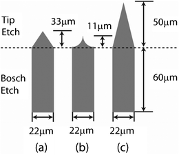 | ||
| Fig. 1 Tip geometries resulting from various tip etching methods combined with the same Bosch process. (a) wet etch; (b) isotropic DRIE; (c) controlled mixed plasma etch DRIE as developed in the current study. Due to the inherent geometric limitations for (a) and (b), the tips are significantly shorter in comparison to (c). | ||
Here, we introduce a fabrication process to produce high density MNPs (>20000 cm−2) consisting of high aspect-ratio tips extended vertically to a user-defined final height (Fig. 1c). We achieved the desired tip profile (Fig. 2a) by using a controlled mixing of SF6 and C4F8 plasma in an anisotropic etch process. The addition of a simple Bosch etch extended the projections to the desired length (Fig. 2b and c). Finally, we applied our fabricated MNPs to the skin, demonstrating proof of concept in two distinct healthcare applications. Specifically, we applied 110 μm MNPs to the ear skin of live mice. Then we separately demonstrated their utility for inducing an immune response using a model antigen (ovalbumin) and also for extracting anti-ovalbumin-IgG from immunized animals using surface-modified projections.
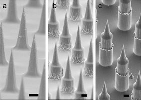 | ||
| Fig. 2 Scanning electron microscopy of MNP arrays showing (a) tapered tip profile; (b) tapered tip plus short Bosch etch; (c) tapered tip plus longer Bosch etch. Note scale bar = 10 μm. | ||
Design
Micro-nanoprojection array fabrication process
To enable high density (≥5000 projections/cm2) MNP fabrication, a controlled mixed plasma etch process was developed in which the lateral and vertical etch rates could be carefully controlled to produce the tapered tip (Fig. 1c). Importantly, this method enabled us to tune the shape of the tip to suit our desired high aspect ratios, in turn allowing us to operate at higher densities. In this work, SF6 and C4F8 are introduced simultaneously, unlike the Bosch process where these same gases are alternately introduced so that C4F8 is both deposited and removed, acting as a passivation gas for the SF6 isotropic etch. However, preferentially vertical etching occurs due to ion bombardment arising from the bias voltage. Under appropriate conditions, the vertical and lateral etch rates can be controlled, yielding tips with high aspect ratios. We then produced a tuneable projection height with a subsequent Bosch etch to produce 110 μm-long projections for mouse penetration. Indeed, we will extend the approach to further lengthening the projections to achieve epidermal/dermal penetration in thicker human skin.31To fabricate MNPs, we first deposited a SU8 photoresist onto a <100> silicon wafer as a physical mask, followed by controlled mixed plasma etching to create the tapered tip (Fig. 2a). Extension of the projections to the desired height was achieved using a standard Bosch process (Fig. 2b and c). We removed the residual SU8 mask using oxygen plasma. Finally, a 1–2 μm thick silicon oxide layer was grown in a dry oxygen furnace at 1060 °C followed by acid etching to remove the oxide, resulting in sharpened silicon projections.
Results and discussion
Process development and optimization
As a first step towards fabricating MNPs with the desired shape profile and geometry, we characterized the mixed plasma etching process. The aim is finding the effects of varying the key etching parameters on the resultant vertical and lateral etch rates (Fig. 3). Increasing the molar ratio of passivant/etchant (keeping total flowrate constant) linearly (approximately) decreased lateral and vertical etching rates (Fig. 3a) without significant effects on wafer uniformity.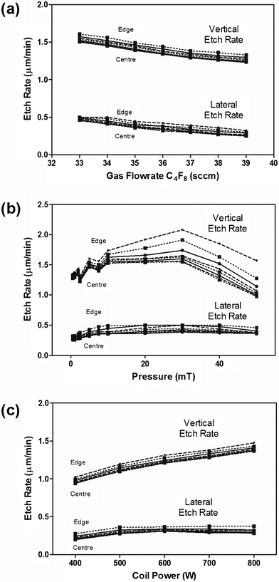 | ||
| Fig. 3 Effect of key process parameters on vertical and lateral etch rates as a function of position; specifically (a) molar flowrate of C4F8 keeping total flow constant; (b) total system pressure, and (c) input coil power. | ||
Turning to uniformity across the wafer: it appeared that reducing the total system pressure was the most influential way to achieve the tightest uniformity. Indeed, we found the lowest stable pressure yielded the most uniform lateral and vertical etch rates (Fig. 3b)—as shown by the smallest variation in vertical etch rates between the edge and the centre of the wafer at lower system pressures. In contrast, coil power did not have a significant effect on uniformity. However higher power resulted in significantly faster vertical etch rates—so we operated at 800 W (Fig. 3c). While stable operation is more challenging as the system pressure dropped, 1 mT yielded the best compromise between system stability and uniformity. Due to the highly uniform etching across the wafer independent of molar flowrates, we considered varying the passivant flowrate as the best way to fine-tune the shape and profile of the projections. For our needs, 37 sccm passivant resulted in projections with 45–55 μm height and 22 μm base diameter. Therefore, we established the operating conditions for generating the desired shape profile of our micro-nanoprojection tips,
Next, we kept these conditions constant and varied the size of the SU-8 features and the spacing between them (“pitch”). We varied the feature size (30, 40 or 50 μm circles) while also varying the pitch (70, 100, 150 μm) with the resultant lateral etch rates shown in Fig. 4. We found that as the feature size was increased, the uniformity across the wafer also increased (Fig. 4a–c)—as evidenced by the more uniform lateral etch rates. However, the lateral etch rate shows with an increased pitch the uniformity decreased. Based on these competing effects, and the increased projection density using the smallest pitch, we chose to use the 30 μm feature size and 70 μm pitch combination for the remainder of the experiments in the current study.
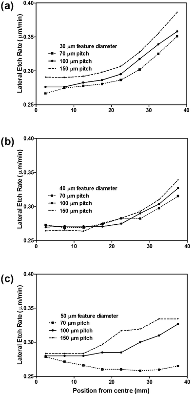 | ||
| Fig. 4 Effect of dot pitch on lateral etch rate as a function of circular mask feature size; (a) 30 μm, (b) 40 μm, or (c) 50 μm diameters. | ||
It is important for the MNPs to be fabricated repeatably: both within a single silicon wafer and between etches. So, to explore repeatability, we etched 30 wafers using the 30/70 photomask to produce the tapered tips (Fig. 5). After the tip etch, average projection height within each wafer was 50.8 ± 1.9 μm (measured by SEM) and the average between wafers was 50.8 ± 3.0 μm.
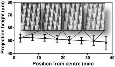 | ||
| Fig. 5 Uniformity of projection geometry as a function of position on silicon wafer using optimized process. | ||
Fig. 5 shows that while the projection height was consistent across the wafer, the outer edges of the wafer contained thinner projections with high surface roughness and pitting, due to overetching. This effect was consistent in the radial dimension from the centre of each wafer. Overall, the yield of useful MNPs was at least 55%. Following successful fabrication of micro-nanoprojection arrays, we extended the projections to 110 μm using a Bosch etch (Fig. 2c) and applied these devices in two challenging biomedical applications—vaccine delivery and biomarker extraction. Both of these experiments required MNPs to pierce the tough outer skin layers to target the epi/dermal layers—containing both immune-sensitive cells and serum rich fluid.
Model vaccine delivery to skin and resultant immune response
For delivery of sensitive vaccine reagents, we coated the arrays with a mixture of OVA (model vaccine) and Quil-A (adjuvant which boosts immune response) dissolved in a methylcellulose solution. When applied to the skin of live mice, the MNPs breached the tough outer layers of the skin and released their payload into the epidermis and dermis (Fig. 6a). Based on our measurements of 14C-OVA left on the MNP array, in the ear, or on the skin surface, we observed ∼8% delivery efficiency (Fig. 6b). After 21 days, blood sera was collected from the animals and assayed for OVA-specific IgG titres by ELISA assay (Fig. 6c, inset) showing a significantly higher antibody response in comparison to unimmunized animals or those vaccinated via intramuscular injection with the same dose. These results clearly showed that the MNP array delivered a model vaccine antigen to immune-sensitive regions of the skin resulting in a stronger immune response when compared to the gold standard intramuscular (IM) needle/syringe delivery method. These findings are consistent with reported improvements in immunogenicity achieved by applying MNPs, fabricated by the approach detailed here, across a range of diseases tested in mice.4–10 While the delivered dose efficiency in this case was relatively low, this is within the range observed previously.32 Technical advances in projection coating from our group and others have shown improvements of up to 80–90 %.6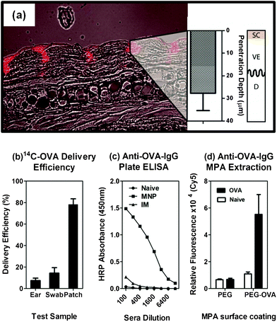 | ||
| Fig. 6 Demonstration of MNP utility for biomedical applications using mouse models. (a) Uniform penetration into the dermis was achieved as previously reported; note that SC = stratum corneum, VE = viable epidermis and D = dermis; (b) delivery of a 14C-labelled ovalbumin protein was confirmed by scintillation counting and (c) after 21 days the mice mounted a strong specific antibody response; (d) selective extraction of the Anti-ovalbumin-IgG was confirmed at the same time using a modified ELISA assay on the MNP surface. | ||
Selective extraction of model biomarker anti-OVA-IgG from skin
We next used the same MNPs to demonstrate selective biomarker extraction from the skin. The key difference here is the need for surface treatments of projections in order to both (a) extract specific biomarkers whilst (b) reducing the extraction of non-specific material. We did this by grafting a heterobifunctional polyethylene glycol (HS-PEG-COOH) to the surface at high grafting density,23 to reduce non-specific protein fouling. The thiol group at one end adsorbed to the gold surface while the carboxy group was available in solution for carbodiimide-mediated protein attachment (PEG only). After attaching the OVA protein to the arrays (PEG-OVA arrays), we applied the devices to the skin of mice previously vaccinated with OVA in order to extract anti-OVA-IgG. Fig. 6d shows that these PEG-OVA arrays captured significant amounts of anti-OVA-IgG from the skin of vaccinated mice in comparison to naïve animals or those tested using PEG arrays only. The presence of anti-OVA-IgG antibody was detected using a Cy5-labelled mouse anti-IgG and imaging was performed using a confocal microarray laser scanner. This shows that MNPs can be used, through different post-fabrication coating schemes, for at least two different applications in the biomedical arena.Conclusions
We have fabricated MNP arrays with high density (>20000 cm−2), high aspect ratio and high uniformity, suitable for both drug delivery and biomarker extraction applications. We found that by controlling the process parameters during the DRIE process, we were able to control the tip profile, produce a long conical feature capable of dermal penetration at relatively low application velocities. Using different surface modification strategies we were able to (a) deliver a model vaccine antigen into the skin to produce a specific and strong IgG response, and (b) extract the ovalbumin-specific IgG onto the projection surface for direct detection. This work represents an important step forward in the fabrication of densely packed, high aspect ratios for lab-on-chip applications.
Experimental
Microfabrication
Lithography was completed on a Karl Suss mask aligner at a power setting of 10 mA cm−2. SU-8 was selected as the resist material due to the ability to spin thick layers (> 10 μm), good critical dimension characteristics and excellent etch rate selectivity during deep silicon etching. SU8 2025 photoresist (Microchem) was spin coated onto silicon <100> wafers, baked on a hotplate according to the manufacturers instructions, and exposed through a chrome mask. After a post exposure bake, the resist was developed in polypropylene glycol monomethylethyl acetate (PGMEA). The SU8 structures remaining served as the physical mask during the etching process.Deep silicon etch processing was carried out in an inductively coupled plasma system produced by Surface Technology System (STS), containing two 15.56 MHz RF generators (coil 1.2 kW and the plate 50 W). The silicon wafer was mechanically clamped using ceramic fingers. Pressure in the system can be controlled in automatic or manual modes via a butterfly valve. Masked silicon substrates were etched using a controlled anisotropic mixed plasma recipe followed by a standard Bosch etch recipe where indicated. For all controlled anisotropic mixed plasma recipes, the etch time was approximately 30 min, and the total flow rate (C4F8 plus SF6) was held constant at 100 sccm—the contribution of each gas to this total was adjusted during the characterization phase. Residual SU8 masking structures were removed using an oxygen plasma in a RIE (Oxford instrument System 90), to prevent contamination of the thermal oxidation furnace. An approximately 1 μm thick layer of thermal oxide was grown in a dry furnace at 1060 °C for 20 h, followed by a quick dip in [7:1] hydrofluoric acid (HF). The wafers were subsequently sputter-coated with ∼100 nm of gold using a ∼20 nm chrome adhesion layer. Processed wafers were mounted on dicing film and diced to 4 mm × 4 mm using a diamond saw (MicroAce). Etch rates were estimated from mask undercut and silicon depth measurements taken from SEM images (Leica EBL40) of 30 min etches. Measurements were made in ImageJ, and the etch rate was assumed to be constant. For each condition, five measurements were made.
OVA vaccination
Vaccination using ovalbumin coated MNP's was performed as described previously.16 All animal experiments were performed in accordance with the animal ethics regulations of The University of Queensland. In brief, ovalbumin protein 10 mg mL−1 (OVA, Sigma #A5503 or 14C-OVA, American Radiochemicals) and Quil-A 2 mg mL−1 as the adjuvant was suspended in a solution containing 1% methylcellulose, and dry-coated onto the projections using jet coating.15 OVA-coated MNP's were then applied to 6–8 week old C57BL/6 mice using a spring loaded impact applicator.16 Two MNP arrays were applied to each mouse (one to each ear), whilst they were anaesthetised (n = 5/group), and maintained on the skin for five minutes each after initial application to ensure full coating dissolution. A positive control dose-matched to the MNP group was injected intramuscularly (n = 5/group), with a negative control of unvaccinated mice (n = 5/group). Mice were bled at 21 days and anti-OVA IgG titres were measured using an Enzyme Linked Immunosorbent Assay (ELISA).33 Radio scintillation counting of whole skin, MNP and skin swab samples containing 14C-OVA after application was performed using a Tricarb system (Perkin Elmer).MNP extraction analysis
For extraction purposes, MNPs were coated with a non-fouling heterobifunctional polyethylene glycol (HS-PEG-COOH, 5000 Da, Creative PEG Works, USA) layer via gold-thiol interactions at the cloud point using a process described by Corrie et al. 2010.12 Water-soluble carbodiimide coupling chemistry was then used to covalently attach the OVA protein at a concentration of 20 μg mL−1. Mice were vaccinated with 6 μg OVA protein intramuscularly and the surface modified MNPs were applied to the mouse ears under anaesthesia for 20 min on day 21 (as described above, n = 4). Following application, MNPs were placed in microwell plates filled with 100 μL PBST washing buffer (PBS, 0.05% tween-20) and washed four times. Goat anti-mouse-IgG labelled with Alexa Fluor 647 (Invitrogen, #A21237) was diluted 1:600 in PBST and added to the microwells containing each MNP. After 30 min incubation on an orbital shaker, the MNPs were washed again four times in PBST. MNPs were then mounted on a microscope slide under a coverslip and imaged using a confocal fluorescent scanner fitted with a 633 nm laser and 650 nm emission bandpass filter (LS Reloaded, Tecan, Switzerland) and the average fluorescence intensity per MNP was recorded using ImageJ.
Data analysis
For process optimization and MNP metrology purposes, etch rate data was calculated based on SEM measurement of projection height and tip diameter based on n = 5 for each position on a wafer. Error bars for each datapoint in Fig. 3 are not included on the graphs, but in all cases were < 5% CV. For the uniformity characterization, 30 wafers were characterized in this way. All biological data (Fig. 6) is presented as mean plus/minus standard deviation using the GraphPad PRISM V5.03 software.References
- M. Kendall, Vaccine, 2006, 24, 4651–4656 CrossRef CAS.
- M. R. Prausnitz and R. Langer, Nat. Biotechnol., 2008, 26, 1261–1268 CrossRef CAS.
- M. R. Prausnitz, Adv. Drug Delivery Rev., 2004, 56, 581–587 CrossRef CAS.
- H. J. Corbett, G. J. P. Fernando, X. Chen, I. H. Frazer and M. A. F. Kendall, PLoS One, 2010, 5, e13460 Search PubMed.
- X. Chen, G. J. P. Fernando, M. L. Crichton, C. Flaim, S. R. Yukiko, E. J. Fairmaid, H. J. Corbett, C. A. Primiero, A. B. Ansaldo, I. H. Frazer, L. E. Brown and M. A. F. Kendall, J. Controlled Release, 2011, 152, 349–355 CrossRef CAS.
- X. Chen, H. Corbett, S. R. Yukiko, A. P. Raphael, E. J. Fairmaid, L. E. Brown, I. H. Frazer, G. J. Fernando and M. A. Kendall, Adv. Funct. Mater., 2011, 21, 464–473 CrossRef CAS.
- X. F. Chen, A. S. Kask, M. L. Crichton, C. McNeilly, S. Yukiko, L. C. Dong, J. O. Marshak, C. Jarrahian, G. J. P. Fernando, D. X. Chen, D. M. Koelle and M. A. F. Kendall, J. Controlled Release, 2010, 148, 327–333 CrossRef CAS.
- G. J. P. Fernando, X. F. Chen, T. W. Prow, M. L. Crichton, E. J. Fairmaid, M. S. Roberts, I. H. Frazer, L. E. Brown and M. A. F. Kendall, PLoS One, 2010, 5, 11 Search PubMed.
- T. W. Prow, X. Chen, N. A. Prow, G. J. P. Fernando, C. S. E. Tan, A. P. Raphael, D. Chang, M. P. Ruutu, D. W. K. Jenkins, A. Pyke, M. L. Crichton, K. Raphaelli, L. Y. H. Goh, I. H. Frazer, M. S. Roberts, J. Gardner, A. A. Khromykh, A. Suhrbier, R. A. Hall and M. A. F. Kendall, Small, 2010, 6, 1776–1784 CrossRef CAS.
- A. P. Raphael, T. W. Prow, M. L. Crichton, X. Chen, G. J. P. Fernando and M. A. F. Kendall, Small, 2010, 6, 1785–1793 CrossRef CAS.
- Y. J. Liu, S. S. Guo, Z. L. Zhang, W. H. Huang, D. Baigl, M. Xie, Y. Chen and D. W. Pang, Electrophoresis, 2007, 28, 4713–4722 CrossRef CAS.
- S. R. Corrie, G. J. P. Fernando, M. L. Crichton, M. E. G. Brunck, C. D. Anderson and M. A. F. Kendall, Lab on a Chip, 2010, 10, 2655–2658 RSC.
- M. L. Crichton, B. C. Donose, X. Chen, A. P. Raphael, H. Huang and M. Kendall, Biomaterials, 2011, 32, 4670–4681 CrossRef CAS.
- A. S. Kask, X. F. Chen, J. O. Marshak, L. C. Dong, M. Saracino, D. Chen, C. Jarrahian, M. A. Kendall and D. M. Koelle, Vaccine, 2010, 28, 7483–7491 CrossRef CAS.
- X. Chen, T. W. Prow, M. L. Crichton, D. W. K. Jenkins, M. S. Roberts, I. H. Frazer, G. J. P. Fernando and M. A. F. Kendall, Journal of Controlled Release, 2009, 139 CAS.
- M. L. Crichton, A. Ansaldo, X. Chen, T. W. Prow, G. J. P. Fernando and M. A. F. Kendall, Biomaterials, 2010, 31, 4562–4572 CrossRef CAS.
- W. Martanto, S. P. Davis, N. R. Holiday, J. Wang, H. S. Gill and M. R. Prausnitz, Pharm. Res., 2004, 21, 947–952 CrossRef CAS.
- H. S. Gill and M. R. Prausnitz, J. Controlled Release, 2007, 117, 227–237 CrossRef CAS.
- J. H. Park, M. G. Allen and M. R. Prausnitz, J. Controlled Release, 2005, 104, 51–66 CrossRef CAS.
- A. Doraiswamy, C. Jin, R. J. Narayan, P. Mageswaran, P. Mente, R. Modi, R. Auyeung, D. B. Chrisey, A. Ovsianikov and B. Chichkov, Acta Biomater., 2006, 2, 267–275 CrossRef CAS.
- S. Henry, D. V. McAllister, M. G. Allen and M. R. Prausnitz, J. Pharm. Sci., 1998, 87, 922–925 CrossRef CAS.
- P. Van Damme, F. Oosterhuis-Kafeja, M. Van der Wielen, Y. Almagor, O. Sharon and Y. Levin, Vaccine, 2009, 27, 454–459 CrossRef.
- S. R. Corrie, G. J. P. Fernando, M. L. Crichton, M. E. G. Brunck, C. D. Anderson and M. A. F. Kendall, Lab on a Chip, 2010, 10 Search PubMed.
- M. P. Ruutu, X. Chen, O. Joshi, M. A. Kendall and I. H. Frazer, Exp. Dermatol., 2011, 20, 534–536 CrossRef CAS.
- A. L. Teo, C. Shearwood, K. C. Ng, J. Lu and S. Moochhala, Mater. Sci. Eng., B, 2006, 132, 151–154 CrossRef CAS.
- S. P. Davis, B. J. Landis, Z. H. Adams, M. G. Allen and M. R. Prausnitz, J. Biomech., 2004, 37, 1155–1163 CrossRef.
- N. Wilke and A. Morrissey, J. Micromech. Microeng., 2007, 17, 238–244 CrossRef CAS.
- N. Wilke, A. Mulcahy, S. R. Ye and A. Morrissey, Microelectron. J., 2005, 36, 650–656 CrossRef CAS.
- J. Jing, F. E. Tay, J. Miao and C. Iliescu, J. Phys. Conf. Ser., 2006, 34, 1127–1131 CrossRef.
- N. Roxhed, P. Griss and G. Stemme, J. Micromech. Microeng., 2007, 17, 1087–1092 CrossRef.
- M. Huzaira, F. Rius, M. Rajadhyaksha, R. R. Anderson and S. Gonzalez, J. Invest. Dermatol., 2001, 116, 846–852 CrossRef CAS.
- X. Chen, T. W. Prow, M. L. Crichton, D. W. Jenkins, M. S. Roberts, I. H. Frazer, G. J. Fernando and M. A. Kendall, J. Controlled Release, 2009, 139, 212–220 CrossRef CAS.
- G. J. Fernando, l. D. J. Stenze, R. W. Tindle, M. S. Merza, B. Morein and I. H. Frazer, Vaccine, 1995, 13, 1460–1467 CrossRef CAS.
Footnote |
| † These authors contributed equally and share lead authorship. |
| This journal is © The Royal Society of Chemistry 2012 |