Environmental assessment of electrically controlled variable light transmittance devices
Uwe
Posset
*a,
Matthias
Harsch
b,
Aline
Rougier
c,
Bettina
Herbig
a,
Gerhard
Schottner
a and
Gerhard
Sextl
d
aFraunhofer-Institut für Silicatforschung ISC, Neunerplatz 2, D-97082, Würzburg, Germany. E-mail: uwe.posset@isc.fraunhofer.de; Fax: +49-(0)931-4100-698; Tel: +49-(0)931-4100-660
bLCS Life Cycle Simulation GmbH, Aspacher Strasse 9, D-71522, Backnang, Germany
cCNRS, Université de Bordeaux, ICMCB, 87 avenue du Dr A. Schweitzer, Pessac F-33608, France
dChemische Technologie der Materialsynthese, Julius-Maximilians-Universität Würzburg, Röntgenring 11, D-97070, Würzburg
First published on 18th April 2012
Abstract
A comprehensive benchmark analysis has been performed on five electrically controlled state-of-the-art transmittance modulation devices including their production routes, from ‘cradle-to-gate’. The benchmarks have been modeled employing the GaBi life cycle assessment software tool, which successfully yielded the most important environmental problem areas for the product life cycles of electrochromic and electrotropic light-modulating devices. In terms of the energy demand of processing, all-solid-state technology was found to be less favorable than wet-chemical electrodeposition processes; however, the effect is interestingly overcompensated for by the resource depletion resulting from higher layer thicknesses in the latter case. As opposed to the mineral-glass based benchmarks, a plastic-film based system was particularly favorable, implying that the substrate is a factor with a strong environmental impact in transmittance modulation devices. Eventually, very high impacts were found for tin-doped indium oxide (ITO) and iridium oxide, i.e. a common transparent conductor and anodic electrochromic material, respectively. The results obtained support important current trends such as in-line manufacturing of electrochromic devices, the quest for ITO replacement materials, and, in general, the replacement of energy- and resource-intensive processes (sputter deposition of heavy metal oxides) by less demanding methods.
Introduction
Nowadays, due both to the general public's growing awareness of the environment and to more restrictive environmental legislation, product and production decisions are based not only on economic and technological criteria but also on environmental aspects. It is important in many industries to know and understand the environmental impacts associated with their products and processes, and how to manage these negative effects in the best way possible, in ecological and economic terms. The Life Cycle Assessment (LCA) methodology allows production decisions to be taken from the point of view of environmental aspects, from raw material through production, use, and recycling or disposal.For this purpose, it is necessary to perform a compilation and evaluation of the inputs and outputs as well as potential environmental impacts associated with these, in each step of the production process and throughout the life cycle of the product. All the material and energy flows, as well as the relevant environmental releases involved in the complete life cycle of the product, are defined, characterized, and quantified.
An LCA study comprises the following four major steps:
• The definition of goal and scope, depending on subject and intended use of the study.
• The Life Cycle Inventory (LCI), meaning the compilation of an inventory of any inputs and outputs of each step of the process.
• The Life Cycle Impact Assessment (LCIA), where the potential environmental impacts associated with the inputs and outputs are evaluated.
• The analysis and interpretation of the results.
The goal of the present study is the ecological LCA of prototypes for the electrically controlled modulation of visible light transmittance, i.e., electrochromic (EC) or electrotropic (ET) smart windows, and their production routes “from the cradle”. The term ‘electrochromic’ refers to systems with the ability to change their optical absorption characteristics (and hence their color) upon application of an electrical voltage, while ‘electrotropic’ refers to variable light scattering properties. Usually, an EC system changes its color from an almost colorless transparent to a dark tinted transparent state, while an ET system changes from a translucent to a transparent state, usually without a change in color. The electrochromic phenomenon usually results from charge carrier exchange processes occurring between the two electrode materials: applying a small voltage (usually 1–2 V), depending on polarity, oxidizes or reduces the EC layers, which is accompanied by ion ingress or egress to maintain charge neutrality. In a material termed electrochromic, such changes in oxidation state result in distinct color changes, e.g. from blue to colorless. The process is reversible. In contrast to electrochromism, the ET effect is usually observed when liquid crystals are brought into an electric field (on: transparent; off: translucent). The general structure and working principle of a sandwich-type EC device is depicted in Fig. 1.
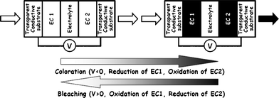 | ||
| Fig. 1 Working principle of an electrochromic device.1 | ||
As current collectors and electronic conductors, n-type Transparent Conductive Oxides (TCOs) on mineral glass or plastic film are by far the most prevalent system in light-modulating devices.2,3 TCO thereby mostly refers to In2O3:Sn (ITO) and SnO2:F (FTO), produced via physical (PVD) and chemical vapor deposition (CVD), respectively. A large variety of substances can be employed as electrochromic materials (EC 1 and EC 2 in Fig. 1), including inorganic metal oxides (WO3, MoO3, NiOx, IrOx, mixed vanadium oxides, etc.), organic redox dyes, conducting polymers, as well as inorganic and organometallic complexes (metallopolymers, Prussian Blue, etc.). The electrolyte, in its role as pure ion conductor and electronic insulator, can either be organic or inorganic, and may be liquid or solid (e.g. solid polymer electrolytes based on polyethylene oxides or polymer gel electrolytes containing organic carbonates). As ions, protons (H+) or lithium ions (Li+) are generally preferred.
The first (1988) and probably most successful commercialization of EC devices concerned self-darkening rear-view mirrors based on organic redox dyes for automotive use (GENTEX Corp.; technology not considered in this study). The French company SAINT GOBAIN-SEKURIT entered the automotive market in 2008 with an all-solid-state EC device serving as a sunroof window for the Ferrari Super America. Smart windows or chromogenic glazing for architectural use were first introduced by PILKINGTON/FLABEG GmbH in the early 2000s and are now being produced and sold by Germany's ECONTROL-GLAS GmbH and other companies, mainly from the US (SAGE Electrochromics Inc.) and Japan (ASAHI Glass). All window products are based on sputter-deposited WO3 as the cathodic electrochromic layer (EC 1 in Fig. 1). However, the German technology transfer company GESIMAT has been proposing a technological alternative based on electrodeposited EC layers. An important technology that is competitive with EC is liquid crystal glazing, e.g., PRIVA-LITE® from SAINT GOBAIN-SEKURIT. A comprehensive review of electrochromism and electrochromic devices is given in ref. 4.
LCA methodology
The LCA methodology is illustrated in Fig. 2. In the present study, only commercially and technically viable devices constituting clear technological benchmark systems have been considered (Benchmarks 1a/b to 4). It is supposed to provide – from an LCA point of view – decision support for research and development on electrochromic/-tropic smart windows (or other types of light-modulation applications) and anticipate possible environmental problems concerning the production, use, and end of life of these products. It may also serve as a basis for the comparison of current smart shading technologies in terms of their ecological impact.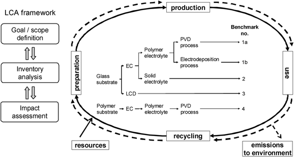 | ||
| Fig. 2 LCA framework,5,6 overview of investigated benchmark systems. | ||
The main functional unit of the present assessment shall be one unit of an electrochromic/-tropic shading device, i.e., one piece of product, 20 cm × 30 cm in size. The system boundaries are cradle to gate, thus comprising production (including the whole value chain), the supply of all chemical precursors, operating supplies, auxiliary materials, energy sources etc. It is planned to extend the system boundaries to cradle to grave at a later stage, then including the use phase and the end of life/recycling of the products as well.
Summary of LCA goal (environmental assessment):
• Environmental benchmark of electrically switchable shading devices according to ISO standard specifications 14![[thin space (1/6-em)]](https://www.rsc.org/images/entities/char_2009.gif) 040 and 14
040 and 14![[thin space (1/6-em)]](https://www.rsc.org/images/entities/char_2009.gif) 044;5,6
044;5,6
• Identification of environmental strengths, weak points, and optimization potential to develop an internal R&D-specific optimization strategy for new devices.
Summary of LCA scope (environmental assessment):
• Functional unit: 20 cm × 30 cm = 0.06 m2;
• System boundary: cradle to gate (assumptions: use phase and end of life: no significant differences between benchmarks, hence neglected);
• Life Cyle inventory data basis: literature and patent research about benchmark systems and their production routes (see Fig. 3–7), use of LCA software system and data basis GaBi, European Life Cycle data base (ELCD),7 ecoinvent data base,8 and LCS calculations (modeling of surface-treatment processes PVD, CVD, and electrodeposition with available industrial process technology information);
• The environmental indicators (impact categories) used are described in Table 1;
• Review: internal technical review of benchmark systems only; comparison and validation of environmental results with earlier related study.9
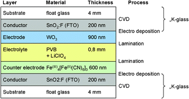 | ||
| Fig. 4 Benchmark 1b: FTO glass substrate, polymer electrolyte, EC films prepared via electrodeposition.30 | ||
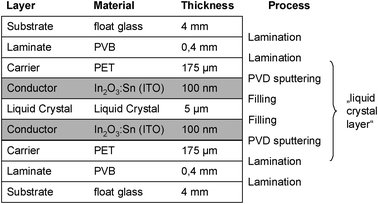 | ||
| Fig. 6 Benchmark 3: Active film laminated between glass panes, PDLC type.24 | ||
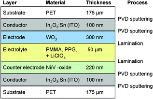 | ||
| Fig. 7 Benchmark 4: ITO-coated polymer substrate, polymer electrolyte, EC films prepared via PVD.21,22 | ||
| Parameter Life Cycle Inventory | Unit | Description | Examples |
|---|---|---|---|
| Primary energy (PE) | MJ | Total of heating values of non-renewable and renewable energy used | Crude oil, natural gas, hydro power, etc. |
| Parameter Life Cycle Impact Assessment | Unit | Description | Examples |
|---|---|---|---|
| Abiotic resource depletion potential (ADP) | kg Sb-equiv. | Use of non-renewable resources | Crude oil, metal ores |
| Greenhouse warming potential (GWP) | kg CO2-equiv. | Emissions to air which influence the heat balance of the atmosphere | CH4, CO2 |
| Photochemical ozone creation potential (POCP) | kg ethene-equiv. | Emissions to air which act as ozone creators at ground level | HCs |
| Acidification potential (AP) | kg SO2-equiv. | Emissions to air which create acidification of rain water | NOx, SO2 |
| Eutrophication potential (EP) | kg [PO4]3−-equiv. | Overfertilization of water and soil | P- and N-compounds |
Many impact categories have been published, but only a few are generally and globally accepted. On a regular basis, the Institute of Environmental Sciences – Leiden University (CML) publishes compilations of its own, externally developed characterization and normalization factors10 that may be used to show environmental impacts of several inventory categories. They constitute one of the two most used sets in LCA practice and are summarized in Table 1.
The choice of impact categories should generally aim towards sustainable development, preserving resources, global protection of the eco-sphere, protecting human health, and the stability of ecosystems.11,12
The European Parliament and Council published The Sixth Environment Action Programme of the European Community,13 from which the impact categories used here are mainly deduced. The environmental priorities within this program are climate change, nature and biodiversity, environment and health, and natural resources and wastes. For the quantified reduction goals for emissions in the European Union see ref. 14–17. Resource depletion is measured here as depletion of non-renewable energy resources (primary energy) in [MJ]. Since the layers of EC devices also contain rare elements such as critical metals, the Abiotic Resource Depletion Potential (ADP) is taken into account as a second category for resource depletion, where non-energy resources are included.18,19
Description of benchmark systems investigated
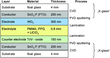
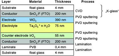
Five archetypical benchmark systems have been chosen (Fig. 2) and modeled by means of the LCA software GaBi.20 The systems are further detailed in terms of types of substrate, electrolyte, and EC materials in Fig. 3–7. Benchmarks 1a/b–3 address glass based variable transmittance devices, whereas Benchmark 4 describes a plastic-film based EC device.21,22 Benchmark 3 concerns an electrotropic polymer-dispersed liquid crystal (PDLC) technology. The liquid crystals are embedded in a polymer matrix, the structure of which produces modulated light scattering also known as the Christiansen effect.23 PDLC films are not used stand-alone, but integrated in glass doors, windows, or room dividers (so-called privacy glazing),24 which has been taken into account for the assessment (Fig. 6). Benchmarks 1a/b and 2 concern EC systems comprising an ion-conducting polymer electrolyte and a sputter-deposited solid proton conductor, respectively, located between the main EC film and the counter electrode layer. Benchmark 2 is sometimes also referred to as all-solid-state technology based on a monolithic stack of thin films deposited on a single substrate.25–27 Benchmarks 1a and 1b further distinguish between two different well-established deposition processes for EC films, i.e. PVD28,29 and wet-chemical electrodeposition.30 Benchmarks 1a and 4 resemble each other in terms of EC materials (inorganic metal oxides), deposition processes (PVD), and type of electrolyte (polymeric ion conductor), but differ in the type of substrate (FTO glass vs. ITO PET).31The authors put emphasis on the statement that the given device configurations do not necessarily fully comply with the situation in real existing products or prototypes. They comprise a number of assumptions made to accomplish the modeling tasks and are based on published data and information. Consequently, all models are open for variation of important parameters (toolbox) such as the materials used in substrates and functional layers, the thickness of layers, and material deposition and lamination processes.
Smart window half-cells based on tungsten or nickel oxides must usually be pre-treated (‘charged’, ‘pre-inserted’) before they can be assembled to form a full device. Besides direct sputtering of lithiated compounds,33 pre-lithiation34 or ozone exposure35 have been proposed to accomplish that. It is emphasized that the energetic contribution of any of such activation steps has not been taken into account in the present study.
For the evaluation of environmental benignancy for products and processes, a comprehensive benchmark analysis was performed. All materials and processes were called into question with regard to their potential effect on health and the environment. A clear focus was laid on environmentally benign manufacturing. It is known that decisions made within the initial stages of a product's development are anticipated to have the furthest reaching economic, ecological, and employment effects.
Results and discussion
In the following, the environmental assessment results shall be detailed with a focus on primary energy demand. Fig. 8 gives a brief overview of the data obtained. To demonstrate the environmental relevance, all investigated materials and their production processes have been normalized to the same layer thickness of 1 μm. The reference point is float glass and the normalized parameter is the primary energy demand.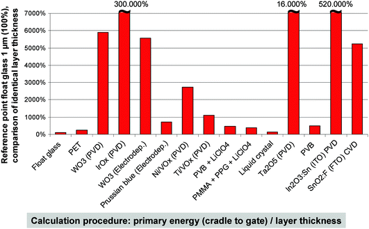 | ||
| Fig. 8 Specific importance of the different materials employed in the selected types of light-modulation devices. | ||
From Fig. 8, the following statements can be derived:
• IrOx and ITO clearly have the highest ecoprofiles due to extensive resource extraction and material processing steps. Sputtering (employed for these materials) is an energy-intensive deposition process. However, the usually rather low layer thickness these materials are applied with may put into perspective the impact on the entire benchmark system. In other words, low consumption of a material with high embodied energy may result in lower overall resource depletion compared to high consumption of a material with low embodied energy.
• WO3 and Ta2O5 have high ecoprofiles, too, but can be produced in a more efficient way.
• Polymer materials have relatively low ecoprofiles due to higher efficiency factors during production. As mentioned above, the overall performance is important.
Fig. 9 summarizes the primary energy demand for all benchmarks. The blue columns show the energy demand for the device manufacturing processes while the red columns depict the energy associated with the materials employed.
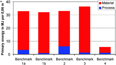 | ||
| Fig. 9 Primary energy demand per functional unit. | ||
In considering primary energy use, it is apparent that while the manufacturing processes employed (starting from the raw materials) are of some importance, the materials used (including the substrates) play a more significant role. This can be demonstrated comparing Benchmarks 1a and 1b. Both systems are based on tungsten oxide as the active EC material but use different deposition processes. The process of electrodeposition in Benchmark 1b clearly consumes less energy than the PVD process in Benchmark 1a. However, this is compensated for by the higher thickness of the electrodeposited layers, resulting in a virtually identical primary energy value for the wet-chemical approach 1b. In contrast to that, Benchmark 2 shows a comparatively high energy demand for the all-solid-state process comprising the subsequent sputtering of three thin films (2 EC films plus an inorganic ion conducting film) to a monolithic multilayer structure. However, because of the very low film thickness typical for this technology, the total energy demand is almost identical to Benchmark 1a, i.e., the system with sputter-deposited EC films and a polymer electrolyte.
In Benchmark 3, two lamination steps to glass panes and the use of ITO as a conductor in the PDLC film lead to high energy requirements in the material category. Benchmark 4 is different from the other benchmarks, since it does not employ a glass substrate but rather a thin PET film. As the preparation of FTO glass is a highly energy- and resource-intensive process, the use of a plastic substrate results in much lower primary energy demand that would more than compensate for any other effects such as a change in the process. The high environmental impact of the glass substrate is also evident from Fig. 10, where the contributions of the substrates and the functional layers are separated.
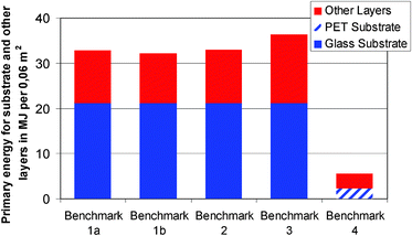 | ||
| Fig. 10 Primary energy demand per functional unit, separated into the contributions of the substrates and the other layers (i.e. the electro-active films and the electrolytes). | ||
There was little difference between the tendencies found for the impact categories in comparison to the primary energy. Fig. 11 provides an overview illustrating this. Benchmarks 1a, 1b, 2, and 3 generally have a higher impact than Benchmark 4. The ratios between the different categories are almost identical; there is only minor variation. The main impact category of the abiotic resource depletion potential (blue columns) is followed by the acidification potential (orange columns) and the global warming potential – also known as greenhouse effect potential – (red columns), with this last category showing approximately half the level of person equivalents of the ADP. The photochemical ozone creation potential has a less marked impact. For the plastic based Benchmark 4, the picture was slightly different as the POCP was higher than the GWP at around 50% of the ADP. However, since the absolute POCP value was still low compared to the other benchmarks, this is of no further relevance. The environmental problem area of eutrophication may generally be considered of minor importance and thus omitted in the future discussion.
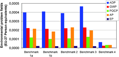 | ||
| Fig. 11 Environmental problem fields normalized to EU27 per functional unit. ADP: Abiotic Resource Depletion potential; GWP: Global Warming potential, POCP : Photochemical Ozone Creation potential, AP: Acidification potential, EP: Eutrophication Potential. | ||
There are a number of important findings from Fig. 9–11:
• The process of manufacturing the light-modulation devices from the raw materials is of high environmental importance. This makes the choice of appropriate manufacturing technology highly relevant.
• The substrate is of high environmental importance. The use of glass sheets that are as thin as possible or plastic film substrates is strongly preferable from an energy/environmental point of view.
• The layers of conductors and electrodes are generally of high specific environmental importance. They should be kept as thin as possible when designing devices.
• The use of ITO as transparent conductor more than compensates for any other effect from an environmental point of view. Hence any discussion of the pros and cons of different deposition techniques in terms of energy depletion might be redundant as long as ITO is used as the transparent conductor.
• The environmental impact of the EC layers in tungsten oxide based devices is much higher than the impact of the polymer electrolytes. This is remarkable keeping in mind that the EC and polymer electrolyte layers differ strongly in their layer thicknesses (usually one to two orders of magnitude).
• The use of an inorganic proton electrolyte (hydrated Ta2O5) does not significantly change this situation, despite a high energy demand for the related sputter-deposition process, due to the low layer thickness usually employed for such ion conductors.
• Among the EC layers, the working electrode material tungsten oxide (where applicable) has at least a two-fold higher impact than usual counter electrode materials such as nickel or vanadium oxides. This explicitly does not hold for iridium oxide, which has an extremely high impact.
• Prussian Blue is by far the most favorable counter electrode material in terms of environmental impact (of those materials modeled in this study).
• The most important environmental problem areas are global warming, abiotic resource depletion, acidification, and photochemical ozone creation.
Syrrakou et al.9 published a study on the environmental impact of electrochromic glazing production in 2005. In comparison to the present work, the scope of this earlier study is smaller and based on primary energy only (Life Cycle Inventory). The glass demand of the functional unit is comparable to the benchmarks in the present study. However, in the latter, the sheet glass ecoprofile (meaning the main impact factor in the whole ecoprofile) is about 75% higher, which can be attributed to the availability of up-to-date LCA data and first-hand information from glass manufacturers confirming the higher values. Syrrakou et al. outline the material production routes in a detailed way but do not provide concrete details concerning energy or material depletion, except in glass production. Moreover, no counter electrodes are modelled, which may account for differences in data reported; in particular concerning the high energy demand of some usual counter electrode materials.
Conclusion
The environmental assessment performed on electrically controlled light-modulation benchmark devices (‘smart windows’) clearly highlights those EC materials and processes that are favorable from an environmental and energy demand point of view. Besides the primary energy demand for all materials and processes, it highlights further environmental problem areas that are becoming more and more important against the background of the current lively discussion on greenhouse-gas emissions and the climate change associated with them.It was shown that it makes a tremendous difference in terms of resource depletion and environmental impact whether mineral glass or plastic film is used as the substrate in EC devices. As regards resource depletion, the use of glass may even more than compensate for the perceived positive effect of wet-chemical processing. The use of ITO as transparent conductor must be proposed for discussion if the energy demand of competing processes is taken into consideration. The study provides strong support for the need to find alternative TCO materials, ideally applicable to plastic film.
The benchmark toolbox that was developed is open to the variation of important parameters such as the materials used in substrates and functional layers, the thickness of layers, and the type of material deposition and lamination processes, and it can be adapted at any time according to new developments. It is planned to continue this work focusing on stand-alone plastic-film based chromogenic devices, for instance those employing conducting polymers and nanomaterials as active components.36–39 These approaches have attracted increasing attention in the community in recent years as a way of addressing the demand for a cost-effective, light-weight, and retrofittable technology for light and heat modulation, for example in aircraft cabins.
It is hoped that, in the future, the environmental impact concerning the production, use, and end of life of up-and-coming smart window technology can be traded-off against their prospects to lower the consumption of energy needed for air-conditioning in buildings and electric vehicles.
Acknowledgements
The research leading to these results received funding from the European Community's Seventh Framework Programme (FP7) under Grant agreement no. 200431 (INNOSHADE).References
- S. Duluard, Thesis, Université de Bordeaux 1, France, 2008 Search PubMed.
- C. -G. Granqvist, Sol. Energy Mater. Sol. Cells, 2007, 91, 1529 CrossRef CAS.
- G. J. Exarkhos and X.-D. Zhou, Thin Solid Films, 2007, 515, 7025 CrossRef.
- P. M. S. Monk, R. J. Mortimer and D. R. Rosseinsky, Electrochromism and Electrochromic Devices, CambridgeUniversity Press, 2007 Search PubMed.
- ISO 14040: Environmental management – Life cycle assessment – Principles and framework, 2006, International Organisation for Standardisation (ISO), Geneve.
- ISO 14044: Environmental management – Life cycle assessment – Requirements and guidelines, 2006, International Organisation for Standardisation (ISO), Geneve.
- European Life Cycle data base, www.lct.jrc.ec.europa.eu.
- Ecoinvent data v2.2, www.ecoinvent.ch, 2011.
- E. Syrrakou, S. Papaefthimiou and P. Yianoulis, Sol. Energy Mater. Sol. Cells, 2005, 85, 205 CrossRef CAS.
- Centre of Environmental Science – Leiden University (CML): Characterisation and normalisation factors, Leiden, 2001.
- J. Kreißig, M. Baitz, M. Betz, P. Eyerer, J. Kümmel and H.-W. Reinhardt, Leitfaden zur Erstellung von Sachbilanzen in Betrieben der Steine-Erden-Industrie, Bundesverband Steine + Erden, Frankfurt, 1997 Search PubMed.
- ENQUETE- Kommission “Schutz des Menschen und der Umwelt“ des Bundestages (Hrsg.): Verantwortung für die Zukunft - Wege zum nachhaltigen Umgang mit Stoff- und Materialströmen, Economica Verlag, Bonn, 1993.
- EU: DECISION No 1600/2002/EC OF THE EUROPEAN PARLIAMENT AND OF THE COUNCIL of 22 July 2002 laying down the Sixth Community Environment Action Programme.
- UNEP: The Montreal Protocol on Substances that Deplete the Ozone Layer, published 2000 by Secretariat for The Vienna Convention for the Protection of the Ozone Layer & The Montreal Protocol on Substances that Deplete the Ozone Layer; United Nations Environment Program; Nairobi, Kenya.
- EU: REGULATION (EC) No 2037/2000 OF THE EUROPEAN PARLIAMENT AND OF THE COUNCIL of 29 June 2000 on substances that deplete the ozone layer.
- UN ECE: The 1999 Gothenburg Protocol to Abate Acidification, Eutrophication and Ground-level Ozone. Convention on Long-range Transboundary Air Pollution.
- UNFCCC: Kyoto Protocol to the United Nations framework convention on climate change, 1997.
- G. Huppes et al. Abiotic resource depletion in LCA, Ministerie van Verkeen en Waterstraat of the Netherlands, Amsterdam, 2002 Search PubMed.
- J. B. Guinee, Handbook on life cycle assessment, Kluwer Academic Publisher, Dordrecht, 2002 Search PubMed.
- PE International AG: GaBi Software and data base for Life Cycle Engineering, Echterdingen, 2011.
- E. J. Widjaja, G. Delporte, F. Vandevelde and B. Vanterwyngen, Sol. Energy Mater. Sol. Cells, 2008, 92, 97 CrossRef CAS.
- A. Azens, E. Avendano, J. Backholm, L. Berggren, G. Gustavsson, R. Karmhag, G. A. Niklasson, A. Roos and C.-G. Granqvist, Mater. Sci. Eng., 2005, B 119, 214 CrossRef.
- C. M. Lambert, Society of Vacuum Coaters, Annual TechCon Proceedings, 1995 Search PubMed.
- C. M. Lampert, Sol. Energy Mater. Sol. Cells, 2003, 76, 489 CrossRef CAS.
- F. Beteille, Ph. Boire and J.-C. Giron, Proc. of SPIE – The International Society for Optical Engineering, Switchable Materials and Flat Panel Displays (ed. C. M. Lampert), 1999, Denver, Colorado Search PubMed.
- S. Taunier, C. Guery and J.-M. Tarascon, Electrochim. Acta, 1999, 44, 3219 CrossRef CAS.
- Y. Sone, A. Kishimoto and T. Kudo, Solid State Ionics, 1994, 70–71, 316 CrossRef CAS.
- C.-G. Granqvist, Electrochim. Acta, 1999, 44, 3005 CrossRef CAS.
- H. Wittkopf, Vak. Forsch. Prax., 2010, 22, 26 CrossRef CAS.
- A. Kraft, M. Rottmann and K.-H. Heckner, Sol. Energy Mater. Sol. Cells, 2006, 90, 469 CrossRef CAS.
- R. Baetens, B. P. Jelle and A. Gustavsen, Sol. Energy Mater. Sol. Cells, 2010, 94, 87 CrossRef CAS.
- E. Masetti, F. Varsano, F. Decker and A. Krasilnikova, Electrochim. Acta, 2001, 46, 2085 CrossRef CAS.
- F. Michalak, K. von Rottkay, T. Richardson, J. Slack and M. Rubin, Electrochim. Acta, 1999, 44, 3085 CrossRef CAS.
- Y. Ye, J. Zhang, P. Gu and J. Tang, Sol. Energy Mater. Sol. Cells, 1997, 46, 349 CrossRef CAS.
- A. Azens and C.-G. Granqvist, J. Solid State Electrochem., 2003, 7, 64 CAS.
- C. Ma, M. Taya and C. Xu, Electrochim. Acta, 2008, 54, 598 CrossRef CAS.
- C.-G. Granqvist, P. C. Lansåker, N. R. Mlyuka, G. A. Niklasson and E. Avendaño, Sol. Energy Mater. Sol. Cells, 2009, 93, 2032 CrossRef CAS.
- 3 M INNOVATIVE PROPERTIES COMPANY, WIPO Patent Application WO 2008/133737 A2.
- FP7 - EU Large Collaborative project INNOSHADE (Innovative switching devices), http://www.innoshade.eu/.
Footnote |
| † A lamination step is needed for connection of the substrate to the all-solid sputtered layers. No information about this step was available. Best guess: 0.4 mm PVB layer common for safety glass and used in Benchmark 3 for the same purpose. |
| This journal is © The Royal Society of Chemistry 2012 |

