Formation of new biosilica-like structures by flow-induced forces
Fangfang
Wang
,
Feng
Jiang
,
Yong
Li
,
Qinrong
Wang
and
Xin
Zhang
*
Department of Chemistry, Science Faculty, Shantou University, Shantou, 515063, China. E-mail: xzhang@stu.edu.cn; Fax: 86 754 82903639
First published on 13th April 2012
Abstract
A bioinspired approach to the synthesis of silica was induced by poly (L-lysine) (PLL) under the presence of a flow dynamic field. We found that the biosilica-like morphologies were controlled by the combination of the molecular weight of PLL and the condition of the hydrodynamic field. The flow dynamic field can provide extra energy to the silica nucleation system and produce new stereostructures of silica. This study established an easy and efficient approach for producing desired biosilica-like structures using an external force field via careful control of the reaction microenvironment.
1. Introduction
The design and fabrication of various inorganic porous materials have attracted considerable research interest because of their wide potential applications in therapeutic, storage, molecular recognition, catalysis, and biomedical fields.1–7 Traditional chemical methods of preparing silica-based materials have resulted in great success;8 however, these chemical synthesis approaches typically require unfavourable synthetic conditions, such as long synthesis times, high costs, and an increased likelihood of being environmentally unfriendly. In contrast, biological organisms, such as diatoms, sponges and grasses, are able to produce a series of complex and elegant silica structures under mild physiological conditions.9–14 Obviously, biomimetic synthesis strategies have many distinctive advantages over traditional chemical synthesis methods. The formation of solid silica structures with precisely controlled morphologies in biological applications is directed by proteins and polysaccharides under mild conditions.15–17 These new approaches can overcome the limitations of chemical methods and provide a powerful paradigm for the construction of complex biological nanostructures.18–20 Thus, exploration and development of a biomimetic synthesis for the preparation of specific inorganic material by a biomimetic design and self-assembly is important.Recent studies have demonstrated that controlling the experimental conditions, such as the chemical and physical conditions can affect the morphology of the silica product during the silica biomineralization process in vitro environment. The application of an external force field, such as electric, magnetic, and flow fields, provides a different route for developing the novel biosilica-like structure. These external fields can promote the controlled formation of biosilica-like structures under mild conditions. However, only a few studies have focused on the influence of external force fields on the silica biomineralization process using PLL as a polymer template. Stone et al.21,22 have studied the influence of chemical and physical conditions. They have indicated that a force field can change the free energy of silica nucleation, resulting in the formation of a new biosilica-like structure. Patwardhan et al.23 have investigated mechanisms controlling inorganic morphologies using poly (L-lysine) in biosilica-like synthesis. They have indicated the possibility of selectively precipitating silica with controllable morphologies using heat.23 In addition, they also combined bioinspired synthesis and continuous flow processing to produce silica materials which were used for entrapping active enzymes and quantum dots.24 Only a few previous studies have investigated the external field effect in the formation of silica morphologies. So the design and synthesis of nanoscale materials with controlled morphologies and structures remain a significant and continuing challenge for researchers.
In this report, we investigate the effects of shear flow on the morphology of biosilica-like structures induced by polypeptides. Although the external field effect on biosilica-like formation has been studied, the controlled formation of biosilica-like morphology using the combination of a polypeptide template and mechanical force has not yet been reported. The experimental results show that the flow-induced microenvironment can control the morphologies and structures in biosilica-like formation. The employed linear shear force appear to direct the transport and deposition of silica when it is formed from a silica precursor by polypeptides. Biosilica-like morphology is demonstrated to be controlled not only by the polypeptide molecular weight, but also by external fields.
2. Experimental section
2.1. Materials
All reagents and poly (L-lysine) hydrobromide (PLL·HBr) (PLL1, molecular weight (Mw) = 1 kDa to 5 kDa; PLL2, Mw = 30 kDa to 70 kDa; and PLL3, Mw = 70 kDa to 150 kDa) were purchased from commercially available sources and used without any further purification. The buffer used was phosphate-buffered saline (PBS, 0.1 M) at pH 7.5. Deionised ultrafiltered (DIUF) water was used for washing the centrifuged samples. Hydrochloric acid (HCl) was used for TEOS prehydrolysis. Nitrogen was used for providing the flow field.2.2. Sample characterization
![[thin space (1/6-em)]](https://www.rsc.org/images/entities/char_2009.gif) :
:![[thin space (1/6-em)]](https://www.rsc.org/images/entities/char_2009.gif) 1 volume ratio of PLL/PBS mixture to TEOS solution. The samples (300 μL) were loaded into a 1 mm path length quartz cuvette to record CD data. Data points for the wavelength-dependent CD spectra were recorded from 240 nm to 185 nm (speed 50 nm min−1) at every nanometer with a 1-nm bandwidth. The CD spectra were immediately recorded after mixing the silica acid as the reaction happened immediately and the solution quickly became opaque. Greenfield has proven that both the β form and random coil have very low ellipticities equal to approximately −4 000 deg cm2 dmol−1 at 208 nm.25 The α-helix has an extremum at this point equal to approximately −33 000 deg cm2 dmol−1. Thus, for a quick estimate, the percentage of α-helix can be calculated from α helix (%) = ([θ]208 − 4 000)/(33 000 − 4 000) × 100%, where [θ]208 is the molar ellipticity at 208 nm.
1 volume ratio of PLL/PBS mixture to TEOS solution. The samples (300 μL) were loaded into a 1 mm path length quartz cuvette to record CD data. Data points for the wavelength-dependent CD spectra were recorded from 240 nm to 185 nm (speed 50 nm min−1) at every nanometer with a 1-nm bandwidth. The CD spectra were immediately recorded after mixing the silica acid as the reaction happened immediately and the solution quickly became opaque. Greenfield has proven that both the β form and random coil have very low ellipticities equal to approximately −4 000 deg cm2 dmol−1 at 208 nm.25 The α-helix has an extremum at this point equal to approximately −33 000 deg cm2 dmol−1. Thus, for a quick estimate, the percentage of α-helix can be calculated from α helix (%) = ([θ]208 − 4 000)/(33 000 − 4 000) × 100%, where [θ]208 is the molar ellipticity at 208 nm.
2.3. Biosilica-like preparation
Details of the experimental procedure have been previously reported.9,26 A stock solution of 1 mM HCl in DIUF water was prepared and used for all reactions. For each experiment, the TEOS solution in 1 mM HCl and the polypeptide solution in buffer were always freshly prepared. Silicic acid was prepared by the ultrasonication of 200 μL of TEOS in 1.3 ml HCl (1 mM) for 30 min. The PLL solution (2.5 mg mL−1) was premixed with PBS (0.1 M) at pH 7.5 before the addition of the silica precursor solution. The volume ratio of PLL to the silica precursor solution was 4![[thin space (1/6-em)]](https://www.rsc.org/images/entities/char_2009.gif) :
:![[thin space (1/6-em)]](https://www.rsc.org/images/entities/char_2009.gif) 1. A flow hydrodynamic field which drives the formation of biosilica-like morphology was generated in a lab-build flow reactor with dimensions of 1.5 cm and a length of 5 cm (Fig. 1). The PLL solution was injected into the reaction vessel, and then the silicic acid was added after the nitrogen was flowed into the reactor for five minutes. We controlled the flow rate by adjusting the flow control valve to keep the designed flow conditions in the reactor during the reaction periods. After the desired reaction time had elapsed, the samples were centrifuged at 14
1. A flow hydrodynamic field which drives the formation of biosilica-like morphology was generated in a lab-build flow reactor with dimensions of 1.5 cm and a length of 5 cm (Fig. 1). The PLL solution was injected into the reaction vessel, and then the silicic acid was added after the nitrogen was flowed into the reactor for five minutes. We controlled the flow rate by adjusting the flow control valve to keep the designed flow conditions in the reactor during the reaction periods. After the desired reaction time had elapsed, the samples were centrifuged at 14![[thin space (1/6-em)]](https://www.rsc.org/images/entities/char_2009.gif) 000 rpm for 10 min. A white solid precipitated in the tubes. The liquid supernatant was removed, and the precipitate was redispersed in the DIUF water three times to remove unreacted TEOS and unconsumed polypeptides. This dispersion was further diluted, and a few drops of solution were placed on SEM sample holders. The samples were left to dry under ambient conditions.
000 rpm for 10 min. A white solid precipitated in the tubes. The liquid supernatant was removed, and the precipitate was redispersed in the DIUF water three times to remove unreacted TEOS and unconsumed polypeptides. This dispersion was further diluted, and a few drops of solution were placed on SEM sample holders. The samples were left to dry under ambient conditions.
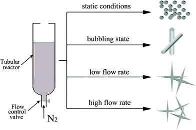 | ||
| Fig. 1 The different external flow conditions: under static conditions; in the bubbling state; at a low flow rate; and at a high flow rate. | ||
3. Results and discussion
The biomineralization of silica templated by amino acids and cationic PLL has attracted extensive research interest.23,27–32 The basic experimental route is that a PLL/PBS mixture is added to silicic acid to produce versatile silica morphologies under different flow conditions. To study the influence of an external field (a flow field, in the present text), we used four flow field conditions, namely, the static condition, the bubbling state, the low flow rate, and the high flow rate. Considering the influence of the polypeptide Mw, we used three kinds of Mw’s, namely, PLL1 (1 kDa to 5 kDa), PLL2 (30 kDa to 70 kDa), and PLL3 (70 kDa to 150 kDa). Elucidating which factor influences the morphologies of the silica produced by PLL is more accurate when we solely considered the effects of the external field or the polypeptide Mw’s. The PLL concentration, silicic acid concentration, and reaction time were fixed, whereas the studied factor was varied.Fig. 2a to 2d show typical SEM images of the biosilica-like structures prepared using the PLL template with a Mw of 30 kDa to 70 kDa in the absence and presence of a flow dynamic field. Fig. 2a shows a typical sphere structure in the absence of a flow dynamic field. Fused spheres interlocked with each other to form a reticulated structure. Fig. 2b to 2d show the different structures obtained in the presence of a flow dynamic field. A monaxon-like morphology (Fig. 2b) was obtained when gas bubbles were passed though the reaction solution. This morphology can find its prototype in nature as some demosponges, monaxons and strongyles also have similar structures. When the gas flow rate was slightly increased, a sheet-like structure was observed (Fig. 2c). These sheet-like structures tended to lock together and fuse into a large silica sheet. These structures changed to a flower-like structure which formed by the small sheet folded over vertically (Fig. 2d) when a higher flow rate was used. Obviously, these silica sheets were smaller than their counterparts in Fig. 2c. Therefore, the external field indeed changed the morphologies of silica induced by PLL2.
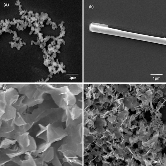 | ||
| Fig. 2 SEM images of biosilica-like produced by PLL2 under different external flow fields (a) under static conditions, (b) in the bubbling state, (c) at a low flow rate, and (d) at a high flow rate. | ||
A comparison of the morphologies of the different silica structures formed through various Mw’s of PLL under the same external field is meaningful. When a small Mw of PLL1 (1 kDa to 5 kDa) was used, only spherical structures were obtained in the absence and presence of the flow dynamic field, such as those shown in Fig. 3. The silica nanospheres fused together and the average diameter of the sphere became smaller with an increase in the flow rate. Compared with PLL2 (Fig. 2), the morphologies of the resulting silica produced by PLL1 did not make any obvious transition. Nevertheless, this result was consistent with previous reports, where PLL chain lengths between 100 and 840 amino acid residues have resulted in the formation of fused silica platelets. In contrast, PLL of chain lengths < 100 amino acids have given rise to a network of fused silica spheres.30,31 The Mw of PLL1 was 1–5 kDa, namely an average of 23 amino acid residues, which was so small that it could not form an intricate structure although a flow dynamic field was used.
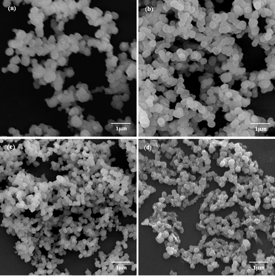 | ||
| Fig. 3 SEM images of biosilica-like structures produced by PLL1 under different external flow fields (a) under static conditions, (b) in the bubbling state, (c) at a low flow rate, and (d) at a high flow rate. | ||
To study the influence of a force field on the silica structure, a much larger Mw of PLL3 (70 kDa to 150 kDa) was used. When we compared the morphologies of silica directed by PLL3 under different external fields, we found different results compared with those reduced by PLL1 and PLL2. Fig. 4a to 4d show the morphologies of the biosilica-like structure induced by a much larger Mw PLL3 (70 kDa to 150 kDa) at different external conditions. A silica sphere-based reticulated skeleton was obtained in the absence of the flow dynamic field. When the nitrogen gas flow rate was extremely low, the nitrogen gas passes through the reaction solution in the bubble state, and a hypersilicified tylostyle-like structure with some nanoparticles doping. The tylostyle-like structure appears just like a miniature edition of Suberites tylobtusa according to the image offered by Uriz et al.10 With the gas flow rate slightly increased, a hexactine-like structure made up of sheets instead of the spicules was observed in Fig. 4c. The majority of them were vertically cross overlapped, while the rest were less strictly vertical. More hexactine-like structures formed when the flow rate was further increased. The size of the hexactine-like structures was smaller than those produced at the low flow rate and the amount of less vertical structures increased by comparing with Fig. 4c and 4d. By comparing the three different Mw’s (PLL1 to PLL3) under different flow states, we derived a conclusion that biosilica-like morphologies formed depending on the combination of the PLL Mw and the intensity of the flow hydrodynamic field.
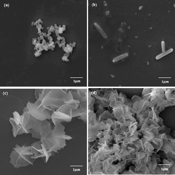 | ||
| Fig. 4 SEM images of biosilica-like produced by PLL3 under different external flow fields (a) under a static condition, (b) in the bubbling state, (c) at a low flow rate, and (d) at a high flow rate. | ||
To understand the formation mechanism of the biomimetic synthesis of silica induced by PLL under a flow hydrodynamic field, the constant growth process of monaxon-like structure was investigated by time-resolved SEM. Fig. 5 shows the nucleation of the silica acid precursor induced by PLL in the flow conditions at different times from 5 min to 1 h. As shown in Fig. 5a, tiny nanoparticles formed during the initial stages of mineralization. Microsphere transport, orientation, and assembly then occurred to form the elongated structure under the effect of the flow hydrodynamic field (Fig. 5b). Finally, the silica elongated structures further formed a monaxon-like morphology by directional growth (Fig. 5c and 5d). This result is similar to the biosilicification process in the nature. As known to all, the biosilicification process was very common in the sponges. There are two types of silicification mechanisms in sponges: one is enzymatic (silicatein-based) and nonenzymatic silicification, the other is self-assembling (chitin- and collagen-based) silicificaton.10 In the present study, the PLL served as catalytic sites to promote the hydrolysis and condensation of tetraethoxysilane, just like enzymatic silicification in nature. Meanwhile, the peptides self-assembled into a complex secondary structure to tune the formation of designed silica material. The self-assembling progress was tracked in situ by laser scanning confocal microscopy (LSCM) and liquid atomic force microscopy (liquid-AFM) in our former research.33 Therefore, all these results could provide evidence that the external flow field directed the silica mineralization to form a specific structure, and can help elucidate the formation mechanism of monaxon-like silica morphology.
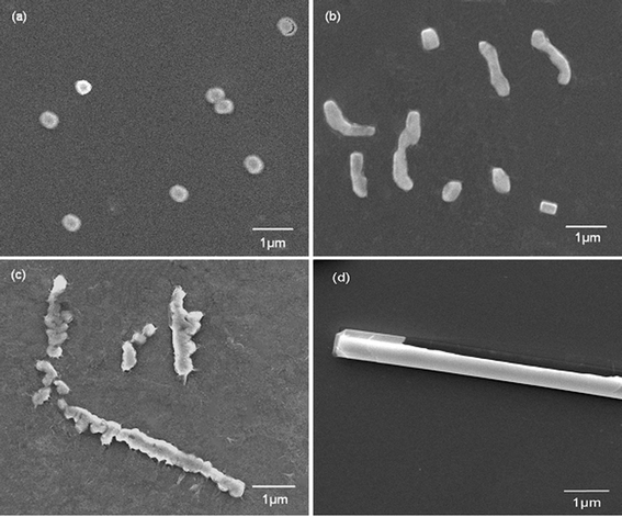 | ||
| Fig. 5 SEM images of biosilica-like structures produced by PLL with reaction times of (a) 5 min, (b) 10 min, (c) 15 min, and (d) 1 h. | ||
The experimental results demonstrated that the biosilica-like morphologies formed can be controlled by the flow dynamic field. After the silica nanoparticles formed, they were transported and deposited to form highly organised and complex structures induced by a mechanical force field. The force field may have enhanced the ability of mineralising systems to form novel oriented structures.23 These silica spheres fused into three-dimensional silica structures directed by the cationic charged macromolecule PLL in the presence of a hydrodynamic field. Therefore, a higher stereo silica structure was obtained when a stronger flow field was used. This finding may imply that the external flow field can provide extra energy to the silica nucleation, which promoted the silica to form more stereo structures in the subsequent biomineralization process. These analyses were consistent with a previous study,21 and suggested that the free energy of silica nucleation can be changed by applied force fields, thereby leading to a change in the silica structure (from spherical to hexagonal).
We can understand the correlation mechanism by investigating the relationship between the PLL secondary structure and biosilica-like structures formed under different externally applied force fields. We performed CD spectroscopy to analyse PLL secondary conformations under different flow conditions. A previous study has demonstrated that the PLL secondary structure plays a critical role in silica morphologies. The random coil secondary structure of PLL tends to form a template of a network of spherical nanoparticles, whereas the helical conformation tends to direct hexagonal silica platelets.27
Fig. 6 shows the CD spectra of PLL2 under different external fields. As illustrated in Fig. 6a, a solution of PLL2 in the absence of a flow force yields a CD spectrum with a minimum at approximately 198 nm, indicative of a random coil conformation. Fig. 6b demonstrates that in a CD spectrum, there was a small transition from random coil to α-helix when nitrogen gas was passed though the reaction solution as bubbles. At the same time, the produced silica transformed from a spherical to a monaxon-like morphology. Further increasing the flow rate resulted in relatively obvious changes in the PLL2 both at low and high flow rates. Both CD spectra underwent a coil–helix transition with the two characteristic peaks of helical conformation at 205 and 226 nm (Fig. 6c and 6d). CD spectra analysis using a standard algorithm indicated that the helical contents of the CD spectrum of PLL2 increased from 21% under a static condition to 34% at the low flow rate and 43% at high flow rate, respectively. At the same time, the resulting silica morphologies changed from a network of silica spheres to monaxon-like, then to sheet-like and finally flower-like structures. These results implied that the external hydrodynamic field had indeed altered the secondary structure of the polypeptide, which further influenced the produced silica morphologies.
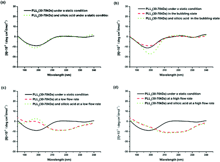 | ||
| Fig. 6 CD spectra of PLL2 under different external fields: (a) under static conditions, (b) in the bubbling state, (c) at a low flow rate, and (d) at a high flow rate. | ||
Comparing the CD spectra of the PLLs with various Mw’s under different flow intensities can help elucidate the mechanism involved. Fig. 7 shows the CD spectra of PLL1. A coil–helix structure transition was not observed even at high flow intensity. This CD result was consistent with the SEM result (Fig. 3), in which the short-chain PLL1 failed to form a helical structure. Only a spherical structure was obtained in the absence and presence of the flow dynamic field. Fig. 8a shows that the CD spectra of a larger-Mw PLL3 (70 kDa to 150 kDa) did not undergo an essential conformation transition under the static condition, similar to the former two Mw’s. The resulting silica morphologies produced by these peptides were networks of nanoparticles. However, when gas was passed through the solution in bubble form, conformation transition occurred, as evidenced by the peak shift from the at minimum around 198 nm to the minimum at around 216 nm. At the same time, the silica produced by PLL3 also changed from spherical to a hyper-silicified tylostyle-like structure. Further increasing the flow rate resulted in two peaks at around 208 and 222 nm, which are the characteristic α-helix peaks. The hexactine-like structure observed in PLL3 was more three-dimensional than the counterpart produced by PLL2. A more hexactine-like structure can be obtained with an increased gas flow rate. CD spectra analysis also indicated that the helicity of PLL increased from 22% to 59% at a low flow rate. The helix percentage increased even more from 22% to 64% in the absence of silicic acid, and 70% in the presence of silicic acid at a high flow rate. Generally, the change tendency of the CD spectra of PLL and the resulting silica morphologies were very similar between PLL2 and PLL3, but greatly varied compared with PLL1 and PLL2. As also shown in Fig. 9, the change tendency of the PLL3 growth rate of the α-helix varied with flow conditions and was similar to PLL2 but different to PLL1. At the same time, the resulting silica structures directed by PLL2 and PLL3 changed from silica nanoparticles to tylostyle-like or monaxon-like structures, then to sheet-made hexactine-like morphologies, finally to much smaller hexactine-like silica. The change in α-helix was much larger for PLL3 than for PLL2, so the silica templated via PLL3 was correspondingly more complicated than PLL2. Nevertheless, the silica produced by PLL1 didn't change and nothing but nanoparticles was found. This was all due to the small change in the growth rate of the α-helix. These results corroborate the supposition that the external flow field can direct the resulting silica morphologies, and that the Mw of the peptides affects the effect of the external flow field. On one hand, with increasing the gas flow rate, the structure underwent a more obvious coil–helix transition in the same peptide. Thus, the resulting silica morphologies tended to be more three-dimensional. A reasonable explanation for this finding would be that the gas flow provides extra energy to the reaction system such that the peptide can form more stereo structures and then induce more complicated silica morphologies. On the other hand, larger-Mw peptides were more easily influenced by the external hydrodynamic field than those with smaller Mw’s. The process of peptide tuning silica precipitation is known to involve electrostatic interactions and hydrogen bonding between the positively charged PLL and the negatively charged silicic acid.34,35 For the lower-Mw PLL1, the unsuccessful conformation transition can be attributed to the fewer number of residues which prevents further chain association.36 The helix structure of the shorter PLL1 is kinetically impossible regardless of sufficient energy provided by the external field. Compared with PLL1, the larger-Mw peptides (PLL2 and PLL3) have more residues to form intricate conformations by intermolecular and intramolecular interactions. Under the external flow field, the peptides can undergo a coil–helix transition more easily. Finally, the peptides can produce different silica morphologies under different external fields.
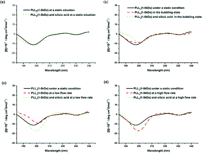 | ||
| Fig. 7 CD spectra of PLL1 under different external fields: (a) under static conditions, (b) in the bubbling state, (c) at a low flow rate, and (d) at a high flow rate. | ||
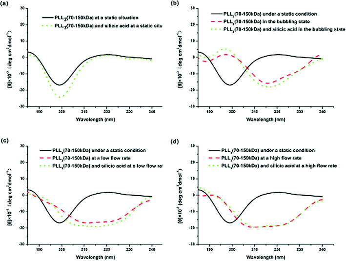 | ||
| Fig. 8 CD spectra of PLL3 under different external fields: (a) under static conditions, (b) in the bubbling state, (c) at a low flow rate, and (d) at a high flow rate. | ||
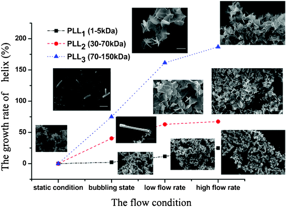 | ||
| Fig. 9 The growth rate of the α-helix of the different molecular weights of Poly-L-lysine and the SEM images of the resulting silica. | ||
We further employed Fourier transformed infrared Spectroscopy (FTIR) to investigate the entrapment of PLL molecules within silica. Fig. 10 shows overlaid spectra from 4000 cm−1 to 400 cm−1. The predominant peak regions arising from PLL were highlighted in the plot and were as follows: 3269 cm−1, attributed to the unprotonated NH2; 3055 cm−1, attributed to the NH3+; as well as 1623 and 1534 cm−1, attributed to the amide I and II bands of the polypeptide. These results implied that the secondary of the poly-L-lysine is α-helix. The hybrid silica (i.e., polypeptide silica composite) displayed three characteristic peaks: –Si–O–Si asymmetric stretching at 1082 cm−1, symmetric stretching at 796 cm−1, and –Si–OH stretching at 967 cm−1. The FTIR analysis demonstrated that PLL molecules were incorporated into the silica structure. These results were also consistent with literature reports and our former research.33,37,38
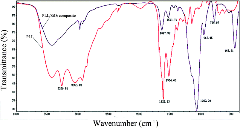 | ||
| Fig. 10 FTIR spectra of PLL3 and PLL3/TEOS composite. | ||
A previous study has demonstrated that biomacromolecules such as PLL can induce the construction and orientation of formed biosilica inorganic materials. The formation of the three-dimensional structure of peptides depends on the peptides used.27 The biosilica-like structure formed upon the transition from random coil to α-helices for the peptide secondary structure. Under static reaction conditions, only large-Mw peptides can be used to form the regular hexagonal structure of biosilica-like morphologies. However, the introduction of a flow field could provide extra energy for silica nucleation, which can affect and promote the formation of novel oriented biosilica-like structures. Under a hydrodynamic field, peptides are allowed to move freely to form a new three-dimensional structure, which induces silica sphere directional growth to form an elongated silica structure.22,31 Depending on the combination of large-Mw PLLs and the hydrodynamic field, the new desired morphology of the biosilica-like structures can be obtained by controlling the reaction microenvironment and using mechanical force. The experimental results showed that the flow hydrodynamic field directed the movement of the silication site, leading to the formation of a changed morphology during the biomimetic synthesis. The method employing a flow hydrodynamic field in the current study can lead to the development of a route to control the formation of biosilica-like structures.
4. Conclusions
The current study demonstrated that the use of a force field can alter and control biosilica-like morphologies during silica biosynthesis induced by polypeptides. The results showed that the Mw of PLL and the force field profoundly influenced the synthesis of biosilica-like morphologies. The resulting biosilica-like structure was controlled not only by the PLL chain length, but also by the hydrodynamic field. When large-Mw PLL was used, the regular hexagonal structure of biosilica-like morphologies could be obtained. The use of a force field can produce new hexagonal morphologies of biosilica-like. The current research elucidates the roles of silica biomineralization templated by polypeptides and an additional external force field for controlling biosilica-like morphologies. An easy and efficient approach for producing desired biosilica-like structures via careful reaction microenvironment reaction control and using an external force field has been established.Acknowledgements
We gratefully acknowledge the National Science Foundation of China (20871080) and Innovation Team Construction Project of Shantou University (ITC11002) for their financial support of this research.References
- W. Q. Cai, J. G. Yu, B. Cheng, B. L. Su and M. Jaroniec, J. Phys. Chem. C, 2009, 113, 14739–14746 CAS.
- Y. F. Zhang, H. Wu, J. Li, L. Li, Y. J. Jiang, Y. Jiang and Z. Y. Jiang, Chem. Mater., 2008, 20, 1041–1048 CrossRef CAS.
- M. Yamanaka, Y. Miyake, S. Akita and K. Nakano, Chem. Mater., 2008, 20, 2072–2074 CrossRef CAS.
- M. C. Zhang, W. Q. Zhang and S. N. Wang, J. Phys. Chem. C, 2010, 114, 15640–15644 CAS.
- H. Xu, Y. M. Wang, X. Ge, S. Y. Han, S. Wang, P. Zhou, H. H. Shan, X. B. Zhao and J. R. Lu, Chem. Mater., 2010, 22, 5165–5173 CrossRef CAS.
- X. F. Yang, H. Tang, K. S. Cao, H. J. Song, W. C. Sheng and Q. Wu, J. Mater. Chem., 2011, 21, 6122–6135 RSC.
- M. S. Toprak, B. J. McKenna, M. Mikhaylova, J. H. Waite and G. D. Stucky, Adv. Mater., 2007, 19, 1362–1368 CrossRef CAS.
- R. Schiller, C. K. Weiss, J. Geserick, N. Husing and K. Landfeser, Chem. Mater., 2009, 21, 5088–5098 CrossRef CAS.
- N. Boury-Esnault and K. Rutzler, Smithsonian Contributions to Zoology, 1997, 596, 1–55 CrossRef.
- M. J. Uriz, X. Turon, M. A. Becero and G. Agell, Microsc. Res. Tech., 2003, 62, 279–299 CrossRef CAS.
- H. Ehrlich, R. Deutzmann, E. Brunner, E. Cappellini, H. Koon, C. Solazzo, Y. Yang, D. Ashford, J. Thomas-Oates, M. Lubeck, C. Baessmann, T. Langrock, R. Hoffmann, G. Wörheide, J. Reitner, P. Simon, M. Tsurkan, A. V. Ereskovsky, D. Kurek, V. V. Bazhenov, S. Hunoldt, M. Mertig, D. V. Vyalikh, S. L. Molodtsov, K. Kummer, H. Worch, V. Smetacek and M. J. Collins, Nat. Chem., 2010, 2, 1084–1088 CrossRef CAS.
- H. Ehrlich, Springer Verlag, 2010, 173–180.
- H. Ehrlich, J. Reitner and V. Thiel, Springer, 2011, 796–808.
- C. C. Perry, S. Mann, J. Webb and R. J. P. Williams, Wiley-VCH, 1989, 223–257.
- N. Kröger and R. Deutzmann, Science, 1999, 286, 1129–1132 CrossRef.
- X. Q. Li, T. T. Yang, Q. Gao, J. J. Yuan and S. Y. Cheng, J. Colloid Interface Sci., 2009, 338, 99–104 CrossRef CAS.
- J. N. Cha, G. D. Stucky, D. E. Morse and T. J. Deming, Nature, 2000, 403, 289–292 CrossRef CAS.
- H. Acar, R. Garifullin and M. O. Guler, Langmuir, 2011, 27, 1079–1084 CrossRef CAS.
- A. Altunbas, N. Sharma, M. S. Lamm, C. Yan, R. P. Nagarkar, J. P. Schneider and D. J. Pochan, ACS Nano, 2010, 4, 181–188 CrossRef CAS.
- K. Tao, J. Q. Wang, P. Zhou, C. D. Wang, H. Xu, X. B. Zhao and J. R. Lu, Langmuir, 2011, 27, 2723–2730 CrossRef CAS.
- F. Rodríguez, D. D. Glawe, R. R. Naik, K. P. Hallinan and M. O. Stone, Biomacromolecules, 2004, 5, 261–265 CrossRef.
- R. R. Naik, P. W. Whitlock, F. Rodriguez, L. L. Brott, D. D. Glawe, S. J. Clarson and M. O. Stone, Chem. Commun., 2003, 238–239 RSC.
- S. V. Patwardhan, R. Maheshwari, N. Mukherjee, K. L. Kiick and S. J. Clarson, Biomacromolecules, 2006, 7, 491–497 CrossRef CAS.
- S. V. Patwardhan and C. C. Perry, Silicon, 2010, 2, 33–39 CrossRef CAS.
- N. Greenfield and G. D. Fasman, Biochemistry, 1969, 8, 4108–4116 CrossRef CAS.
- S. V. Patwardhan, N. Mukherjee and S. J. Clarson, Silicon Chem., 2002, 1, 47–55 CrossRef CAS.
- D. Belton, G. Paine, S. V. Patwardhan and C. C. Perry, J. Mater. Chem., 2004, 14, 2231–2241 RSC.
- M. M. Tomczak, D. D. Glawe, L. F. Drummy, C. G. Lawrence, M. O. Stone, C. C. Perry, D. J. Pochan, T. J. Deming and R. R. Naik, J. Am. Chem. Soc., 2005, 127, 12577–12582 CrossRef CAS.
- K. M. Hawkins, S. S. S. Wang, D. M. Ford and D. F. Shantz, J. Am. Chem. Soc., 2004, 126, 9112–9119 CrossRef CAS.
- F. Rodriguez, D. D. Glawe, R. R. Naik, K. P. Hallinan and M. O. Stone, Biomacromolecules, 2004, 5, 261–265 CrossRef CAS.
- S. V. Patwardhan, N. Mukherjee, M. Steinitz-Kannan and S. Clarson, Chem. Commun., 2003, 10, 1122–1123 RSC.
- D. D. Glawe, F. Rodriguez, M. O. Stone and R. R. Naik, Langmuir, 2005, 21, 717–720 CrossRef CAS.
- N. Li, X. Zhang, Q. R. Wang, F. F. Wang and P. K. Shen, RSC Adv., 2012, 2, 3288–3297 RSC.
- T. Coradin, O. Durupthy and J. Livage, Langmuir, 2002, 18, 2331–2336 CrossRef CAS.
- T. Coradin and P. J. Lopez, Chem. Bio. Chem., 2003, 4, 251–259 CrossRef CAS.
- H. G. Cui, V. Krikorian, J. Thompson, A. P. Nowak, T. J. Deming and D. J. Pochan, Macromolecules, 2005, 38, 7371–7377 CrossRef CAS.
- L. Xia, Y. Liu and Z. B. Li, Macromol. Biosci., 2010, 10, 1566–1575 CrossRef CAS.
- L. Xia and Z. B. Li, Langmuir, 2011, 27, 1116–1122 CrossRef CAS.
| This journal is © The Royal Society of Chemistry 2012 |
