Improved cyclability of lithium-ion battery anode using encapsulated V2O3 nanostructures in well-graphitized carbon fiber†
Yu
Wang
*a,
Hui Juan
Zhang
b,
Agita Sesara
Admar
a,
Jizhong
Luo
a,
Chee Cheong
Wong
b,
Armando
Borgna
a and
Jianyi
Lin
a
aInstitute of Chemical and Engineering Sciences (ICES), 1, Pesek Road, Jurong Island, Singapore 627833. E-mail: wang_yu@ices.a-star.edu.sg; prospectwy@gmail.com
bSchool of Materials Science and Engineering, Nanyang Technological University (NTU), 50 Nanyang Avenue, Singapore 639798
First published on 20th April 2012
Abstract
A novel one-dimensional (1D) V2O3@carbon nanocomposite has been successfully synthesized for the first time. In the synthesis procedure, the previously obtained V2O5·xH2O nanobelts act as template. By coating the nanobelts with a layer of polymerized C species under hydrothermal conditions followed by a calcination treatment at elevated temperature in an inert atmosphere, the V2O3@carbon nanocomposite was finally obtained. This nanocomposite consists of a well-graphitized carbon layer encapsulating the V2O3 nanostructures. The as-synthesized V2O3@carbon nanocomposite exhibits improved electrochemical performance in Li-ion batteries as the anode, showing enhanced stability, reversibility and cyclability in long-term cycles. At least a 98.5% capacity retention (660 mAh g−1) was observed after high-rate galvanostatic measurements (250 cycles). These results indicate that the V2O3@carbon nanocomposite is a promising candidate as an anode material for next generation Li-ion batteries. In addition, this nanocomposite may also be a promising material for other important applications such as supercapacitors.
Introduction
The designed and targeted synthesis of functional materials has always been an attractive topic due to the practical applications of hybrid nanomaterials.1–3 Nanocomposites can substantially make use of the respective advantages of the individual components, resulting in an enhanced performance as compared to the one provided by the mixture of the single components. This has been fully demonstrated in many fields at both fundamental and applied levels, e.g., for instance, in the field of electrical energy storage, where Li-based secondary batteries are recognized as the most promising solution among various choices.4–6 With the rapid development of modern society, electrical energy storage devices have become the focus of a huge research activity. More powerful electrochemical energy storage devices with higher energy densities have to be developed to meet the increasing energy demand of today's mobile society. Therefore, further improvements of electrical energy storage devices are still required, especially in terms of cost and power rate. Thus, the design and development of cost-effective, high energy density and fast power-supply Li-ion batteries (LIBs) have been the key challenges until now.7,8As for the LIBs, there are many key issues that should be considered on the design and fabrication. For instance, although Si and Sn are perceived as the most promising candidates as anode materials for LIBs because of their very high specific capacities and good electronic conductivity, they still encounter some important problems. In particular, in order to mitigate the severe volume changes during Li insertion/extraction processes, the use of composites of active and inactive materials has been explored9,10 However, such a configuration will definitely lead to a decrease of volumetric energy density, while modern batteries require an increase of energy density. The other choice is to employ transition-metal oxides as active materials to reversibly store Li ions. In this case, other problems have to be overcome as well, including agglomeration, pulverization and poor electronic conductivity.11,12 However, all these issues could be circumvented using encapsulation of the active materials in well-graphitized carbon layers. Up to now, the strategy has been successfully applied in many transition-metal oxides, e.g., Co3O4, Fe3O4, Cr2O3.13–15 Compared to them, V2O3 exhibits an even higher specific capacity (around 1070 mAh g−1);16 however, few encapsulated structures have been reported so far.17,18 Besides the high specific capacity, V2O3 has other advantages such as abundant material source and low toxicity. Therefore, the design and synthesis of V2O3@carbon encapsulated nanostructures will be an important development for next-generation Li-ion batteries.
Results and discussion
In this report, a new hybrid V2O3@carbon encapsulated nanostructure is introduced and utilized in LIBs as an anode material for the first time. The synthesis is based on a rational design where hydrated V2O5 nanobelts act as precursors. With the aid of hydrogen bonds between glucose and the water molecules in the hydrated precursors, a polymeric layer is formed and then converted into a well-graphitized carbon layer after calcination at 700 °C in an inert atmosphere. At the same time, V2O5 is partially reduced to V2O3 due to the presence of carbon in excess. The as-prepared V2O3@carbon nanocomposite was applied as the anode in LIBs exhibiting high reversibility, excellent cyclability and good rate capability when cycled at high current densities. This clearly indicates that this novel nanocomposite is a very promising anode material for LIBs.As shown in Fig. 1a (transmission electron microscopy, TEM), nanobelts are formed when the synthesis is carried out at a controlled pH. They are aligned parallel and in close contact. The individual nanobelts usually exhibit lengths of several micrometers and widths of 40–50 nanometers, respectively. Fig. 1c shows the X-ray diffraction (XRD) patterns of the as-synthesized samples. By indexing the peaks in Fig. 1c, we can ascribe them to hydrated V2O5 phases, including V2O5·H2O (JCPDS: 11-0673) and V2O5·3H2O (07-0332). As we reported before, using pH-controlled acidic solution, vanadium oxide exhibits one-dimensional growth and is highly-hydrated, facilitating the subsequent growth of nanobelt arrays on a specific substrate.8 Then, utilizing the action of hydrogen bonds between the molecules of glucose and the hydrated precursors, layers of polymerized C species could coat the hydrated precursors and then be transformed into carbon layers upon calcinations at elevated temperature under an inert atmosphere.14,19 This strategy could be used as a general approach to prepare carbon-coated composite nanostructures. Fig. 1b (scanning electron microscopy, SEM) shows the as-synthesized vanadium-based nanocomposites, exhibiting a large number of one-dimensional (1D) structures. After a careful analysis of these samples, it seems that some tiny nanostructures are vaguely visible and randomly distributed throughout the nanowires. X-Ray diffraction (XRD) patterns shown in Fig. 1d match very well with the standard data from V2O3 (JCPDS: 34-0187), indicating that the encapsulated nanostructures in carbon layers consist of crystallized V2O3. In addition, the energy dispersive X-ray spectrum (EDX) further verifies the presence of vanadium in the nanowires (Fig. 1e).
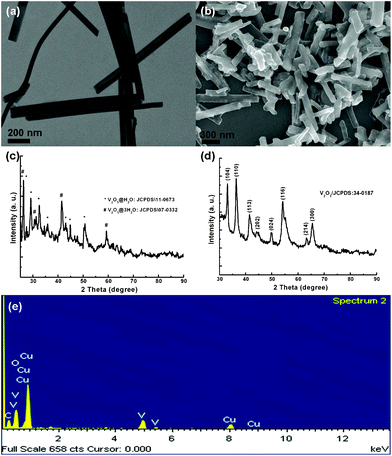 | ||
| Fig. 1 V2O5·xH2O nanobelts and V2O3@carbon nanocomposite are shown in (a) and (b), respectively. (c) and (d) show the corresponding XRD patterns. EDX elemental analysis for V2O3@carbon nanocomposite is presented in (e). | ||
In order to investigate the structural details, high-resolution transmission electron microscopy (HRTEM) was employed. As shown in Fig. 2a, some coaxial cable-like nanowires are visible. The core of these nanowires seems to have a mesoporous structure, while the outer layer appears as a dense phase under the electron beam irradiation. As presented in Fig. 2b and supplementary information,† crystal lattices are clearly detected in the core of the nanowires, while well-graphitized layers are coating these nanowires. In view of the synthesis strategy as well as the precursors used in this work, we can conclude that the obtained nanowires consist of encapsulated V2O3 coated with a carbon layer.13–15,17–19 The outer carbon layer derives from the glucose polymerization and subsequent carbonization during calcination at elevated temperature in the inert atmosphere, while the V2O3 nanostructures are formed by the reduction of V2O5 as described below:
| V2O5·xH2O → V2O5 + xH2O | (1) |
| V2O5 + C → V2O3 + CO2 | (2) |
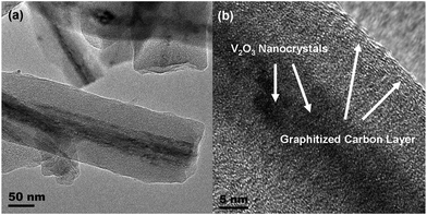 | ||
| Fig. 2 Low magnification TEM image (a) and high-resolution TEM image (b) reveal the structural details of V2O3@carbon nanocomposite. | ||
Raman spectroscopy (Fig. 3) is applied to determine the presence of the well-graphitized carbon layer and vanadium oxide. Until now, Raman data for V2O3 have scarcely been reported since this oxide is a poor light scatterer, especially when it is coated with carbon layers.20 The peaks ranging from 100 to 1000 cm−1 correspond to traces of V2O5 as reported previously;21 while the peaks at 1359.7 cm−1 (D band) and 1599.6 cm−1 (G band) are associated with disordered carbon and graphitic carbon atoms, respectively. The intensity of the G band is stronger than that of the D band, implying that the well-graphitized carbon dominates the carbon coating layer.14,22 As it is well known, the reductive capacity of carbon depends on the reaction temperature. Indeed, the reductive capacity is enhanced by increasing temperature. When the calcination temperature is increased from 700 to 800 °C, the encapsulated material is converted from V2O3 into a mixture of V2O3 and VO1.27, indicating a higher reduction degree induced by the carbon layer. In addition, the encapsulated vanadium oxide is damaged, forming nanoparticles as demonstrated in Fig. 4a. From Fig. 4a, it is clear that some nanoparticles are irregularly distributed inside of the carbon fibers and the corresponding XRD pattern shown in Fig. 4b indicates that the transformation from V2O3 to VO1.27 indeed takes place.
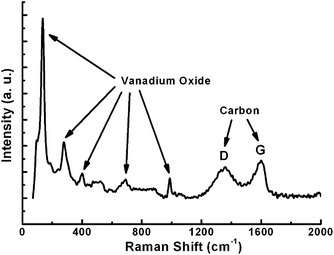 | ||
| Fig. 3 Raman spectrum of the nanocomposite, showing the presence of vanadium oxide and well-graphitized carbon layer. | ||
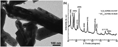 | ||
| Fig. 4 TEM image of the VOx@carbon nanocomposite obtained after high temperature calcination (800 °C) (a) and the corresponding XRD pattern (b), demonstrating the formation of VO1.27@carbon nanocomposite. | ||
Owing to the vaporization of water from the hydrated precursor, V2O5·xH2O (eqn (1)) and the oxygen removal from V2O5 by the carbon layer (eqn (2)), the formation of a mesoporous structure is reasonably expected. The nitrogen adsorption–desorption method (BET) was applied to determine the surface area and pore size characteristics of the samples obtained at 700 °C. As presented in Fig. 5, a specific surface area of 435.8 m2 g−1 is obtained by nitrogen adsorption–desorption profiles. The pore size is mainly distributed around 1.75 nm, which is highlighted in the inset of Fig. 5. The high surface area and pore size distribution suggest that the as-prepared sample will be exhibit good performance for electrolyte flooding and Li-ion insertion, being a potential promising candidate as an electrode material for Li-ion batteries (LIBs).
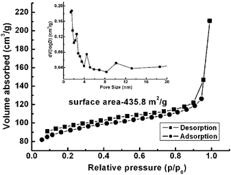 | ||
| Fig. 5 BET isotherm of the V2O3@carbon nanocomposite (a) and pore size distribution derived from the desorption branch (inset). | ||
The carbon coating technique is a well-developed and facile approach to form carbon@active nanocomposites using glucose as the carbon source.14,15,19 By precisely controlling the precursor dimensions and coating conditions, novel structures can be obtained, e.g., peapod-like Co@carbon and Co3O4@carbon nanocomposites.14 However, if the precursor size is too big or its physical properties limit the regular agglomeration due to a high melting point, only normal carbon-encapsulated composites will be achieved as presented in this work. This was also reported for other similar systems.13,15,17,18,23,24 The V2O5·xH2O precursor normally exists forming bundles. If they are used directly in carbon coating, the final product generally exhibits exposure of vanadium oxide species as shown in Fig. 6. This low-magnification scanning electron microscopy (SEM) image shown in Fig. 6a reveals a worm-like morphology for the sample calcined at 700 °C. Fig. 6b shows the magnified SEM image, unraveling the morphological details. It is clear that vanadium oxide species are entirely exposed outside, demonstrating the infeasibility of using bundle-like V2O5·xH2O as a precursor. Therefore, before carbon coating, strong ultrasonication of V2O5·xH2O nanobelt bundles is required.
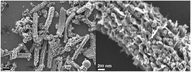 | ||
| Fig. 6 SEM images: low-magnification (a) and locally magnified (b) pictures, showing the influence of the precursors. When no strong ultrasonication is carried out on the V2O5·xH2O nanobelt bundles, no encapsulated V2O3@carbon nanocomposite will be formed after calcination. | ||
Vanadium sesquioxide (V2O3) is a multi-functional material frequently applied in conductive polymer composites and catalysis. Recently, it has been utilized in Li-based electrochemical energy storage systems as well as in both non-aqueous and aqueous systems as a cathode material.17,18 V2O3 possesses a high theoretical capacity of 1070 mAh g−1 as an anode material in LIBs, much higher than that of the currently commercialized carbon materials (380 mAh g−1). Besides, considering its abundance and low-toxicity, V2O3 may be a suitable anode material for practical applications in LIBs. However, one important issue that should be addressed is its low conductivity. Thus, conductive coatings or additives have to be incorporated into the systems in order to improve the conductivity of V2O3 since it is a pronounced Mott insulator, though a metal–insulator transition occurs at the critical temperature. Fig. 7 displays the electrochemical performance as an anode material for LIBs of the V2O3@carbon encapsulated structure. The ideal structure of the V2O3@carbon composites is an encapsulated mesoporous V2O3 nanostructure in well-graphitized carbon fiber since mesoporous V2O3 is able to be totally wetted by the electrolyte while the outer carbon layer can effectively prevent the collapse of V2O3 nanostructures and effectively conduct the electrons to the current collector, simultaneously. The one-dimensional (1D) architecture enables the interconnection of the composites, being surrounded by each other to form an efficient electrical network. Additionally, the interconnected architecture is a strengthened structure and will not be easily pulverized when lithiated and delithiated. Hence, the cyclic voltammetric profiles (CVs) remain almost unchanged even after 50 cycles as shown in Fig. 7a, clearly revealing the superior stability, greatly enhanced reversibility and cyclability of this novel encapsulated V2O3@carbon structure. Galvanostatic measurements were used for the first cycle of charge–discharge characterization and, as presented in Fig. 7b, a correlation between working potentials and specific capacities was established. The current densities are 500 mA g−1, 1 A g−1, 2 A g−1 and 5 A g−1 and the corresponding capacities are 670 mAh g−1, 540 mAh g−1, 330 mAh g−1, and 230 mAh g−1, respectively. The potential plateau initially drops from 1.2 V (vs. Li+/Li) and gradually decreases to 0.01 V (vs. Li+/Li), which is demonstrated by the CV profiles in Fig. 7a. The absence of a flat potential plateau related to a specific capacity implies that V2O3 reacts with Li ions smoothly and that several transition species exist until the completely reduced species, metallic vanadium, is formed. As the valence state of vanadium decreases, the potential is always decreasing, revealing the existence of a relationship between oxidation state and potential of vanadium oxides. Such a relationship was usually reported for other transition-metal oxides, where the conversion process dominates the Li storage mechanism.8–10 In order to investigate the reversibility and recoverability of V2O3@carbon nanocomposite from high-rate cycling, galvanostatic characterization was used (Fig. 7c). Initially, the capacity of the first cycle is above 900 mAh g−1. Such a high value during the first cycle is usually achieved using several anode materials, as previously reported for alloying and conversion process.9–11,13–15 In this case, irreversible reactions are believed to occur at the initial stage, e.g., decomposition of electrolyte. Then, a stable power delivery will be achieved during the following cycles. In Fig. 7c, it can be seen that a long-term specific capacity of 660 mAh g−1 is achieved after high-rate cycling, during which high current densities are employed step by step from 500 mA g−1 to 1 A g−1, 2 A g−1 and 5 A g−1, and then back to 500 mA g−1. The capacity retention is calculated to be above 98.5%, being an excellent value as compared to a large number of previous reports.25–28 In the meantime, the coulombic efficiency (CE) is normally no less than 93% when run for 250 cycles except for the first small number (supplementary information†).
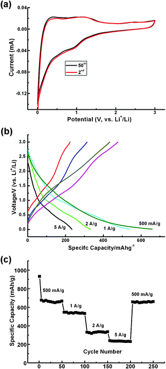 | ||
| Fig. 7 (a) CVs at the second and fiftieth cycles do not show significant differences, indicating the outstanding stability of the V2O3@carbon nanocomposite. (b) Galvanostatic measurements at various current densities indicate a correlation between working potentials (vs. Li+/Li) and specific capacities. (c) Cyclability demonstration: at least 98.5% specific capacity is retained after long-term experiments and high-rate cycling, further indicating the superior stability and cyclability of the V2O3@carbon nanocomposite. | ||
As already discussed, V2O3 is seldom used as an electrode material in LIBs, especially as an anode material.17,18 The reason might be its poor conductivity and metastability. In this work, an encapsulated structure of V2O3@carbon was successfully obtained by coating V2O5·xH2O nanobelts with layers of carbon species precursors and the subsequent calcination at high temperatures. In electrochemical systems, e.g., solar cells, fuel cells, supercapacitors and Li-ion batteries, there are common aspects that should be addressed in order to improve the electrochemical performance of these systems, e.g., rapid diffusion of the electrolyte into the electrode material, fast ionic exchange between the electrolyte and the electrode material, and efficient charge transfer from the electrode material to the current collector.5,8,29 For V2O3@carbon encapsulated nanocomposites, the mesoporous nature of the V2O3 nanostructures and the well-graphitized carbon layer coating these nanostructures exhibit major advantages over conventional systems. Thus, the three requirements can be achieved at the same time without the necessity of adding other ancillary additives, e.g., carbon black to enhance the physical properties of the system. Hence, the as-obtained V2O3@carbon encapsulated nanocomposite is a suitable and promising candidate for various applications in electrochemical systems such as Li-ion batteries and supercapacitors.
Conclusion
In summary, using a rational design, a novel functional nanocomposite consisting of mesoporous V2O3 nanostructures encapsulated inside well-graphitized carbon layers has been synthesized. The as-prepared nanocomposite exhibits an enhanced electrochemical performance as an anode material in Li-ion batteries, resulting from its unique structure. The improved rate capability, reversibility and cyclability make this composite structure a suitable and promising candidate as an anode material for LIBs and also a potential electrode material for supercapacitors. Besides the applications in electrochemical energy storage, this encapsulated nanocomposite might find important applications in other research fields such as catalysis and electronics on both fundamental and applied levels. More importantly, this contribution provides a general approach towards encapsulating active materials in carbon layers via hydrated precursors, being of great significance in the synthesis of nanocomposites.Experimental section
Materials
All chemicals or materials were used directly without any further purification. Ammonia metavanadate (Sigma-Aldrich, 99%), nitric acid (reagent grade, Sigma-Aldrich, 90%), titanium foil (0.127 mm (0.005 inch) thick, annealed, 99%, Alfa Aesar), D(+)-glucose (Cica-Reagent, Kanto Chemical), and lithium foil (99.9%, Charslton Technologies) were used in this work.Synthesis of V2O5·xH2O nanobelt bundles
Prior to the synthesis, a precursor solution was prepared. In general, 20 ml de-ionized water (DI water) was used to dissolve ammonia metavanadate (0.234 g) to form a bright yellow solution. Using nitric acid, the solution pH value was adjusted to 2. Then, another 15 ml DI water were added into the solution under vigorous stirring for 15 min. The prepared precursor solution was slowly poured into an autoclave. The autoclave was then tightly sealed and left in an oven at 200 °C for 16 h for the hydrothermal treatment. Once the reaction was completed, the precipitate was extracted and washed with pure ethanol, then dried in a conventional oven at 60 °C overnight.![[thin space (1/6-em)]](https://www.rsc.org/images/entities/char_2009.gif) :
:![[thin space (1/6-em)]](https://www.rsc.org/images/entities/char_2009.gif) 5 was prepared under strong magnetic stirring for at least 3 days. Then, a fraction of the active material was extracted and spread over Ti foils. Before and after spreading the samples, the Ti foils were weighed using a high-precision analytical balance (Sartorius, max weight 5100 mg, d = 0.001 mg). The difference was the mass of the spread samples on the Ti foils. The obtained pieces of Ti foils covered with the V2O3@carbon nanocomposite samples were then used as working electrodes with 1 M LiPF6 in ethylene carbonate and diethyl carbonate (EC–DEC, v/v = 1
5 was prepared under strong magnetic stirring for at least 3 days. Then, a fraction of the active material was extracted and spread over Ti foils. Before and after spreading the samples, the Ti foils were weighed using a high-precision analytical balance (Sartorius, max weight 5100 mg, d = 0.001 mg). The difference was the mass of the spread samples on the Ti foils. The obtained pieces of Ti foils covered with the V2O3@carbon nanocomposite samples were then used as working electrodes with 1 M LiPF6 in ethylene carbonate and diethyl carbonate (EC–DEC, v/v = 1![[thin space (1/6-em)]](https://www.rsc.org/images/entities/char_2009.gif) :
:![[thin space (1/6-em)]](https://www.rsc.org/images/entities/char_2009.gif) 1) as electrolyte. Celgard 2400 was used as the separator film to isolate both electrodes. Pure Li foil was used to serve as counter and reference electrodes. The cell was assembled in an Ar-filled glove box where moisture and oxygen concentrations were strictly limited to below 1 ppm. Galvanostatic cyclying measurements were performed using a Neware Battery Testing System (model 5 V1-5 mA) and the cyclic voltammetries (CV) were recorded using Autolab (model AUT71740) in a three-electrode cell.
1) as electrolyte. Celgard 2400 was used as the separator film to isolate both electrodes. Pure Li foil was used to serve as counter and reference electrodes. The cell was assembled in an Ar-filled glove box where moisture and oxygen concentrations were strictly limited to below 1 ppm. Galvanostatic cyclying measurements were performed using a Neware Battery Testing System (model 5 V1-5 mA) and the cyclic voltammetries (CV) were recorded using Autolab (model AUT71740) in a three-electrode cell.
Acknowledgements
Financial support from the Science and Engineering Research Council of A*STAR (Agency for Science, Technology and Research), Singapore, is gratefully acknowledged.References
- X. Q. Huang, S. H. Tang, X. L. Mu, Y. Dai, G. X. Chen, Z. Y. Zhou, F. X. Ruan, Z. L. Yang and N. F. Zheng, Nat. Nanotechnol., 2011, 6, 28 CrossRef CAS.
- Z. P. Huang, N. Geyer, P. Werner, J. D. Boor and U. Gösele, Adv. Mater., 2011, 23, 285 CrossRef CAS.
- D. W. Liu and G. Z. Cao, Energy Environ. Sci., 2010, 3, 1218 CAS.
- M. Winter and R. J. Brodd, Chem. Rev., 2004, 104, 4245 CrossRef CAS.
- Y. Wang, H. Xia, L. Lu and J. Y. Lin, ACS Nano, 2010, 4, 1425 CrossRef CAS.
- J. -M. Tarascon and M. Armand, Nature, 2001, 414, 359 CrossRef CAS.
- B. Kang and G. Ceder, Nature, 2009, 458, 190 CrossRef CAS.
- Y. Wang, H. J. Zhang, W. X. Lim, J. Y. Lin and C. C. Wong, J. Mater. Chem., 2011, 21, 2362 RSC.
- W. M. Zhang, J. S. Hu, Y. G. Guo, S. F. Zheng, L. S. Zhong, W. G. Song and L. J. Wan, Adv. Mater., 2008, 20, 1160 CrossRef CAS.
- Y. S. Hu, R. D. Cakan, M. M. Titirici, J. O. Müller, R. Schlögl, M. Antonietti and J. Maier, Angew. Chem., Int. Ed., 2008, 47, 1645 CrossRef CAS.
- S. B. Yang, X. L. Feng, S. Ivanovici and K. Müllen, Angew. Chem., Int. Ed., 2010, 49, 8408 CrossRef CAS.
- J. Yan, A. Sumboja, E. Khoo and P. S. Lee, Adv. Mater., 2011, 23, 746 CrossRef CAS.
- L. Y. Jiang, S. Xin, X. L. Wu, H. Li, Y. G. Guo and L. J. Wan, J. Mater. Chem., 2010, 20, 7565 RSC.
- Y. Wang, H. J. Zhang, L. Lu, L. P. Stubbs, C. C. Wong and J. Y. Lin, ACS Nano, 2010, 4, 4753 CrossRef CAS.
- P. Wu, N. Du, H. Zhang, J. X. Yu and D. R. Yang, J. Phys. Chem. C, 2011, 115, 3612 CAS.
- H. Li, P. Balaya and J. Maier, J. Electrochem. Soc., 2004, 151, A1878 CrossRef CAS.
- Y. Xu, L. Zheng, C. Z. Wu, F. Qi and Y. Xie, Chem.–Eur. J., 2011, 17, 384 CrossRef CAS.
- A. Odani, V. G. Pol, S. V. Pol, M. Koltypin, A. Gedanken and D. Aurbach, Adv. Mater., 2006, 18, 1431 CrossRef CAS.
- Y. Wang, C. Y. Foo, T. K. Hoo, M. Ng and J. Y. Lin, Chem.–Eur. J., 2010, 16, 3598 CrossRef CAS.
- C. Piccirillo, R. Binions and I. P. Parkin, Chem. Vap. Deposition, 2007, 13, 145 CrossRef CAS.
- V. G. Pol, S. V. Pol, J. M. Calderon-Moreno and A. Gedanken, J. Phys. Chem. C, 2009, 113, 10500 CAS.
- V. G. Pol, S. V. Pol, N. Perkas and A. Gedanken, J. Phys. Chem. C, 2007, 111, 134 CAS.
- P. M. Ajayan, O. Stephan, Ph. Redlich and C. Colliex, Nature, 1995, 375, 564 CrossRef CAS.
- M. Koltypin, V. Pol, A. Gedanden and D. Aurbach, J. Electrochem. Soc., 2007, 154, A605 CrossRef CAS.
- J. Liu, H. Xia, D. F. Xue and L. Lu, J. Am. Chem. Soc., 2009, 131, 12086 CrossRef CAS.
- H. X. Zhang, C. Feng, Y. C. Zhai, K. L. Jiang, Q. Q. Li and S. S. Fan, Adv. Mater., 2009, 21, 2299 CrossRef CAS.
- N. S. Choi, J. S. Kim, R. Z. Yin and S. S. Kim, Mater. Chem. Phys., 2009, 116, 603 CrossRef CAS.
- P. G. Bruce, B. Scrosati and J. M. Tarascon, Angew. Chem., Int. Ed., 2008, 47, 2930 CrossRef CAS.
- Y. Wang and G. Z. Cao, Adv. Mater., 2008, 20, 2251 CrossRef CAS.
Footnote |
| † Electronic supplementary information (ESI) available. See DOI: 10.1039/c2ra20472j |
| This journal is © The Royal Society of Chemistry 2012 |
