Drug–matrix interaction of sodium diclofenac incorporated into ureasil–poly(ethylene oxide) hybrid materials†
L.
Lopes
a,
E. F.
Molina
a,
L. A.
Chiavacci
b,
C. V.
Santilli
a,
V.
Briois
c and
S. H.
Pulcinelli
*a
aInstituto de Química, UNESP, PO Box 355, 14800-900, Araraquara, SP, Brazil
bFaculdade Ciências Farmacêuticas, UNESP, Araraquara, SP, Brazil
cSynchrotron SOLEIL, L'Orme des Merisiers, BP48, 91192, Gif-sur Yvette, France. E-mail: sandrap@iq.unesp.br; Fax: +55 16 33222308; Tel: +55 16 33019638
First published on 17th May 2012
Abstract
The objective of this work was to study the interactions between a model drug, sodium diclofenac (SDCF), and ureasil–poly(ethylene oxide) (PEO) hybrid materials, aiming to understand and to optimize the drug delivery behaviour. Ureasil–PEO hybrids obtained by the sol–gel process and containing short (PEO500) and long (PEO1900) polymer chains were prepared. Differential scanning calorimetry (DSC), Raman spectroscopy and 29Si NMR were used to investigate the interactions between SDCF and the hybrid matrix. The decrease in melting temperature of the semi-crystalline PEO1900 hybrid from 30.1 (SDCF-free matrix) to 22.3 °C (SDCF-loaded matrix) and the decrease of the Tg values of about −3 °C in SDCF-loaded PEO500 matrices associated to the Raman results confirm the interactions between SDCF and the PEO chains of the hybrid matrix. The role of the coexistence of crystalline and amorphous hybrid phase was clearly evinced by the bimodal drug release pattern achieved for the PEO1900 matrix.
1. Introduction
As is well known, drug–polymer interactions can significantly influence the physico-chemical properties and technological applications of solid dosage forms,1,2 determining their drug release properties.3,4 For instance, flurbiprofen could interact with hydroxypropyl cellulose by hydrogen bonding resulting in an increase in the drug release rate from the polymer matrix.5 In contrast, the interactions between Eudragit RS100 and three non-steroidal anti-inflamatory drugs (diflunisal, flurbiprofen, and piroxican) evinced that the drugs strongly interact with the ammonium groups present in the polymer chains decreasing their dissolution rate.6 Despite recognizing the importance of drug–polymer interactions, very little work has been done on drug–polymer blends and no study has attempted to relate the impact of drugs incorporation into organic–inorganic hybrid materials.7,8Organic–inorganic hybrid materials formed by ureasil cross-linked poly(ethylene oxide) (PEO) of variable length grafted at both ends to a siliceous backbone through urea cross links have been shown to simultaneously present acceptable transparency and mechanical flexibility, as well as to be very versatile as hosts for the inclusion of different inorganic species, including drug molecules. The hybrid molecular formula is shown in Scheme 1(a), n being the number of monomeric units of the PEO chain (n = 12 and 44 for PEO500 and PEO1900, respectively), in which the three possible interaction sites (silanol, urea and ether-type oxygen atoms) for the host of ionic or molecular species are indicated with arrows.9 This kind of hybrid material presents multifunctional characteristics and could be applied as a solid polymer electrolyte,10 in which the extraordinary ability of the PEO segments to dissolve guest salt species is combined with the chemical, mechanical and thermal stability of the siliceous network. More recently, these organic–inorganic hybrid hosts have also been used for the inclusion of anti-inflammatory and anticancer drugs showing their potential application as controlled drug delivery devices.11,12
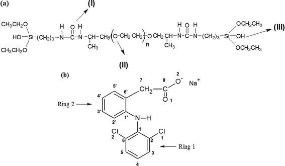 | ||
| Scheme 1 Chemical structural formulae for: (a) siloxane–PEO hybrids (n = 12 for PEO500 and 44 for PEO1900); (b) sodium diclofenac. | ||
The knowledge of the intermolecular interactions between the drug salt guest and the organic–inorganic hybrid host material is a pre-requisite for optimizing its use as a matrix for the controlled release of drugs. Sodium diclofenac, SDCF (Scheme 1(b)), is a powerful non-steroidal anti-inflammatory drug, used in the long-term treatment of inflammation and painful conditions of both rheumatic and non-rheumatic origin. SDCF has limited water solubility, especially in gastric juices and is unstable in aqueous solution.13 Such limited solubility in acidic media engenders problems in its oral bioavailability. Furthermore, its rapid elimination quantified by a half-life time of 1–2 h is a drawback for its formulation for controlled release devices.14 Hence the rapid absorption after oral administration justifies the need for development of sustained release devices. A possible method to overcome these limitations is the inclusion of SDCF in organic–inorganic hybrids materials.
In a recent work, some of us have demonstrated the possibility of obtaining transparent, rubbery, flexible, and water insoluble monolithic hybrid xerogels presenting controlled swellability and fine tunable drug-release kinetics from a simple sol–gel synthesis of a ureasil cross-linked PEO hybrid material.11 The drug delivery profiles have shown that the time taken to deliver the drug is higher than that observed for the swelling of the matrix. This fact can be related to the dissolution and diffusion time of the drug to leave the matrix or to the existence of drug–matrix interactions. Then, the optimization of the drug delivery behaviour requires a better knowledge of the drug–matrix interactions, so that the purpose of this work was to examine the interaction between SDCF and ureasil–PEO hybrids aiming to obtain information about the influence of these interactions on the drug delivery profiles. The drug–matrix interactions were evaluated by Differential Scanning Calorimetry (DSC), Raman, UV-Vis and 29Si NMR spectroscopies.
2. Experimental
Synthesis of the hybrid material
The ureasil cross-linking agent was covalently bonded to both ends of the macromer polyether15 by reacting the terminal aminopropyl groups of the functionalized PEO (O,O′-bis(2-aminopropyl)-poly(ethylene oxide)) with 3-(isocyanatopropyl)-triethoxysilane in a molar ratio of 1![[thin space (1/6-em)]](https://www.rsc.org/images/entities/char_2009.gif) :2. These commercially available reagents (Fluka, Aldrich) were stirred together in tetrahydrofuran (THF) under heating at 60 °C for 15 h. Then, the THF solvent was removed by evaporation at 60 °C, leading to the hybrid precursor (EtO)3Si(CH2)3NH(O
:2. These commercially available reagents (Fluka, Aldrich) were stirred together in tetrahydrofuran (THF) under heating at 60 °C for 15 h. Then, the THF solvent was removed by evaporation at 60 °C, leading to the hybrid precursor (EtO)3Si(CH2)3NH(O![[double bond, length as m-dash]](https://www.rsc.org/images/entities/char_e001.gif) C)NHCHCH3CH2–(polyether)–CH2CH3CHNH(OC)NH(CH2)3Si(OEt)3. This synthesis was adopted for PEO with 500 and 1900 g mol−1 average molecular weights, labeled hereafter PEO500 and PEO1900 hybrids. In the second step silanol moieties were generated, followed by condensation reactions to form ureasil cross-linking nodes. The hydrolysis of –(SiOCH2CH3)3 was initialized by adding 3 mL of a water/ethanol mixture (0.03 v/v) containing 110 mg kg−1 of HCl catalyst (oral toxicity limit 900 mg kg−1) to 1.5 g of precursor. In synthesis of 0.5% w/w drug loaded samples 75 mg of the sodium diclofenac (SDCF, 2-[(2,6-dichlorophenyl)amino]benzeneacetic acid sodium salt, (oral dietary human dosage: between 50–150 mg; oral lethal dosage (LD50): 53; 95 and 157 mg kg−1 for rats, mice and rabbits, respectively (Material Safety Data Sheet sodium diclofenac MSDS)) was dissolved in the HCl hydrolysis solution and added to the precursor. Finally, cylindrical monolithic xerogels of approximately 20 mm diameter and 2 mm height were obtained after drying under vacuum at 70 °C for 24 h.
C)NHCHCH3CH2–(polyether)–CH2CH3CHNH(OC)NH(CH2)3Si(OEt)3. This synthesis was adopted for PEO with 500 and 1900 g mol−1 average molecular weights, labeled hereafter PEO500 and PEO1900 hybrids. In the second step silanol moieties were generated, followed by condensation reactions to form ureasil cross-linking nodes. The hydrolysis of –(SiOCH2CH3)3 was initialized by adding 3 mL of a water/ethanol mixture (0.03 v/v) containing 110 mg kg−1 of HCl catalyst (oral toxicity limit 900 mg kg−1) to 1.5 g of precursor. In synthesis of 0.5% w/w drug loaded samples 75 mg of the sodium diclofenac (SDCF, 2-[(2,6-dichlorophenyl)amino]benzeneacetic acid sodium salt, (oral dietary human dosage: between 50–150 mg; oral lethal dosage (LD50): 53; 95 and 157 mg kg−1 for rats, mice and rabbits, respectively (Material Safety Data Sheet sodium diclofenac MSDS)) was dissolved in the HCl hydrolysis solution and added to the precursor. Finally, cylindrical monolithic xerogels of approximately 20 mm diameter and 2 mm height were obtained after drying under vacuum at 70 °C for 24 h.
Solid state 29Si MAS/NMR spectra were recorded using an INOVA 300 Varian spectrometer at the Larmor frequency of 59.59 MHz. Chemical shifts were quoted in ppm from a tetramethylsilane (TMS) reference. 29Si NMR spectra were analysed using iterative least-square curve-fitting procedure in the PeakFit software (Jandel Corporation, 2591 Rerner Boulevard © 1995, AISN Software). The best fit of the experimental data was obtained by employing the Voigt band shapes varying the frequency, bandwidth and the intensity of the peaks. The standard error of the curve-fitting procedure was less than 0.01.
Differential scanning calorimetry (DSC) measurements were obtained in a TA Instrument model Q100. Disk sections of approximately 20 mg, removed from the monolithic hybrid xerogels, were placed into 40 μL aluminium cans. Each sample was heated from −90 to 350 °C at 10 °C min−1. The purge gas used in all the experiments was high purity nitrogen supplied at a constant 75 cm3 min−1 flow rate.
Raman data were recorded using a RXN1-785 Raman spectrometer from Kaiser Optical Systems Inc. (KOSI) equipped with a near IR laser diode working at 785 nm as excitation light and with a CCD detector for providing simultaneous full spectral collection of Raman data from 100 to 3200 cm−1. The transmitted laser power at the sample position was about 75 mW. The acquired spectra are the result of 36 scans each with an integration time of 50 s and the spectral resolution was 2 cm−1.
In vitro drug release
For the monitoring of the evolution of the release process over time by UV-Vis spectroscopy, about 0.2 g of monolithic SDCF loaded hybrid was immersed in 100 mL deionized water heated at 37 °C and vigorously stirred. UV-Vis absorption data were recorded in the 190–300 nm wavelength range using a Varian Cary 50 dual beam spectrophotometer fitted with a fibre optic coupler equipped with a solarization-resistant immersion probe. A 2 mm solution thickness is analysed using the immersion probe, making the technique sensitive to the SDCF species delivered in water solution. The acquisition scan rate was 300 nm min−1, allowing the record of a full spectrum in 30 s every 60 s. Standard stock SDCF aqueous solutions, with different concentrations, were measured by UV-Vis and used to build up the calibration curve used to the quantitative determination of the cumulative SDCF release in water at 37 °C.3. Results and discussion
3.1. Drug incorporation and polycondensation of ureasil linkages
The 29Si MAS/NMR spectra of unloaded and SDCF-loaded samples prepared with both the high and the low molecular weight polymer PEO1900 and PEO500 are shown in Fig. 1(a) and 1(b), respectively. Irrespective of the PEO molecular weight and the presence of SDCF all the 29Si NMR spectra exhibit two signals around −58 and −66 ppm. Taking account for the conventional Tm silicon (Si) notation (m = 1, 2 and 3 represents the number of Si atoms bonded to O–Si units) in which the resonances T1, T2 and T3 are ascribed to (CH2Si(OSi)(OR)2), (CH2Si(OSi)2(OR)) and (CH2Si(SiO)3) sites, R = H or CH2CH3, respectively, the observed peaks were attributed to T2 and T3 resonances.16,17 The degree of polycondensation (PC) was calculated by integrating the area (%) under each Si species intensity peak and considering the PC value expected for the different Tm units, where PC values are 33.3%, 66.7%, and 100% for T1, T2, and T3, respectively. Accordingly, the degree of polycondensation is obtained using the following formula PC(%) = 1/3(T1 + 2T2 + 3T3)% in which Tm is the area of the corresponding NMR resonance. The relative population of the two 29Si environments (T2 and T3) and the PC values are gathered in Table 1. The higher PC observed for PEO500 is consistent with the lower nominal hydrolysis ratio (h = [H2O]/[Si]) achieved by addition of an equal volume of HCl solution in the synthesis of the PEO500 (h = 2.0) and PEO1900 (h = 4.6) hybrids. In fact, the addition of water in excess or in substoichiometric quantities determines the equilibrium between the hydrolysis polycondensation reactions, favouring, in the case of the PEO500 hybrid, water forming polycondensation and higher PC values. The dominance of the T3 environment suggests that under the experimental conditions used for the hybrid synthesis the condensation reactions favoured the growth of branched siloxane structures. Moreover, the high degree of polycondensation verified for all the samples suggests that only a few terminal OCH2CH3 or OH groups bonded to the Si atoms persist, limiting the possibility for SDCF to interact with the silanol groups of the matrix (Scheme 1(a)).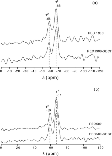
| Hybrid | T 2 (%) | T 3 (%) | PC (%) |
|---|---|---|---|
| PEO1900 | 44 | 56 | 85 |
| SDCF-PEO1900 | 32 | 68 | 89 |
| PEO500 | 29 | 71 | 90 |
| SDCF-PEO500 | 17 | 83 | 94 |
3.2. Drug–hybrid matrix interactions from thermal analysis
The DSC curves of the unloaded and SDCF-loaded PEO500 and PEO1900 matrices coupled to that of the SDCF salt are shown in Fig. 2. The DCS curve of the SDCF salt presents a sharp endothermic peak at 293.3 °C characteristic of the salt melting and an exothermic event in between 313 and 334 °C, associated to the drug molecule oxidation.18 The lack of these events in SDCF-loaded ureasil–PEO matrices proves the absence of undissolved crystalline salt. This good dissolution of the SDCF molecules in both hybrid matrices lead to the emergence of a broad endothermic peak centred around 247 °C. We attributed this event to the decomposition of a complex formed between the SDCF molecules and the hybrid matrix. For both the unloaded and the SDCF-loaded PEO matrices a broad endothermic peak centred around 130 °C was observed and attributed to the evaporation of water or ethanol molecules entrapped in the hybrid matrix. The presence of these residual polar molecules is associated to the hydrophilic character of the matrix.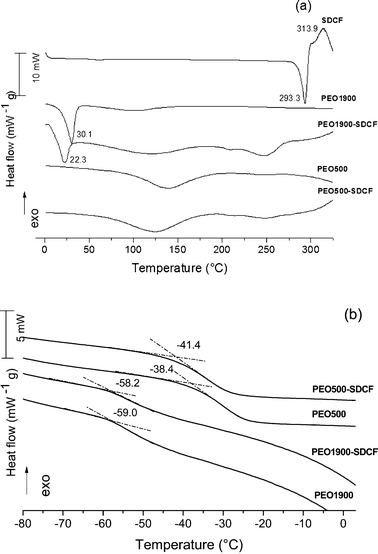 | ||
| Fig. 2 DSC curves of the SDCF salt compared to the unloaded and SDCF-loaded PEO500 and PEO1900 matrices. | ||
The DSC curves of the unloaded and SDCF-loaded PEO1900 hybrids revealed the presence of sharp endothermic peaks centered at 30.1 °C and 22.3 °C, respectively, corresponding to the melting of the crystalline PEO domains.19 As expected20 for the PEO molecular weight less than 1000 g mol−1, these melting peaks are not observed for both the unloaded and the SDCF-loaded PEO500. The reason for this is that the motion of the chains of PEO is partially disturbed by the cross-links, and when the molecular weight of PEO decreases below a critical value, the length of the chain of PEO is not long enough to fold and to crystallize. The crystallinity degree (CD) for the PEO1900 based samples was calculated taking account for the ratio21 between the observed fusion enthalpy variation, ΔHf, and the standard melting enthalpy for 100% crystalline PEO, ΔHp = 188.9 J g−1 (CD (%) = (ΔHf/ΔHp) × 100).22 The CD values calculated for the unloaded PEO1900 (29%) is higher than the one obtained for the SDCF-loaded PEO1900 (11%), evincing that the presence of SDCF partly hinders the natural crystallization tendency of PEO1900. Feldgitscher et al.23 explain that the inhibition of the crystallization of the PEO is induced by complexation of the ions with the polyether oxygen atoms. This difference in CD parameter for both matrices is used as additional proof for the immobilization of the ions at the amorphous PEO moieties. This feature along with the reduction of the fusion temperature under drug incorporation proves that the SDCF is miscible in the amorphous PEO phase, forming a liquid solution which partly hinders the crystallization of the PEO1900 hybrid.
Furthermore, the low temperature region of the DSC curves shows a relatively sharp change of heat capacity (ΔCp), characteristic of the glass transition (Fig. 2(b)). This single glass transition anomaly is evidence for the random distribution of drug molecules in the polymeric phase and thus explains the absence of microphase separation phenomena often reported for salt doped polyether,24i.e., the coexistence in the amorphous phase composed of drug rich PEO microdomains in equilibrium with drug free PEO regions. Moreover the Tg value changes from −59.0 to −58.2 °C and from −38.4 to −41.4 °C for the unloaded and the SDCF-loaded PEO1900 and PEO500, respectively. The significant decrease in the glass transition point upon drug incorporation into the PEO500 hybrid indicated that the SDCF molecules interact with the polymers as a plasticizer, confirming the formation of an amorphous solid solution with the organic polymers of the hybrid matrix. The slight increase in Tg upon drug loading on PEO1900 hybrid indicates that the chain mobility and interchain interactions of the amorphous polymer phase are less affected by SDCF incorporation. Accordingly, we concluded that in the case of the semi-crystalline ureasil–PEO hybrid the dissolution of SDCF in the amorphous phase hinders the crystallization of the polymeric moieties leading to a decrease of the CD value from 29% (unloaded) to 11% (loaded) PEO.
3.3. Drug–hybrid matrix interactions from Raman
In order to better understand the drug–hybrid matrix interaction, Raman spectroscopy was used to follow the changes of the SDCF molecules or of the ureasil–PEO characteristic vibration bands compared to those observed for the crystalline SDCF salt or for the unloaded matrices. Fig. 3 presents the Raman spectra of the SDCF salt, the unloaded and the SDCF-loaded PEO1900 and PEO500 matrices, in the spectral range between 200 and 1800 cm−1, showing the assignment of well-known main Raman bands of the SDCF molecule.25Fig. 3 revealed that only the regions of the spectrum localized between 200–480 cm−1 and 1500–1800 cm−1 do not present superimposition of bands characteristic of undoped PEO matrices and of the SDCF. For this reason the detailed analysis of the vibration bands was only performed in these spectral regions.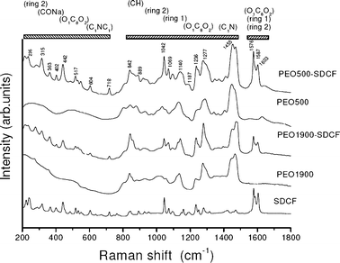 | ||
| Fig. 3 Raman spectra of the SDCF salt compared to the unloaded and the SDCF-loaded PEO1900 and PEO500 matrices. | ||
The full spectral collection of Raman data from 200–480 cm−1 is presented in Fig. 4 for the SDCF salt compared to the unloaded and the SDCF-loaded PEO500 (Fig. 4(a)) and PEO1900 (Fig. 4(b)) matrices. An important displacement of the peaks localized at 318, 367 and 402 cm−1, attributed to the C1–N–C1′, Cl–C and O1C8O2 vibrations respectively, is observed for the SDCF loaded hybrids in comparison to the salt.22 For the bands related to the C1–N–C1 and Cl–C vibrations, this displacement occurs from high to low wavenumbers, while for the band attributed to the O1C8O2 vibration the shift occurs from low to high wavenumbers, revealing that these changes are not due to a simple matrix effect. The carboxylate and the amine complexing sites of SDCF are not affected in a similar way when the molecule is embedded into the hybrid matrix, evincing that drug–matrix interactions preferentially involve the amine and carbonyl groups of the SDCF molecule.
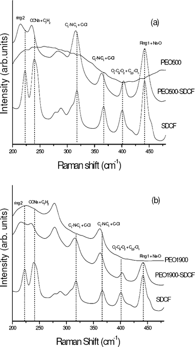 | ||
| Fig. 4 Raman spectra of SDCF salt compared to the unloaded and SDCF-loaded PEO500 (a) and PEO1900 (b) matrices in the 200–480 cm−1 spectral range. | ||
The broad structure characteristic of the spectral collection of Raman data from 1500–1800 cm−1 for the SDCF salt compared to the unloaded and the SDCF-loaded PEO500 (Fig. 5(a)) and PEO1900 (Fig. 5(b)) matrices could easily be deconvoluted into three Lorentzian bands localized around 1578, 1587 and 1605 cm−1 and attributed to the O1C8O2 asymmetric stretching vibration, and the dichlorophenyl and phenylacetate rings streching vibrations, respectively. These bands’ deconvolution as well as the parameters used for this data deconvolution are given in the ESI† (Fig. S1). The bands at 1577.6 and 1604.8 cm−1 in the Raman spectrum of the SDCF salt show a shift to 1576.5 and 1603.3 cm−1 in the SDCF-PEO500 and to 1576.3 and 1602.8 cm−1 in the SDCF-PEO1900 matrices. A broadening of these bands is also observed in these Raman spectra, as shown in Table 2. Similar shift and broadening of this set of bands has been observed by Iliescu et al. for a mixture of SDCF and β-cyclodextrin (βCD) and attributed to the existence of interactions between the phenylacetate group of the SDCF species and the βCD molecule.25,26
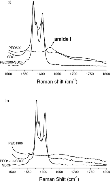 | ||
| Fig. 5 Raman spectra of the SDCF salt compared to the unloaded and SDCF-loaded PEO500 (a) and PEO1900 (b) matrices in the 1500–1800 cm−1 spectral range. | ||
| Peak position | FWHM (cm−1) | Vibrational assignment25,26 | |||||
|---|---|---|---|---|---|---|---|
| SDCF reference 25 and 26 | SDCF | SDCF–PEO500 | SDCF–PEO1900 | SDCF | SDCF–PEO500 | SDCF–PEO1900 | |
| 223 | 223.9 | 214.9 | 215.2 | — | — | — | Ring 2 |
| 239 | 240.2 | 234.9 | 235.2 | — | — | — | C–O–Na def + C7H2 |
| 318 | 318.1 | 316.2 | 315.6 | — | — | — | C1NC1′ def + C–Cl def |
| 367 | 366.7 | 363.5 | 362.3 | — | — | — | C1NC1′ def + C–Cl def |
| 402 | 401.2 | 404.1 | 403.0 | — | — | — | O1C8O2 def + Cl1C2;3 |
| 442 | 441.9 | 441.4 | 441.9 | — | — | — | Ring 2 + Na–O str |
| 1578 | 1577.6 | 1576.5 | 1576.3 | 7.1 | 9.4 | 8.8 | O1C8O2 as. str |
| 1585 | 1586.6 | 1587.1 | 1587.3 | 11.8 | 18.2 | 17.4 | Ring 1 + 2 str |
| 1605 | 1604.8 | 1603.3 | 1602.8 | 10.2 | 15.3 | 10.2 | Ring 1 + 2 str |
The observed change in the SDCF-loaded PEO matrices’ bandwidths indicates a decrease in the vibrational relaxation time of both the asymmetric stretching vibration of the COO− group and the phenylacetate ring,26 confirming the interaction between both the COO− group and the phenylacetate ring of SDCF molecule with the hybrid matrix. Otherwise, the significant broadening (FWHM = 7.1 cm−1) of the band localized at 1587cm−1, without position change is attributed to the modification of the chemical environment of the dichlorophenyl group of the SDCF molecule. It is noteworthy that the broadening of three bands is larger for the PEO500 matrix than for the PEO1900 one, suggesting that the drug interaction with the shortest polymeric chains is higher than with the longest. This behavior could be due to the interaction between the amine group bonded to the dichlorophenyl ring of the SDCF molecule and the urea groups or the ether-type oxygen atoms present in these hybrid matrices, promoting changes in the chemical environment of this ring. These observations are in good agreement with the shifts observed for the bands attributed to C1–N–C1′, Cl–C and O1C8O2 groups (Fig. 4).
Finally a close inspection of Fig. 5 in the region above 1600 cm−1 reveals that the position of the band related to the so-called amide I vibration mode of the urea site (site I in Scheme 1) of the polymeric chain shifts by about 20 cm−1 (1630 for 1650 cm−1) from the unloaded to the SDCF-loaded PEO500 matrix. This effect, already observed in similar matrices doped with NaClO4 anions, is ascribed to the disruption of the hydrogen bonded urea–PEO structure, initially present in the host matrix, caused by the interaction of the drug with the polymeric chain. This finding is consistent with the plasticizer effect revealed by the decrease of Tg for the PEO500 hybrid upon drug loading (Fig. 2(b)). The change observed for the position of the amide I band is more evident for the PEO500 hybrids, due to the higher proportion of urea groups present in PEO500, than for the PEO1900 hybrids.
3.4. Drug release profile
The increase of the SDCF concentration in the releasing medium as a function of the time of immersion in water was followed by monitoring the characteristic absorption band of the SDCF molecules at 276 nm. The release profiles of both the 5% w/w SDCF-loaded PEO500 and PEO1900 hybrids in water are shown in Fig. 6, while a typical evolution of the absorption band is shown in the insert of this figure. Irrespective from the molecular weight of the polymeric chain used in the hybrids’ synthesis the release profile shows fast SDCF liberation during the first four hours of water immersion. Following the experiment, the higher the PEO molecular weight of the hybrid matrix the higher the total quantity of SDCF released, so that after 5 h of the release essay 85% of the SDCF was released from PEO1900 hybrid, while just 70% was released from the PEO500 one. After that both the matrices reach an equilibrium state described by the plateau in Fig. 6. This difference in the final cumulative drug release is most likely due to the high proportion of urea groups present in the PEO500 hybrid (30%) with respect to PEO1900 hybrid (15%). This feature indicates that the interactions between the amine group bonded to the dichlorophenyl ring of the SDCF molecule and the urea groups present on the hybrid matrices revealed by Raman (Fig. 5) are enough intense to prevent the dissolution of these drug molecules in aqueous media. Moreover, the plasticizing role of SDCF, revealed by the decrease of Tg of the PEO500 hybrid upon 5% w/w loading, increases segmental motion of chains inducing a fast SDCF liberation. This explains the faster release of the 5% w/w loaded PEO500 hybrid as compared to the previously reported release profile of the 1% w/w loaded PEO500 matrix.11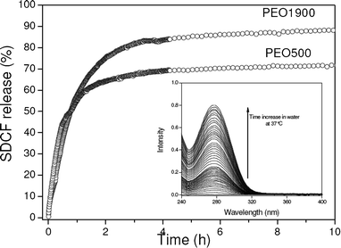 | ||
| Fig. 6 Cumulative percentage of initial SDCF loading released in water from PEO500 and PEO1900 matrices determined from the UV-Vis absorption of the release medium. A typical evolution of the absorption band of SDCF molecules at 276 nm is shown in the insert. | ||
The semi-empirical power law equation proposed by Peppas27 to characterize the different mechanism of drug release by diffusive transport through a monolithic polymeric matrix was applied to the experimental profiles shown in Fig. 6:
| Mt/M∞ = ktn | (1) |
The power low dependency predicted by eqn (1) is evinced by the linear trend of the release curves shown in the log–log plot of Fig. 7. A single straight line with a slope of 0.85 ± 0.03 describes the initial drug release profile (<40%) from the PEO500 hybrid matrix. The found value of n = 0.85 ± 0.03 indicates that the release seemed to be predominantly controlled by the water swelling rate. In the case of the PEO1900 matrix a bimodal pattern is revealed by the sharp bend in the curve that follows the two linear regions. The slopes of both the early and the late linear stages characterize n values of 0.52 ± 0.03 and 0.85 ± 0.03, respectively, suggesting that the predominant mechanism changes from Fickian diffusion to case II transport. Bimodal drug release profiles are generally achieved for heterogeneous devices like: multi-layer matrix tablets,29,30 samples showing different hydrophilic/hydrophobic balance,31 and the coexistence of crystalline and amorphous polymer domains.32 Accordingly, the bimodal release profile found for the PEO1900 matrix is most likely related to the semi-crystalline feature of the polymer composing the hybrid network. The Fickian diffusion control observed at the early stage indicates that the polymer crystals act as barriers to water absorption from the environment into the matrix. This is consistent with the low permeability of a thermodynamically compatible solvent into the crystalline PEO and the substantial higher diffusion of drug through the amorphous portion of the polymer.32 On the other side, the exponent n = 0.85 ± 0.03 achieved in the late stage indicates that the crystalline domains are transformed to an amorphous phase allowing the penetration of the hydrated swollen front, in agreement with the expected behavior for case II transport.
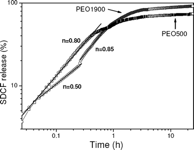 | ||
| Fig. 7 Log–log plot of release profiles of SDCF-loaded PEO500 and PEO1900 matrices during immersion in water at 37 °C. | ||
4 Conclusions
This study evinces that the incorporation of 5% w/w of SDCF into a ureasil–PEO hybrid matrix could be described as an amorphous solution in which a few types of drug–matrix interaction were revealed. The absence of a melting event, the plasticizing effect of the organic polymer framework, and the disruption of the hydrogen bonded urea–PEO structure demonstrate that the dominant interaction of the drug molecule in the amorphous solid solution formed with the PEO500 matrix. Raman data revealed that these drug–matrix interactions involve mainly the amine and carbonyl groups of the SDCF molecule through the formation of a new hydrogen bonding structure with urea groups present at the end of PEO chains. As a consequence of this drug–matrix hydrogen bonding the total amount of SDCF delivered decreases as the proportion of uresil linkages increases, i.e. by lowering the PEO chain length from PEO1900 to PEO500. Moreover, we also report here the possibility of changing the drug release profile from modal to bimodal by the partial crystallization of the hybrid matrix.Acknowledgements
This work has been financially supported by CAPES/COFECUB, CNPq, CNRS and FAPESP.References
- S. Y. Lin, C. L. Cheng and R. I. Perng, Eur. J. Pharm. Sci., 1994, 1, 313–322 CrossRef CAS.
- G. Hsiue, C. M. Liao and S. Y. Lin, Artif. Organs, 1998, 22, 651–656 CrossRef CAS.
- J. Huang, R. J. Wigent and J. B. Schwartz, J. Pharm. Sci., 2008, 97, 251–262 CrossRef CAS.
- C. S. Proikakis, P. A. Tarantili and A. G. Andreopoulos, Eur. Polym. J., 2006, 42, 3269–3276 CrossRef CAS.
- H. Yuasa and T. Suzuki, Chem. Pharm. Bull., 1994, 42, 354–358 CrossRef CAS.
- R. Pignatello, M. Ferro and G. Puglisi, AAPS PharmSciTech, 2002, 3, 35 CrossRef.
- N. A. Pepas, J. Z. Hilt, A. Khademhosseini and R. Langer, Adv. Mater., 2006, 18, 1345–1360 CrossRef.
- G. A. A. Soler Ilia, C. Sanchez, B. Lebeau and J. Patarin, Chem. Rev., 2002, 102, 4093–4138 CrossRef.
- J. A. Chaker, C. V. Santilli, S. H. Pulcinelli, K. Dahmouche, V. Briois and P. Judeinstein, J. Mater. Chem., 2007, 17, 744–757 RSC.
- S. C. Nunes, V. Z. Bermudez, D. Ostrovskii, P. C. Barbosa, M. M. Silva and M. J. Smith, Chem. Phys., 2008, 345, 32–40 CrossRef CAS.
- C. V. Santilli, L. A. Chiavacci, L. Lopes, S. H. Pulcinelli and A. G. Oliveira, Chem. Mater., 2009, 21, 463–467 CrossRef CAS.
- E. F. Molina, S. H. Pulcinelli, C. V. Santilli, S. Blanchandin and V. Briois, J. Phys. Chem. B, 2010, 114, 3461–3466 CrossRef CAS.
- B. P. Vilarnovo, L. J. Santana-Penin and J. J. Torres-Labandeira, Pharm. Sci., 1999, 9, 231–236 Search PubMed.
- P. Sipos, M. Szucs, A. Szabo, I. Eros and P. Szabo-Revesz, J. Pharm. Biomed. Anal., 2008, 46, 288–294 CrossRef CAS.
- K. Dahmouche, C. V. Santilli, S. H. Pulcinelli and A. F. Craievich, J. Phys. Chem. B, 1999, 103, 4937–4942 CrossRef CAS.
- S. S. Silva, R. A. S. Ferreira, L. Fu, L. D. Carlos, J. F. Mano, R. L. Reis and J. Rocha, J. Mater. Chem., 2005, 15, 3952–3961 RSC.
- M. C. Gonçalves, V. Z. Bermudez, R. A. S. Ferreira, L. D. Carlos, D. Ostrovskii and J. Rocha, Chem. Mater., 2004, 16, 2530–2543 CrossRef.
- F. Giordano, A. Rossi, I. Pasquali, R. Bettini, E. Frigo, A. Gazzaniga, M. E. Sangalli, V. Mileo and S. Catinella, J. Therm. Anal. Calorim., 2003, 73, 509–518 CrossRef CAS.
- M. Y. Hikosaka, S. H. Pulcinelli, C. V. Santilli, K. Dahmouche and A. F. Craievich, J. Non-Cryst. Solids, 2006, 352, 3705–3710 CrossRef CAS.
- C. Qiao, S. Jiang, D. Dong, X. Ji, L. An and B. Jiang, Macromol. Rapid Commun., 2004, 25, 659–663 CrossRef CAS.
- K. Y. Mya, K. P. Pramoda and C. B. He, Polymer, 2006, 47, 5035–5043 CrossRef CAS.
- V. P. R. Silva, G. G. Silva, V. Caliman, J. Rieumont, C. O. B. Miranda-Pinto, B. S. Archanjo and B. R. A. Neves, Eur. Polym. J., 2007, 43, 3283–3291 CrossRef CAS.
- C. Feldgitscher, H. Peterlik, M. Puchberger and G. Kickelbick, Chem. Mater., 2009, 21, 695–705 CrossRef CAS.
- C. Vachon, M. Vasco, M. Perrier and J. Prud'homme, Macromolecules, 1993, 26, 4023–4031 CrossRef CAS.
- T. Iliescu, M. Baia and V. Miclaus, Eur. J. Pharm. Sci., 2004, 22, 487–495 CrossRef CAS.
- T. Iliescu, M. Baia and W. Kiefer, Chem. Phys., 2004, 298, 167–174 CrossRef CAS.
- R. W. Korsmeyer, R. Gurny, E. Doelker, P. Buri and N. A. Peppas, Int. J. Pharm., 1983, 15, 25–35 CrossRef CAS.
- J. Siepmann and N. A. Peppas, Adv. Drug Delivery Rev., 2001, 48, 139–157 CrossRef CAS.
- X. Y. Xiong, K. C. Tam and L. H. Gan, J. Controlled Release, 2005, 103, 73–82 CrossRef CAS.
- A. Streubel, J. Siepmann, N.A. Peppas and R. Bodmeier, J. Controlled Release, 2000, 69, 455–468 CrossRef CAS.
- B. Jeong, Y. H. Bae and S. W. Kim, J. Controlled Release, 2000, 63, 155–163 CrossRef CAS.
- S. K. Mallapragada I and N. A. Peppas, J. Controlled Release, 1997, 45, 87–94 CrossRef.
Footnote |
| † Electronic supplementary information (ESI) available. See DOI: 10.1039/c2ra01216b |
| This journal is © The Royal Society of Chemistry 2012 |