Nano N-TiO2 mediated selective photocatalytic synthesis of quinaldines from nitrobenzenes†
Kaliyamoorthy
Selvam
and
Meenakshisundaram
Swaminathan
*
Department of Chemistry, Annamalai University, Annamalainagar 608 002, India. E-mail: chemres50@gmail.com; Fax: +91 4144 225072
First published on 9th February 2012
Abstract
N-Doped TiO2 using a new nitrogen precursor hydrazine hydrate was synthesized by a simple wet method. This photocatalyst was characterized by X-ray diffraction (XRD), Brunauer–Emmett–Teller (BET) surface area, high resolution transmission electron microscopy (HR-TEM), UV-Vis diffused reflectance spectra (DRS), photoluminescence (PL) and X-ray photoelectron spectroscopy (XPS). N-Doping does not change the phase of TiO2. It is found that the size of N-TiO2 is 15.6 nm with 134.72 m² g−1 surface area. XPS analysis reveals the presence of anionic nitrogen in TiO2 as O–Ti–N. Substitution of N in place of oxygen in the TiO2 lattice causes a decrease in oxygen vacancies which inhibits the recombination of electron–hole pairs. This catalyst was used for the selective one-pot synthesis of quinaldines from nitrobenzenes in ethanol under UV and visible light. N-TiO2 on irradiation induces a combined redox reaction with nitrobenzene and alcohol and this is followed by condensation-cyclization of aniline with oxidation products to give quinaldines. N-Doped TiO2 is found to be more efficient than metal doped TiO2 in quinaldine synthesis under visible light. Higher activity of the N-TiO2 could be attributed to its stronger absorbance of visible light.
1. Introduction
Nano-structured TiO2 materials have been studied extensively due to their high surface area and efficient electron–hole charge separation. Such materials hold great promise as efficient photocatalysts and for solar cells.1 Titanium dioxide (TiO2) has attracted elaborate interest because of its good photocatalytic activity, low cost and long-term stability. However, it can be activated only with UV light due to its large band gap of 3.2 eV. Present research is focussed on the development of doped photocatalysts for solar energy utilisation.2,3 Among the doped TiO2 catalysts, nitrogen-doped TiO2 plays a vital role in the field of solar photocatalysis.Many researchers have shown that doping nitrogen into TiO2 to form TiO2–xNx can efficiently shift the optical response to the visible spectral range.4–6 The synthesis of N-doped TiO2 nanophotocatalysts can be achieved by a sol–gel method,7 hydrothermal method,8 solvothermal method,9 chemical vapour deposition,10 emulsion precipitation,11 electrical oxidation,12 sputtering, ion implantation,13 spray pyrolysis5 and oxidation of TiN.6
Most of the above methods need a higher temperature or complicated and expensive equipment. Therefore, it is promising to develop a simple and lower temperature method for the preparation of the nitrogen-doped TiO2.
Li et al. reported the wet method for the synthesis of excellent visible-light responsive (from 400 to 550 nm) TiO2–xNx photocatalysts at low temperature.14 This catalyst was prepared by treating self-made amorphous TiO2 powder with hydrazine hydrate at 110 °C. On the other hand, the solution combustion technique (CS) has been extensively used for the synthesis of nanotitania [CS–TiO2].15–17 TiO2 obtained by the CS method is nanosized (8–12 nm) with high surface area. Therefore, nitrogen-doping on CS–TiO2 using hydrazine hydrate is expected to produce an efficient photocatalyst in UV and visible light. This nitrogen-doping method is very simple and does not need calcination at high temperature. However, N-TiO2 was mostly used for photodegradation of organic pollutants.18,19
Synthetic methods reported by Skraup, Doebner–Von Miller, Friedlander, and Combes have been developed for the preparation of quinolines.20–22 But many of these methods are not fully satisfactory with regard to operational simplicity, cost of the reagent and isolated yield. Photocatalytic synthesis of quinoline derivatives from nitrobenzene using TiO2, metal doped TiO2 and others had been reported earlier.23–25 In the present study, an attempt has been made for the preparation of N-doped TiO2 by a simple wet method using hydrazine hydrate with CS–TiO2. The efficiency of the N-TiO2 photocatalyst has been evaluated by the photocatalytic synthesis of quinaldines from nitrobenzenes.
2. Experimental
2.1. Materials and methods
All chemicals were of the highest purity available and were used as received. TiO2-P25 is a mixture of anatase and rutile (80![[thin space (1/6-em)]](https://www.rsc.org/images/entities/char_2009.gif) :20) supplied by Degussa, Germany. Nanosized titania (CS–TiO2) was prepared by the solution combustion synthesis method. This method involves the combustion of stoichiometric amounts of aqueous titanyl nitrate (obtained by the hydrolysis and subsequent nitration of the precursor compound titanium tetraisopropoxide) and fuel, glycine at 350 °C in a muffle furnace. A detailed description of the synthesis protocol is available elsewhere.15
:20) supplied by Degussa, Germany. Nanosized titania (CS–TiO2) was prepared by the solution combustion synthesis method. This method involves the combustion of stoichiometric amounts of aqueous titanyl nitrate (obtained by the hydrolysis and subsequent nitration of the precursor compound titanium tetraisopropoxide) and fuel, glycine at 350 °C in a muffle furnace. A detailed description of the synthesis protocol is available elsewhere.15
CS–TiO2 was dipped in hydrazine hydrate (80%) for 12 h, then filtered and dried at 110 °C for 3 h in air. Finally, the yellow nitrogen-doped TiO2 powder was formed. In the drying process, during evaporation, a glow was detected on the surface of the powder for a moment. Then the catalyst turned yellow.
2.2. Apparatus
X-Ray diffraction (XRD) patterns of catalysts were obtained using a Model D/Max 2550 V with Cu anticathode radiation. The diffractograms were recorded in a 2θ range between 10 and 80° in steps of 0.02° with a count time of 20 s at each point. The crystalline phase can be determined from integration intensities of anatase (101), rutile (110) and brookite (120) peaks and the average crystallite sizes were determined according to the Debye–Scherrer equation using the full width half maximum (FWHM) data of each phase.| D = Kλ/β cos θ |
Where D is the crystal size of the catalyst, λ is the X-ray wavelength (0.154 nm), β is the full width half maximum of the catalyst, K = 0.89 and θ is the diffraction angle.
The phase formation, particle size, surface morphology and crystallinity of pure and loaded catalysts were examined using transmission electron microscope (TEM) (Model JEOL TEM-3010) operated at 300 keV. The samples for TEM analysis were prepared by dispersing the catalysts in ethanol under sonication and depositing on a copper grid. High resolution TEM (HR-TEM) measurements were carried out using a JEOL-JEM-2010 UHR instrument operated at an acceleration voltage of 200 kV with a lattice image resolution of 0.14 nm. X-Ray photoelectron spectra (XPS) of the catalysts were recorded in an ESCA-3 Mark II spectrometer (VG Scientific Ltd., England) using Al Kα (1486.6 eV) radiation as the source. The spectra were referenced to the binding energy of C1s (285 eV).
The DRS of all the catalysts were recorded in a Shimadzu UV 2450 model UV-visible spectrophotometer in the range 800–190 nm equipped with an integrating sphere and using powdered BaSO4 as a reference.
The specific surface areas of the catalysts were determined using a Micromeritics ASAP 2020 sorption analyzer. The samples were degassed at 423 K for 12 h and analysis was performed at 77 K with N2 gas as the adsorbate. The Brunauer–Emmett–Teller (BET) multipoint method least-square fit provided the specific surface area.
Photoluminescence (PL) spectra at room temperature were recorded using a Perkin Elmer LS 55 fluorescence spectrometer. The nanoparticles were dispersed in carbon tetrachloride and excited using light of wavelength 300 nm.
2.3. Photocatalytic synthesis of quinaldines
In a typical experimental run, 50 mg N-TiO2 was suspended in 25 mL of an absolute ethanolic solution containing 25 mM of the nitrobenzene and irradiated by a 365 nm medium-pressure mercury lamp (Sankyo Denki, Japan; intensity I = 1.381 × 10⁻⁶ einstein L−1 s−1) after purging with N2 for 30 min. N2 bubbling (flow rate = 6.1 mL s−1) and magnetic stirring of the suspension were continued throughout the reaction while the temperature was maintained at 30 ± 1 °C. Progress of the reaction was monitored by TLC. Product analysis was performed by a Perkin-Elmer GC-9000 with a capillary column of DB-5 and flame ionization detector. GC-MS analysis was carried out using a Varian 2000 Thermo with the following features: capillary column VF5MS (5% phenyl-95% methylpolysiloxane), 30 m length, 0.25 mm internal diameter, 0.25 μm film thickness, temperature of column range from 50–280 °C (10 °C min−1) and injector temperature 250 °C, attached with mass spectrometer model SSQ 7000. The isolation was performed by column chromatography on a silica gel column by eluting with a co-solvent of hexane and ethyl acetate (volume ratio 8:2).
3. Results and discussion
3.1. XRD analysis
X-Ray diffraction (XRD) patterns of prepared TiO2 (bare TiO2), TiO2-P25 and N-TiO2 are shown in Fig. 1(a–c). The XRD patterns of bare TiO2 and N-TiO2 (Fig. 1a and 1c) are identical with the standard pattern of anatase (JCPDS: 01-078-2486C) and the rutile lines (01-089-0553C) are absent. The peaks at 25.43°, 37.92°, 48.03°, 53.97°, 55.05°, 62.70°, 68.80°, 70.39° and 75.05° are the diffractions of the (101), (004), (200), (105), (211), (204), (116), (200) and (215) crystal planes of anatase TiO2, respectively. This clearly reveals that the bare TiO2 and N-TiO2 are of the anatase phase. Fig. 1b displays the XRD pattern of TiO2-P25. Since it is a mixture of 80% anatase and 20% rutile, the XRD pattern shows both anatase and rutile lines. There is no diffraction peak of Ti–N compound in N-TiO2, which can be attributed to the small amount of the doped nitrogen. | ||
| Fig. 1 XRD patterns from (a) bare TiO2, (b) TiO2-P25 and (c) N-TiO2. | ||
3.2. UV-Visible diffuse reflectance spectra
The UV-Vis DRS absorption spectra of N-TiO2, bare TiO2 and TiO2-P25 are shown in Fig. 2. N-TiO2 has a higher absorption of visible light in the region 400–800 nm than bare TiO2. The band gap energy (Eg) of N-TiO2, determined using the equation Eg = 1239.8/λ, where λ is the wavelength of the absorption edge in the spectrum, is 2.96, which is less than Eg of bare TiO2 (3.18 eV). The band gap narrowing may be caused by introduction of nitrogen from hydrazine hydrate into the lattice of titanium. Thus, the sample of N-TiO2 showed excellent visible light absorption, indicating the increase of photocatalytic activity in the visible region. | ||
| Fig. 2 Diffuse reflectance spectra of (a) bare TiO2, (b) N-TiO2 and (c) TiO2-P25. | ||
3.3. Photoluminescence spectra of N-TiO2
Photoluminescence (PL) spectra of bare TiO2, N-TiO2 and TiO2-P25 are displayed in Fig. 3. TiO2 exhibited two photoluminescence emission peaks at 420 and 485 nm. Since PL emission is the result of the recombination of excited electrons and holes,26,27 the lower PL intensity of N-TiO2 indicates a lower recombination rate of excited electrons and holes (Fig. 3).28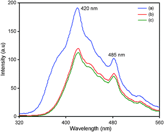 | ||
| Fig. 3 Photoluminescence spectra of (a) bare TiO2, (b) TiO2-P25 and (c) N-TiO2. | ||
3.4. HR-TEM analysis
High resolution transmission electron microscope images at two different regions are shown in Fig. 4a and 4b. It consists of intergrown fundamental particles with a rough and uneven surface. The intergrowth of small primary particles results in aggregates with significant extra framework void space, which is consistent with the textural mesoporosity observed in N2 adsorption isotherms, and it is due to the wormhole mesoporous structure. The selected area electron diffraction (SAED) pattern taken from these nanocrystalline particles (Fig. 4c) clearly reveals the presence of (101) plane concentric diffraction rings of anatase TiO2 phase. The high intense (101) feature highlighting the TiO2 crystallites is preferentially oriented along the (101) plane. The high-resolution lattice image shown in Fig. 4d confirms that the sample is composed of aggregates of crystalline titania nanoparticles with a d-spacing (interplanar spacing) of 0.35 nm, which corresponds to the (101) plane of anatase TiO2 phase (strongest intensity in SAED).29,30 Such high anatase crystallinity in the mesoporous TiO2 is highly desirable for photocatalysis. Fig. 4e shows the particle size distribution for N-TiO2. It can be seen that the N-TiO2 particle sizes are in the range from 5 to 35 nm. The distribution could be fitted well by a Gaussian function. The nanocrystallite size distribution of N-TiO2 samples is found to be a narrow one with an average particle size of 15.6 nm.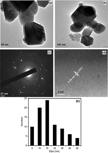 | ||
| Fig. 4 HR-TEM analysis: (a, b) images at two different regions of N-TiO2, (c) SAED pattern of N-TiO2, (d) lattice fringes of N-TiO2 and (e) particle size distribution of N-TiO2. | ||
3.5. XPS analysis
The chemical state of nitrogen in the catalyst has been analyzed through X-ray photoelectron spectra. The XPS survey spectrum of N-TiO2 sample in Fig. 5a shows the presence of the elements Ti, N and O for Ti2p, N1s and O1s core levels.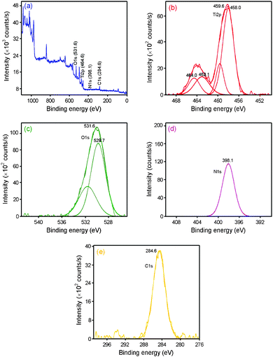 | ||
| Fig. 5 X-Ray photoelectron spectra of N-TiO2: (a) survey spectrum, (b) Ti2p peak, (c) O1s peak, (d) N1s peak and (e) C peak. | ||
N-TiO2 shows a single peak at 398.1 eV (Fig. 5d) for nitrogen N1s core level. Nitrogen from simple chemisorbed nitrogen or TiN should appear at ≤397.5 eV and nitrogen in NO or NO2 type species appear above 400 eV.31–33 Hence this N1s peak at 398.1 eV can be attributed to the anionic N in O–Ti–N linkages. Further the direct interaction between N and O in the lattice is ruled out as this interaction will increase the BE of the N1s level. It is also supported by the low BE of Ti2p of 458.1 eV compared to that of pure TiO2 (459.3 eV). From the above observations it can be concluded that the peak observed in the present study at 398.1eV is due to the N− anion incorporated in the TiO2 as a O–Ti–N structural feature.
Fig. 5b shows that the high intense peaks of Ti2p3/2 and Ti2p1/2 core levels of N-TiO2 appear at 458.1 and 463.1 eV, respectively. But with pure TiO2, binding energy peaks of Ti2p3/2 and Ti2p1/2 were reported at 459.3 and 465.0 eV, respectively.34 This reveals that nitrogen doping decreases binding energies of Ti2p3/2 and Ti2p1/2 peaks. Lower binding of Ti2p in N-TiO2 indicates the electronic interaction between Ti and N− anions, which can cause partial electron transformation from N to Ti. Electron density on Ti increases due to the lower electronegativity of nitrogen compared to oxygen. Earlier Miao et al. also assigned lower binding energy peaks to TiO2–xNx.35 This further confirms that nitrogen is incorporated into the lattice and substitutes for oxygen.
It can be seen from Fig. 5c that the O1s spectra of the N-doped TiO2 consisted of two peaks: one was centered at 529.7 eV and the other was centered at 531.6 eV, which is ascribed to nitrogen dopant. This indicates the presence of another type of oxygen due to the more covalent nature of N-TiO2. The carbon peak is attributed to the residual carbon from the sample and adventitious hydrocarbon from XPS instrument itself (Fig. 5e).
3.6. BET surface area analysis
In general, the surface area of the catalyst is the most important factor influencing the catalytic activity. N2 adsorption and desorption isotherms of bare N-TiO2 are shown in Fig. 6a. It can be seen from Fig. 6a, that the hysteresis loop in this material is of type IV and can be attributed to the mesoporous nature of the N-TiO2. The pore size distribution has been studied using B.J.H. method and is shown in Fig. 6b. The specific surface area and pore volume of bare N-TiO2 sample are 134.7 m2 g−1 and 0.99–0.13 cm³ g−1, respectively. It can be stated that the maximum pore volume is contributed by the pores with an average size of 21 Å. The bare TiO2 has a specific surface area of 74 m2 g−1. | ||
| Fig. 6 (a) N2 adsorption–desorption isotherms of N-TiO2 and (b) its pore size distribution. | ||
3.7. Photocatalytic synthesis of quinaldine from nitrobenzene with N-TiO2
Initial experiments were carried out with ethanolic solution of nitrobenzene containing TiO2 nanoparticles under different conditions. Irradiation of nitrobenzene and TiO2 in ethanol with 365 nm UV light produced cyclized product of quinaldine. Either the irradiation of ethanolic solution of nitrobenzene alone or the solution of nitrobenzene and the catalyst without light did not give any product. This indicates that both light and TiO2 are essential for the formation of quinaldine. The catalytic activities of N-TiO2 and TiO2-P25 for the synthesis of quinaldine were investigated for the reaction of nitrobenzene with ethanol.The changes in the concentrations of nitrobenzene, aniline and quinaldine during the photocatalytic reaction with TiO2, TiO2-P25 and N-TiO2 were determined at different times (Fig. 7). With TiO2-P25 and bare TiO2 (Fig. 7a and 7b), 6 h photoirradiation of nitrobenzene gave only 55 and 60% yield of the product quinaldine, respectively. In contrast, 70% yield of quinaldine was obtained in 5 h with N-TiO2 (Fig. 7c). This indicates that N-TiO2 promotes rapid and selective quinaldine production. Based on the results, it is obvious that N-TiO2 has higher photocatalytic activity compared with pure TiO2, which is ascribed to the N dopant. This is consistent with the analytical results. According to the XRD analysis, the N dopant of TiO2 decreased the crystalline size of TiO2 which resulted in the increase of surface area of the TiO2 from 74 to 134.0 m² g−1. N2 adsorption–desorption isotherms indicate the mesoporous nature of N-TiO2. Higher surface area and mesoporous structure increase the photocatalytic activity of N-TiO2. Furthermore the entry of N into the TiO2 lattice suppressed the particle growth and consequently caused a decrease of oxygen vacancies, which minimized the electron–hole recombination during the photocatalytic synthesis of quinaldines.
![Time-dependent change in the concentrations of nitrobenzene and products during photoirradiation of nitrobenzene with (a) TiO2, (b) TiO2-P25 and (c) N-TiO2. [Nitrobenzene] = 25 mM, N2 flow rate = 6.1 mL s−1, I = 1.381 × 10⁻⁶ einstein L−1 s−1, irradiation time = 5/6 h.](/image/article/2012/RA/c2ra01178f/c2ra01178f-f7.gif) | ||
| Fig. 7 Time-dependent change in the concentrations of nitrobenzene and products during photoirradiation of nitrobenzene with (a) TiO2, (b) TiO2-P25 and (c) N-TiO2. [Nitrobenzene] = 25 mM, N2 flow rate = 6.1 mL s−1, I = 1.381 × 10⁻⁶ einstein L−1 s−1, irradiation time = 5/6 h. | ||
GC-MS chromatograms recorded at different reaction times of the photocatalytic conversion of nitrobenzene in ethanol are presented in Fig. 8. GC-MS chromatograms reveal the formation of nitrosobenzene, aniline, N-hydroxyaniline, N-(propan-2-yl)aniline, 2-methyl-1,2,3,4-tetrahydroquinolin-4-yl(phenyl)amine during the quinaldine formation. The formation of byproducts, aniline and 2-methyl-1,2,3,4-tetrahydroquinoline after 6 h is also indicated by the GC-MS chromatogram. Very recently, we reported a similar reaction with a plausible reaction mechanism of the formation of quinaldine from nitrobenzene catalyzed by Au–TiO2.25 Since the intermediates formed are same, this reaction also follows the same mechanism. To find out the optimum conditions for maximum efficiency of this reaction, various experiments under different conditions were carried out.
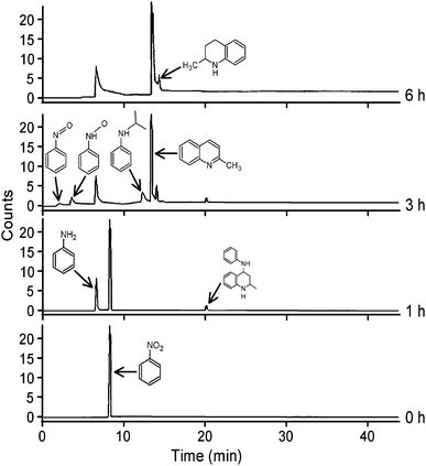 | ||
| Fig. 8 GC-MS chromatograms at different reaction times for the photocatalytic conversion of nitrobenzene with N-TiO2. | ||
3.8. Influence of the amount of catalyst
Keeping all other factors constant, we investigated the influence of the amount of N-TiO2 on the photocatalytic cyclization of quinaldine. For the same concentration of nitrobenzene, the amount of N-TiO2 was varied from 25 to 150 mg in 25 mL. Percentage of product formation increased with increasing amount of N-TiO2 up to 50 mg/25 mL (Fig. 9). Exceeding 50 mg, all incident photons might be scattered by catalyst particles. Therefore, in all studies, the optimum concentration of N-TiO2 for the photocatalytic oxidation has been fixed as 50 mg in 25 mL.![Percentage of quinaldine formed under different catalyst dosage. [Nitrobenzene] = 25 mM, N2 flow rate = 6.1 mL s−1, I = 1.381 × 10⁻⁶ einstein L−1 s−1, irradiation time = 5 h.](/image/article/2012/RA/c2ra01178f/c2ra01178f-f9.gif) | ||
| Fig. 9 Percentage of quinaldine formed under different catalyst dosage. [Nitrobenzene] = 25 mM, N2 flow rate = 6.1 mL s−1, I = 1.381 × 10⁻⁶ einstein L−1 s−1, irradiation time = 5 h. | ||
3.9. Influence of the substrate concentration
In another set of experimental runs, the influence of the initial concentration of nitrobenzene (15–45 mmol L−1) on the percentage conversion of quinaldine formation was investigated and the results are given in Table 1. It becomes obvious that the reaction rate decreases with increasing initial NB concentration. When 15 mmol L−1 NB was used 78% conversion was achieved within 5 h of UV irradiation, while only 37% conversion occurred in the case of 45 mmol L−1.| Run | Concentration of nitrobenzene (mM) | % of quinaldine |
|---|---|---|
| a Catalyst suspended = 50 mg/25 mL, N2 flow rate = 6.1 mL s−1, I = 1.381 × 10⁻⁶ einstein L−1 s−1, irradiation time = 5h. | ||
| 1 | 15 | 78 |
| 2 | 25 | 70 |
| 3 | 35 | 56 |
| 4 | 45 | 37 |
3.10. Effect of substituents
To demonstrate the generality and scope of this method, we examined this reaction with different nitroarenes in ethanol using N-TiO2 catalyst under UV light and the results are summarized in Table 2. This process is tolerant for the synthesis of various substituted quinaldines. Photoirradiation of alcohol solutions of different nitroarenes with N-TiO2 catalyst successfully afforded the corresponding quinaldines. 3-Nitrotoluene and 4-nitrotoluene gave 2,7-dimethylquinoline (80%) and 2,6-dimethylquinoline (75%), respectively. The quinaldine yield for 3-nitrotoluene is higher than for 4-nitrotoluene. In the synthesis of quinaldine, reduction of nitro group is followed by condensation with aldehyde and cyclization.| Reactant | Products yield (%) | Byproduct (%) | Conversion |
|---|---|---|---|
| a All reactions were performed with a 25 mM alcoholic solution of a reactant 50 mg of N-TiO2 suspension, I = 1.381 × 10⁻⁶ einstein L−1 s−1, irradiation time = 5 h. | |||
| Nitrobenzene | Quinaldine (70) | 29 | 99 |
| 3-Nitrotoluene | 2,7-Dimethylquinoline (80) | 18 | 98 |
| 4-Nitrotoluene | 2,6-Dimethylquinoline (75) | 23 | 98 |
| 4-Methoxy-nitrobenzene | 6-Methoxy-2-methylquinoline (70) | 26 | 96 |
| 3-Methoxy-nitrobenzene | 7-Methoxy-2-methylquinoline (72) | 22 | 94 |
| 3,5-Dimethyl-nitrobenzene | 2,5,7-Trimethylquinoline (66) | 19 | 85 |
| 4-Chloro-nitrobenzene | 6-Chloro-2-methylquinoline (36) | 64 | 99 |
| 4-Fluoro- nitrobenzene | 6-Fluoro-2-methylquinoline (20) | 79 | 99 |
It seems that the electron releasing group at the para position inhibits the condensation of the amino group with aldehyde. This is also revealed by 70% quinaldine formation by 4-methoxynitrobenzene which has a strong electron releasing group at the p-position. In the case of 3,5-dimethylnitrobenzene, the cyclization reaction is hindered due to the steric effect and this decreases the product yield (66%) when compared to 3-nitrotoluene (80%). In the case of 4-chloro- and 4-fluoronitrobenzenes, the yield of quinaldines was very low. This is attributed to photoinduced dehalogenation. Dehalogenated anilines have been identified in the GC-MS analysis.
Earlier it was reported that the irradiation of nitrobenzene (2 mmol) and TiO2 (0.5 g) in nitrogen saturated ethanol solution for 8–12 h gave ethoxy-tetrahydroquinolines as the major product.23 We obtained a different product with continues purging of nitrogen during the reaction. Our results reveal that of N-TiO2 has good oxidizing power under these experimental conditions.
3.11. Effect of additives
It was reported that additives such as KI, NaI could improve the reduction of nitrophenol. Hence, we tested the effect of the additives in the synthesis of quinaldines from nitrobenzene and the results are given in Table 3. It is found that the addition of KI and NaI increases the product yield. As the initial reaction in the quinaldine synthesis is the reduction of nitrobenzene, a similar trend reported for the reduction of nitrophenol is observed.16| Run | Additives | % of quinaldine |
|---|---|---|
| a [Nitrobenzene] = 25 mM, catalyst suspended = 50 mg/25 mL, N2 flow rate = 6.1 mL s−1, I = 1.381 × 10⁻⁶ einstein L−1 s−1, irradiation time = 5 h. | ||
| 1 | Without additive | 70 |
| 2 | KI | 76 |
| 3 | KBr | 71 |
| 4 | NaI | 84 |
| 5 | NaBr | 59 |
| 6 | Na2SO4 | 36 |
| 7 | C6H7SO3Na | 66 |
Increase in product yield is due to the hole scavenging effect of the iodide ion. The iodide ion was oxidized to iodine by holes generated by the irradiation of N-TiO2. Consequently the decrease in oxidation by holes will increase the reduction of nitrobenzene (Scheme 1).
 | ||
| Scheme 1 Mechanism for iodide participating in photocatalytic conversion of nitrobenzene to quinaldine. | ||
3.12. Photoredox cyclization in visible light
Since the synthesized N-TiO2 photocatalyst has a higher absorption in the visible region, we have investigated the photocatalytic activity of this catalyst under visible light (300 W tungsten lamp illumination) on the synthesis of quinaldine from nitrobenzene and the results are shown in Table 4. We have compared the photocatalytic performance of other metal doped photocatalysts such as Ag–TiO2, Pt–TiO2 and Au–TiO2 in this reaction using UV and visible light under the same experimental conditions.| Run | Catalyst | UV light (%) | Visible light (%) |
|---|---|---|---|
| a All reactions were performed with a 25 mM alcoholic solution of reactant, 50 mg of catalyst, N2 flow rate = 6.1 mL s−1, 300 W Tungsten lamp illumination, irradiation time = 5 h. | |||
| 1 | Prepared TiO2 | 60 | 16 |
| 2 | Ag–TiO2 | 65 | 45 |
| 3 | Au–TiO2 | 75 | 51 |
| 4 | Pt–TiO2 | 70 | 56 |
| 5 | N-TiO2 | 70 | 62 |
No product was obtained without the catalyst under visible light (>400 nm) after 5 h, while the yield of quinaldine from nitrobenzene was 16% with bare TiO2 in 5 h. The results reveal that N-TiO2 shows the best catalytic activity among the five catalysts under visible light. Order of activity of the catalysts for the synthesis of quinaldine from nitrobenzene using visible light is N-TiO2 > Pt–TiO2 > Au–TiO2 > Ag–TiO2 > bare TiO2.
All doped catalysts are more efficient than bare TiO2. The highest efficiency of N-TiO2 is due to its increased visible light absorption when compared to other doped catalysts.
4. Conclusions
N-TiO2 enables efficient quinaldine production from nitroarenes through a combined photoredox reaction. This process has following advantages when compared to other methods: (i) a cheap and stable reactant (alcohol), (ii) it does not require the use of acids, oxidants or reductants and (iii) the reaction proceeds under mild ambient conditions. N-TiO2 is more efficient than other metal doped catalysts in quinaldine synthesis under visible light. Therefore, this process has the potential to enable a more sustainable quinaldine synthesis from nitrobenzenes in UV and visible light. The combination of a photocatalytic redox-cyclization reaction presented here may help to develop a new strategy towards photocatalysis based organic synthesis.References
- D. V. Bavykin, J. M. Friedrich and F. C. Walsh, Adv. Mater., 2006, 18, 2807 CrossRef CAS.
- R. Asahi, T. Morikawa, T. Ohwaki, K. Aoki and Y. Taga, Science, 2001, 293, 269 CrossRef CAS.
- T. Murase, H. Irie and K. Hashimoto, J. Phys. Chem. B, 2004, 108, 15803 CrossRef CAS.
- S. Chen, P. Zhang, W. Zhu and D. Zhuang, Chin. J. Catal., 2004, 25, 515 CAS.
- O. Diwald, T. L. Thompson, E. G. Goralski, S. D. Walck and J. T. Yates, J. Phys. Chem. B, 2004, 108, 52 CrossRef CAS.
- S. Yin, H. Yamaki, M. Komatsu, Q. W. Zhang, J. S. Wang, Q. Tang, F. Saito and T. J. Sato, Solid State Sci., 2005, 7, 1479 CrossRef CAS.
- L. M. S. Colpini, H. J. Alves, O. A. A. dos Santos and C. M. M. Costa, Dyes Pigm., 2008, 76, 525 CrossRef CAS.
- M. C. Hidalgo, M. Aguilar, M. Maicu, J. A. Navio and G. Colon, Catal. Today, 2007, 129, 50 CrossRef CAS.
- Y. J. Kim, S. Y. Chai and W. I. Lee, Langmuir, 2007, 23, 9567 CrossRef CAS.
- S. Seifried, M. Winterer and H. Hahn, Chem. Vap. Deposition, 2000, 6, 239 CrossRef CAS.
- C. S. Hsieh, H. Zhu, T. Y. Wei, Z. J. Chung, W. D. Yang and Y. H. Ling, J. Eur. Ceram. Soc., 2008, 28, 1177 CrossRef CAS.
- Z. H. Zhang, Y. Yuan and G. Y. Shi, Environ. Sci. Technol., 2007, 41, 6259 CrossRef CAS.
- S. Chen, P. Zhang, W. Zhu and D. Zhuang, Chin. J. Catal., 2004, 25, 515 CAS.
- D. Li, H. Huang, X. Chen, Z. Chen, W. Li, D. Ye and X. Fu, J. Solid State Chem., 2007, 180, 2630 CrossRef CAS.
- G. Sivalingam, K. Nagaveni, G. Madras and M. S. Hegde, Ind. Eng. Chem. Res., 2002, 42, 687 CrossRef.
- G. Sivalingam, K. Nagaveni, M. S. Hegde and G. Madras, Appl. Catal., B, 2003, 45, 23 CrossRef CAS.
- G. Sivalingam, M. H. Priya and G. Madras, Appl. Catal., B, 2004, 51, 67 CrossRef CAS.
- J. Zhang, Y. Wu, M. Xing, S. A. K. Leghari and S. Sajjad, Energy Environ. Sci., 2010, 3, 715 CAS.
- H. Wang, J. Yan, W. Changm and Z. Zhang, Catal. Commun., 2009, 10, 989 CrossRef CAS.
- H. Skraup, Chem. Ber., 1880, 13, 2086 Search PubMed.
- O. Doebner and W. Miller, Bericht., 1883, 16, 2464 CrossRef.
- P. Friedlander, Ber. Dtsch. Chem. Ges., 1882, 15, 2572 CrossRef.
- K. H. Park, H. S. Joo, K. Ahn and K. Jun, Tetrahedron Lett., 1995, 36, 5943 CrossRef CAS.
- A. Hakki, R. Dillert and D. Bahnemann, Catal. Today, 2009, 144, 154 CrossRef CAS.
- K. Selvam and M. Swaminathan, Catal. Commun., 2011, 12, 389 CrossRef CAS.
- D. Li, H. Haneda, S. Hishita and N. Ohashi, Chem. Mater., 2005, 17, 2596 CrossRef CAS.
- J. Zhang, Y. Hu, M. Matsuoka, H. Yamashita, M. Minagawa, H. Hidaka and M. Anpo, J. Phys. Chem. B, 2001, 105, 8395 CrossRef CAS.
- H. Tang, K. Prasad, R. Sanjines, P. E. Schmidd and F. Levy, J. Appl. Phys., 1994, 75, 2042 CrossRef CAS.
- D. G. Kulkarni, A. V. Murugan, A. K. Viswanath and C. S. Gopinath, J. Nanosci. Nanotechnol., 2009, 9, 371 CrossRef CAS.
- H. Li, Z. Bian, J. Zhu, D. Zhang, G. Li, Y. Hou, H. Li and Y. Lu, J. Am. Chem. Soc., 2007, 129, 8406 CrossRef CAS.
- S. Sugai, H. Watanabe, T. Kioka, H. Miki and K. Kawasaki, Surf. Sci., 1991, 259, 109 CrossRef CAS.
- D. R. Rainer, S. M. Vesecky, M. Koranne, W. S. Oh and D. W. Goodman, J. Catal., 1997, 167, 234 CrossRef CAS.
- J. A. Rodriguez, T. Lindgren, J. Lu, C. G. Granquist and S. E. Lindquist, J. Phys. Chem. B, 2000, 104, 319 CrossRef CAS.
- M. Xing, J. Zhang and F. Chen, Appl. Catal. B, 2007, 89, 563 CrossRef.
- L. Miao, S. Tanemura, H. Watanabe, Y. Mori, K. Kaneko and S. Toh, J. Cryst. Growth, 2004, 260, 118 CrossRef CAS.
Footnote |
| † Electronic Supplementary Information (ESI) available: See DOI: 10.1039/c2ra01178f/ |
| This journal is © The Royal Society of Chemistry 2012 |