Stabilization of poly-iodides: structural influences of the cationic disulfides of 2-mercapto-3,4,5,6-tetrahydro-pyrimidine and 2-mercatpo-pyrimidine†
Anita M.
Owczarzak
ab,
Maciej
Kubicki
*b,
Nikolaos
Kourkoumelis
c and
Sotiris K.
Hadjikakou
*a
aSection of Inorganic and Analytical Chemistry, Department of Chemistry, University of Ioannina, 45110, Ioannina, Greece. E-mail: shadjika@uoi.gr; Fax: xx30-26510-08786; Tel: xx30-26510-08374
bDepartment of Chemistry, A. Mickiewicz, University, ul. Grunwaldzka 6, 60-780, Poznan, Poland. E-mail: mkubicki@amu.edu.pl
cSection of Inorganic and Analytical Chemistry, Department of Chemistry, University of Ioannina, 45110, Ioannina, Greece
First published on 6th January 2012
Abstract
The reaction of 2-mercapto-3,4,5,6-tetrahydro-pyrimidine (tHPMT) or 2-mercaptopyrimidine (PMTH) with hydroiodic or hydrochloric acids in the presence or absence of di-iodine in dichloromethane solutions resulted in the formation of complexes with formulae [2{(tHPMT)22+} 2(I−) (I42−)] (1), [2{(tHPMT)22+} Cl− 3(I3−)] (2), [6{(tHPMT)22+} 3(Cl−) 2(I−) 5(I3−)] (3) and [2{(PMTH2)+} I42−] (4). The compounds were characterized by FT-IR, and Raman spectroscopic techniques. The crystal structures of 1–4 were also determined by X-ray diffraction. Complexes 1 and 4 contain tetra-iodides di-anions (I42−) as counter parts. The linear geometry of tetra-iodides species is broken in case of 1 and the deviation from the linearity for this di-anion is greater than in any such molecule described thus far. Moreover in complex 3 with a hexa-iodide di-anion, (I62−) is detected by considering the distance of 3.67 Å as a bonding interaction.
Introduction
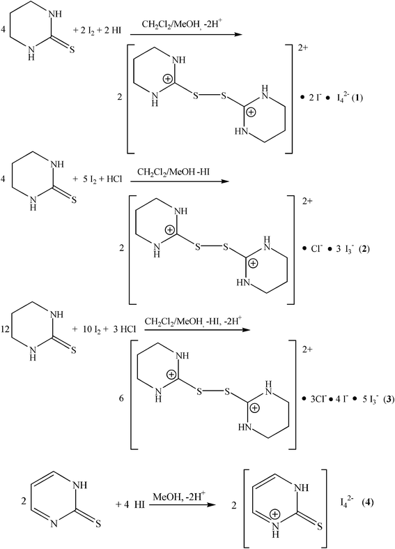
Among halogens, iodine, exhibits the highest tendency for catenation giving rise to a variety of poly-iodide anionic species of the general formulae: I2n+1− (n = 1–4), I2n+22− (n = 2–8), I2n+33− (n = 2–13), and I2n+44− (n = 3–11).1–3 Poly-iodides have very different structural and physical properties. However, the syntheses used can in general terms be described simply as the addition of iodine to an iodide in an appropriate reaction medium.1 This procedure can be varied in many different ways depending on how the iodine and iodide are mixed, the solvent used and the cation associated with the iodide.1–3 The direct reactions of di-iodine with heterocycles such as ketones, thiones or selones, on the other hand, are known to produce various types of iodine compounds, including charge transfer complexes, with “spoke structures” (D-I2), “extended spoke structures” (D-I2-I2), iodonium salts, mono-cationic disulfides and di-cationic disulfides or di-selenides with poly-iodides as counter anions.4–25 Recent reports outline the chemistry of such systems in detail.26–27In the course of our studies on the interaction of thioamides with di-iodine we synthesized and crystallographically characterized the ionic complexes formulae [2{(tHPMT)22+} 2(I−) (I42−)] (1), [2{(tHPMT)22+} Cl− 3(I3−)] (2), [6{(tHPMT)22+} 3(Cl−) 2(I−) 5(I3−)] (3) (tHPMT = 2-mercapto-3,4,5,6-tetrahydro-pyrimidine (Scheme 1)) and [2{(PMTH2)+} I42−] (4) (PMTH = 2-mercaptopyrimidine (Scheme 1)).
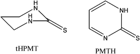 | ||
| Scheme 1 Ligands used; 2-mercapto-3,4,5,6-tetrahydro-pyrimidine (tHPMT) and 2-mercaptopyrimidine (PMTH). | ||
Results and discussion
Reactions: 2-mercapto-3,4,5,6-tetrahydro-pyrimidine (tHPMT) reacts with di-iodine in the presence of HI in 1![[thin space (1/6-em)]](https://www.rsc.org/images/entities/char_2009.gif) :
:![[thin space (1/6-em)]](https://www.rsc.org/images/entities/char_2009.gif) 1
1![[thin space (1/6-em)]](https://www.rsc.org/images/entities/char_2009.gif) :
:![[thin space (1/6-em)]](https://www.rsc.org/images/entities/char_2009.gif) 1 molar ratio in dichloromethane (eqn 1). Slow evaporation of the filtrate results in the formation of [2{(tHPMT)22+} 2(I−) (I42−)] (1) complex. Direct reaction of the same ligand tHPMT, with di-iodine in the presence of HCl in 1
1 molar ratio in dichloromethane (eqn 1). Slow evaporation of the filtrate results in the formation of [2{(tHPMT)22+} 2(I−) (I42−)] (1) complex. Direct reaction of the same ligand tHPMT, with di-iodine in the presence of HCl in 1![[thin space (1/6-em)]](https://www.rsc.org/images/entities/char_2009.gif) :
:![[thin space (1/6-em)]](https://www.rsc.org/images/entities/char_2009.gif) 2
2![[thin space (1/6-em)]](https://www.rsc.org/images/entities/char_2009.gif) :
:![[thin space (1/6-em)]](https://www.rsc.org/images/entities/char_2009.gif) 1 or 1
1 or 1![[thin space (1/6-em)]](https://www.rsc.org/images/entities/char_2009.gif) :
:![[thin space (1/6-em)]](https://www.rsc.org/images/entities/char_2009.gif) 1
1![[thin space (1/6-em)]](https://www.rsc.org/images/entities/char_2009.gif) :
:![[thin space (1/6-em)]](https://www.rsc.org/images/entities/char_2009.gif) 1 molar ratios, in dichloromethane, resulted in the formation of two crystalline complexes of formulae [2{(tHPMT)22+} Cl− 3(I3−)] (2) and [6{(tHPMT)22+} 3(Cl−) 2(I−) 5(I3−)] (3) (eqn (2–3)). The [2{(PMTH2)+} I42−] (4) complex has been prepared by reacting 2-mercaptopyrimidine with HI in 1
1 molar ratios, in dichloromethane, resulted in the formation of two crystalline complexes of formulae [2{(tHPMT)22+} Cl− 3(I3−)] (2) and [6{(tHPMT)22+} 3(Cl−) 2(I−) 5(I3−)] (3) (eqn (2–3)). The [2{(PMTH2)+} I42−] (4) complex has been prepared by reacting 2-mercaptopyrimidine with HI in 1![[thin space (1/6-em)]](https://www.rsc.org/images/entities/char_2009.gif) :
:![[thin space (1/6-em)]](https://www.rsc.org/images/entities/char_2009.gif) 1 molar ratio in dichloromethane (eqn 4).
1 molar ratio in dichloromethane (eqn 4).Crystal and molecular structures of [2{(tHPMT)22+} 2(I−) (I42−)] (1), [2{(tHPMT)22+} Cl− 3(I3−)] (2), [6{(tHPMT)22+} 3(Cl−) 2(I−) 5(I3−)] (3) and [2{(PMTH2)+} I42−] (4): ORTEP diagrams of complexes 1–4 and selected bond lengths and angles are shown in Fig. 1–4.
![(A) ORTEP diagram of 1 together with the atomic numbering scheme. Thermal ellipsoids drawn at the 50% probability level. Selected bond lengths (Å) and angles (°). S2A-S2B = 2.033(6), S2A-C2A = 1.79(1), N1A-C2A = 1.31(2), C2A-N3A = 1.27(2), S2B-C2B = 1.79(2), C2B-N3B = 1.31(2), N1B-C2B = 1.27(2), I3-I3 = 2.825(2), I2-I3 = 3.360(2) C2A-S2A-S2B-C2B = [104.6(7), I2-I3-I3 = 170.89(7)]. (B) Packing diagram of 1 as seen along the x direction.](/image/article/2012/RA/c2ra00013j/c2ra00013j-f1.gif) | ||
| Fig. 1 (A) ORTEP diagram of 1 together with the atomic numbering scheme. Thermal ellipsoids drawn at the 50% probability level. Selected bond lengths (Å) and angles (°). S2A-S2B = 2.033(6), S2A-C2A = 1.79(1), N1A-C2A = 1.31(2), C2A-N3A = 1.27(2), S2B-C2B = 1.79(2), C2B-N3B = 1.31(2), N1B-C2B = 1.27(2), I3-I3 = 2.825(2), I2-I3 = 3.360(2) C2A-S2A-S2B-C2B = [104.6(7), I2-I3-I3 = 170.89(7)]. (B) Packing diagram of 1 as seen along the x direction. | ||
![ORTEP diagram of 2 together with the atomic numbering scheme. Thermal ellipsoids drawn at the 50% probability level. Selected bond lengths (Å) and angles (°). S2A-S2B = 2.029(3), S2A-C2A = 1.80(1), N1A-C2A = 1.31(1), C2A-N3A = 1.29(1), S2B-C2B = 1.78(1), C2B-N3B = 1.32(1), N1B-C2B = 1.29(1), I1-I2 = 2.821(1), I2-I3 = 3.035(1), I4-I5 = 2.913(1), I1-I2-I3 = 178.44(3), I4-I5-I4 = 180 , C2A-S2A-S2B-C2B = [−95.1(4)]. (B) Packing diagram of 2 as seen along the z direction.](/image/article/2012/RA/c2ra00013j/c2ra00013j-f2.gif) | ||
| Fig. 2 ORTEP diagram of 2 together with the atomic numbering scheme. Thermal ellipsoids drawn at the 50% probability level. Selected bond lengths (Å) and angles (°). S2A-S2B = 2.029(3), S2A-C2A = 1.80(1), N1A-C2A = 1.31(1), C2A-N3A = 1.29(1), S2B-C2B = 1.78(1), C2B-N3B = 1.32(1), N1B-C2B = 1.29(1), I1-I2 = 2.821(1), I2-I3 = 3.035(1), I4-I5 = 2.913(1), I1-I2-I3 = 178.44(3), I4-I5-I4 = 180 , C2A-S2A-S2B-C2B = [−95.1(4)]. (B) Packing diagram of 2 as seen along the z direction. | ||
![(A) ORTEP diagram of 3 together with the atomic numbering scheme. Thermal ellipsoids drawn at the 50% probability level. Selected bond lengths (Å) and angles (°). S2A-S2B = 2.034(2), S2A-C2A = 1.779(7), N1A-C2A = 1.299(9), C2A-N3A = 1.314(9), S2B-C2B = 1.778(7), C2B-N3B = 1.308(9), N1B-C2B = 1.314(9), S2C-S2D = 2.027(3), S2C-C2C = 1.785(7), N1C-C2C = 1.305(9), C2C-N3C = 1.307(9), S2D-C2D = 1.786(7), C2D-N3D = 1.303(9), N1D-C2D = 1.302(9), S2E-S2F = 2.031(3), S2E-C2E = 1.781(7), N1E-C2E = 1.320(0), C2E-N3E = 1.309(9), S2F-C2F = 1.789(7), C2F-N3F = 1.315(9), N1F-C2F = 1.309(9), I1-I2 = 2.830(1), I2-I3 = 3.027(1), I4-I5 = 2.887(1), I5-I6 = 2.930(1), I7-I8 = 2.794(1), I8-I9 = 3.151(1), I10-I11 = 2.945(1), I11-I12 = 2.878(1), I13-I14 = 2.922(1), I15-I16 = 2.921(1), I1-I2-I3 = 179.65(4), I4-I5-I6 = 179.32(3), I7-I8-I9 = 179.36(3), I10-I11-I12 = 179.74(3), I13-I14-I13 = 180 I15-I16-I15 = 180, C2A-S2A-S2B-C2B = [−92.9(3)], C2C-S2C-S2D-C2D = [−96.2(3)], C2E-S2E-S2F-C2F = [92.7(3)]. (B) Packing diagram of 3 as seen along the x direction.](/image/article/2012/RA/c2ra00013j/c2ra00013j-f3.gif) | ||
| Fig. 3 (A) ORTEP diagram of 3 together with the atomic numbering scheme. Thermal ellipsoids drawn at the 50% probability level. Selected bond lengths (Å) and angles (°). S2A-S2B = 2.034(2), S2A-C2A = 1.779(7), N1A-C2A = 1.299(9), C2A-N3A = 1.314(9), S2B-C2B = 1.778(7), C2B-N3B = 1.308(9), N1B-C2B = 1.314(9), S2C-S2D = 2.027(3), S2C-C2C = 1.785(7), N1C-C2C = 1.305(9), C2C-N3C = 1.307(9), S2D-C2D = 1.786(7), C2D-N3D = 1.303(9), N1D-C2D = 1.302(9), S2E-S2F = 2.031(3), S2E-C2E = 1.781(7), N1E-C2E = 1.320(0), C2E-N3E = 1.309(9), S2F-C2F = 1.789(7), C2F-N3F = 1.315(9), N1F-C2F = 1.309(9), I1-I2 = 2.830(1), I2-I3 = 3.027(1), I4-I5 = 2.887(1), I5-I6 = 2.930(1), I7-I8 = 2.794(1), I8-I9 = 3.151(1), I10-I11 = 2.945(1), I11-I12 = 2.878(1), I13-I14 = 2.922(1), I15-I16 = 2.921(1), I1-I2-I3 = 179.65(4), I4-I5-I6 = 179.32(3), I7-I8-I9 = 179.36(3), I10-I11-I12 = 179.74(3), I13-I14-I13 = 180 I15-I16-I15 = 180, C2A-S2A-S2B-C2B = [−92.9(3)], C2C-S2C-S2D-C2D = [−96.2(3)], C2E-S2E-S2F-C2F = [92.7(3)]. (B) Packing diagram of 3 as seen along the x direction. | ||
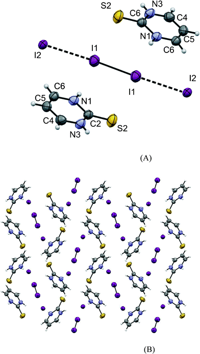 | ||
| Fig. 4 (A) ORTEP diagram of 4 together with the atomic numbering scheme. Thermal ellipsoids drawn at the 50% probability level. Selected bond lengths (Å) and angles (°). S2-C2 = 1.637(4), N1-C2 = 1.376(5), C2-N3 = 1.365(4), N3-C4 = 1.326(4), C4-C5 = 1.354(5), C5-C6 = 1.367(4), I1-I1 = 2.762(1), I1-I2 = 3.346(1), 176.47(1). (B) Packing diagram of 1 as see along the x direction. | ||
The asymmetric part of the unit cell of 1 consists of di-cationic species of di-protonated tHPMT disulfide (C8H16N4S2)2+ and one iodide and half of a tetra-iodide I42− anions counterparts. In the crystal structure, protonated tHPMT disulfide cations form parallel layers and the anions occupy the space between these layers (Fig. 1B).
The bond lengths and angles in the rings of tHPMT disulfide are close to values found in the structure of tHPMT.28 There is significant delocalization of the π electrons over the N–C–S fragment, which is confirmed by the angles on nitrogen and C2 atoms [122.8(14)–124.4(14)°], the shortening of the N–C2 bond lengths in the range 1.274(19)–1.307(19) Å and lengthening of the S2–C2 bond lengths [1.788(15) Å, 1.791(15) Å]. It has been found that the S–S bond length in disulfides highly depends on the C–S–S–C torsion angle.29 Thus, when the absolute value of the torsion angle C–S–S–C is less than 20° the average S–S bond length is about 2.070 Å, whereas for torsion angles between 75° and 105° (abs. value) the S–S bond length is reduced to 2.031 Å.29 In 1 the C2A-S2A-S2B-C2B torsion angle is 104.6(7)° and S2A-S2B bond length amounts to 2.033(6) what is consistent with the above rule. Both rings of tHPMT disulfide have a half-chair conformation. The C5 atoms deviate from the mean planes determined by the remaining ring atoms by −0.63(3) Å for C5A and −0.65(3) Å for-C5B.
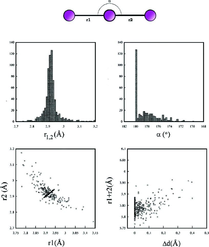
The tetra-iodide in the structure of [2{(tHPMT)22+} 2(I−) (I42−)] is symmetrical. The distance between I3 and I2 atoms is 3.360(2) Å, while the I3–I3 bond length is 2.825(3) Å. The elongation of the covalent iodine–iodine bond in tetra-iodide (in comparison to the I–I bond in I2) proves the secondary bond character of the I2–I3 contact. The most interesting feature of the tetra-iodide fragment in 1 is I2–I3–I2 angle (170.89(7)°). The deviation from the linearity for this tetra-iodide is greater than any such molecule described so far.1,18,30–40 The reason of such a deviation might be found in the crystal packing. Fig. 5 illustrates that terminal atoms I2 of the tetra-iodide are oriented toward the carbon atom C2A. Taking into account that π electrons in the N–C(S)–N system are delocalized, one can relate the interaction between those π electrons and the anion to the deflection of I42−. Moreover, this deflection can be also an effect of electrostatic interactions. Due to the protonation, the ring is positively charged, and this charge is probably located in the N–C(S)–N area. It is hard to determine which one of these two interactions has more significant impact on tetra-iodide, but they do not exclude each other. Most likely, both the electrostatic attraction and interaction between π electrons and the tetra-iodide anion cause this effect as this is evident by DFT calculations. Although there is not a charge transfer between the pyrimidine moiety and the poly-iodide chain, calculated Mulliken charges for the mentioned (Fig. 5A) N(1A)–C(2A)–N(3A) are −0.150, 0.352 and −0.158 respectively where for the pyrimidine close to I1, N(1B)–C(2B)–N(3B) are −0.172, 0.296 and −0.198 (a.u.). In addition Fig. 6 shows that the value of the angle θ1 of N(1A)–C(2A)–N(3A) is larger by 3 degrees compared to θ2. This is probably attributed to the increased p-orbital contribution to the I− directed orbital accompanying a smaller p-orbital contribution to the other bond-directed orbitals.41 Therefore terminal atom interactions are responsible for the non linear geometry of the tetra-iodide anion. Similar interactions have been noticed in the structure of [2{(tHPMT)22+} Cl− 3(I3−)] and in the poly-iodide salt of methimidazole.3
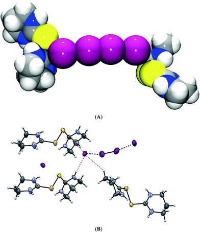 | ||
| Fig. 5 (A) The view of tetraiodide situated between two (tHPMT)22+ molecules. (B) The contacts of terminal iodine atom of tetraiodide in 1. | ||
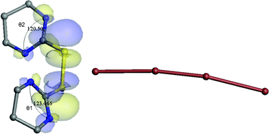 | ||
| Fig. 6 Schematic diagram of 1 (partial) showing HOMO-2 molecular orbital. | ||
The terminal atoms of I42− are also involved in the N1A–H1A⋯I2 hydrogen bond and C6A–H⋯I interaction (Fig. 5B). The other N–H groups of (tHPMT)22+ are also donors of hydrogen bonds with iodide as an acceptor. These three hydrogen bonds are not equal. The strongest among them is N1B–H1B⋯I1. In addition, in the described structure there is also a weak S⋯HC interaction (S2B–C4A 3.76(2) Å, S2B⋯H4B–C4A = 155°). Parameters of all the interactions present in the structure of [(tHPMT)2I− ½(I42−)] are shown in Table 1 and 2.
| D–H⋯A | d(D⋯A) | d(D–H) | d(A⋯H) | < (D–H⋯A) |
|---|---|---|---|---|
| N1A–H1A⋯I2 | 3.48(1) | 0.86 | 2.63 | 175 |
| N1B–H1B⋯I1 | 3.53(1) | 0.86 | 2.67 | 179 |
| N3A-–H3A⋯I1 | 3.59(1) | 0.86 | 2.86 | 141 |
| N3B–H3B⋯I1 | 3.64(1) | 0.86 | 2.91 | 144 |
| S⋯H–C | S⋯C | C–H | S⋯H | S⋯H–C |
|---|---|---|---|---|
| S2B⋯H4B–C4A | 3.76(2) | 0.97 | 2.86 | 155 |
| I⋯H–C | I⋯C | C–H | I⋯H | I⋯H–C |
| l⋯H6A–C6A | 3.93(2) | 0.97 | 3.11 | 144 |
Compound 2 is a double salt of tHPMT disulfide, with chloride and tri-iodide as counter anions (Fig. 2A). The asymmetric part of the unit cell of 2 consists of di-cationic species of protonated tHPMT disulfide (C8H16N4S2)2+ and one chloride and one and a half of tri-iodide I3− anions. The chloride and I5 atoms occupy the special positions at the different symmetry centers. The crystal packing of 2 is presented in Fig. 2B.
The bond lengths and angles in the tHPMT rings are close to values found in the structure of [(tHPMT)2I− ½(I42−)]. The only significant differences are the value of the C–S–S–C torsion angle and the C2–S2 bond lengths. In 2 the C2A–S2A–S2B–C2B torsion angle is −95.1(4)° and S2–C2 bond lengths are much more similar to each other than in the case of 1. They are 1.780(8) Å for S2B–C2B and 1.797(7) Å for S2A–C2A. As in 1 both rings of tHPMT disulfide have half-chair conformation. The C5 atoms deviate from the mean planes determined by the remaining ring atoms by 0.64(1) Å for C5A and −0.68(1) Å for C5B. Both symmetry-independent tri-iodides in 2 are linear. The bond angles centered on I5 and I2 atoms are 180° and 178.44(3)° respectively, which are typical values for tri-iodide (Fig. 7). While I4–I5–I4 tri-iodide is Ci symmetrical, the I4–I5 bond length is 2.9128(5) Å, and the I1–I2–I3 tri-iodide is highly asymmetrical [2.8205(7) Å for (I1-I2) and 3.0354(7) Å for (I2-I3)]. This shortening of the (I1–I2) bond lengths and lengthening of the (I2–I3) bond lengths in comparison with symmetrical I3− is connected with the involvement of the I3 atom in hydrogen bonding.
In the crystal of 2 there is huge variety of different intermolecular interactions. There are: quite strong N–H⋯Cl− and weaker N–H⋯I hydrogen bonds, weak S⋯I, S⋯Cl, C–H⋯I interactions and a previously mentioned interaction between terminal atom of poly-iodide and N–C(S)–N region.
The chloride anion acts as an acceptor for four hydrogen bonds laying in the same plane (Fig. 8) with N1–H1 groups of (tHPMT)22+. The distances between donors and acceptors are 3.152(8) Å for N1A ⋯Cl and 3.200(6) Å for N1B⋯Cl, whereas the N–H⋯Cl− angle is 173° for N1A–H1A⋯Cl− and 162° for N1B–H1B⋯Cl−. These parameters indicate that these hydrogen bonds are not equivalent. The N1A–H1A⋯Cl− hydrogen bond is shorter and more linear, and thus is probably stronger than N1B–H1B⋯Cl−. Another acceptor of a hydrogen bond is the terminal atom of asymmetric I3− (I3), which is involved in two hydrogen bonds with two N3–H fragments as donors. These bonds with D⋯A distances 3.612(7) Å and 3.670(6) Å are quite significant because they cause the asymmetry in the I1–I2–I3 tri-iodide. Furthermore, the I2–I3 bond elongation can be supported by the interaction between the I3 atom of triiodide and N–C(S)–N region [C2A⋯I3 is 3.679(7) Å], the nature of this interaction is discussed for 1.
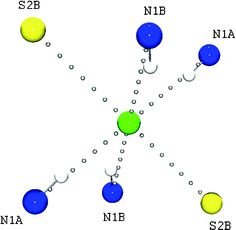 | ||
| Fig. 8 The view of Cl chloride interactions in 2. | ||
In 2 there is also halogen sulfur interaction. Both chloride and I4 atoms interact with the S2B sulfur atom; the distances are 3.676(2) Å for I4⋯S2B and 3.314(2) Å for Cl⋯S2B. Furthermore in the crystal structure of 2 there are also weak C–H⋯I interactions, which stabilize both symmetrical and asymmetrical tri-iodides. Parameters of all interactions present in the structure of [(tHPMT)2 ½Cl− I3− ½(I3−)] are shown in Table 3, 4 and 5.
| D–H⋯A | d(D⋯A) | d(D–H) | d(A⋯H) | < (D–H⋯A) |
|---|---|---|---|---|
| N1A-H1A⋯Cl | 3.152(8) | 0.86 | 2.30 | 173 |
| N1B-H1B⋯Cl | 3.200(6) | 0.86 | 2.37 | 162 |
| N3A-H3A⋯I3 | 3.612(7) | 0.86 | 2.89 | 143 |
| N3B-H3B⋯I3 | 3.670(6) | 0.86 | 2.90 | 150 |
| C–H⋯I | I⋯C | C–H | I⋯H | C–H⋯I |
|---|---|---|---|---|
| C6A-H6A′⋯l4 | 3.924(9) | 0.97 | 3.12 | 141 |
| C6B-H6B′⋯l1 | 4.00 (1) | 0.97 | 3.10 | 156 |
| C4B-H4B⋯l2 | 3.881(8) | 0.97 | 3.18 | 131 |
| C5A-H5A⋯l2 | 3.940(8) | 0.97 | 3.16 | 139 |
| Cl⋯S | I⋯S | Cl⋯S–S | I⋯S–S | |
|---|---|---|---|---|
| [((tHPMT)2)2+ (I3−) (I3−,Cl−)0.5] | 3.314(2) | 3.676(2) | 163.2(1) | 93.8(1) |
| [(((tHPMT)2)2+)3(Cl−)1.5(I−)2(I3−)2.5] | 3.444(2) | 3.690(2) | 163.80(9) | 98.80(8) |
| 3.507(2) | 3.590(2) | 166.4(1) | 94.90(8) | |
| 3.482(2) | 3.705(2) | 166.3(1) | 102.67(8) | |
| 3.435(2) | 3.769(2) | 162.9(1) | 102.31(8) |
HOMO and LUMO molecular orbitals for the case of 2 are shown in Fig. 9.
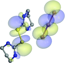 | ||
| Fig. 9 HOMO and LUMO molecular orbitals of 2. | ||
The structural unit of compound 3 consists of three molecules of dicationic species of protonated tHPMT disulfide, and one hexaiodide, four triiodide, four iodide and four chloride anions (Fig. 3a). All anions occupy the special positions on the mirror plane, and I14, I16 and Cl3 atoms are additionally on two-fold axes, so their position has altogether 2/m symmetry. The position of atom Cl1 is only half occupied, which is the reason for high values of thermal ellipsoid parameters and high residual peaks (4.82 and 4.28) in the neighborhood of Cl1. Moreover it is probably also positionally disordered, therefore it won't be taken into account in the interactions discussion. The bond lengths and angles in the tHPMT rings of all molecules are close to values found in the structure of 2, even C2–S2–S2–C2 torsion angles are close to this in 2 (−92,9(3)°, −92.7(3)°, −96,2(3)°). That leads us to a supposition that the environment is a determining factor in the mutual orientation of the tHPMT rings in these disulfides and that the halogen–sulfur interaction has great influence on an absolute value of C2–S2–S2–C2 torsion angle. As in 1 and 2, in all three molecules of 3 both rings of tHPMT disulfide have a half-chair conformation. The C5 atoms deviate from the mean planes determined by the remaining ring atoms by 0.67(1) Å for C5A, −0.67(1) Å for C5B, 0.67(1) Å for C5C, −0.64(1) Å for C5D, −0.66(1) Å for C5E, 0.67(1) Å for C5F. As in 1 in the crystal structure of 3, protonated tHPMT disulfide cations form a parallel layers and the anions, which occupy the space between these layers, are lying in the same plane—in this case it is the exact mirror plane (Fig. 3b). This is interesting especially from the standpoint of charge distribution.
The crystal structure of 3 contains both symmetrical (I13–I14–I13, I15–I16–I15) and asymmetrical tri-iodides where the extent of asymmetry is diverse. Two of the tri-iodides (I1–I2–I3, I7–I8–I9) show a relatively large difference in bond lengths (ca. 0.2 Å) and in another two (I4–I5–I6, I10–I11–I12) the I–I bonds are more balanced (ca. 0.05 Å). In addition the analysis of the I⋯I contacts within the anionic layer leads to the observation that the I7⋯I10 contact is short enough (3.667(1) Å) to be classified as a secondary bond. This results in the formation of an I62− di-anion (I9–I8–I7⋯ I10–I11–I12). The interaction between orbitals is shown in Fig. 10 where the interaction between the two adjacent I3 anions is depicted in LUMO+3.
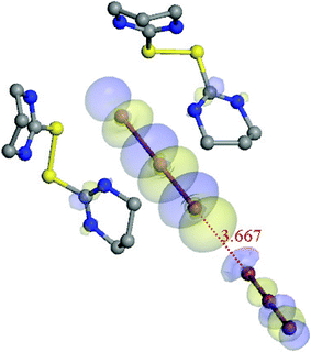 | ||
| Fig. 10 LUMO + 3 of adduct 3. | ||
Moreover the I7 atom of hexa-iodide interacts with the I4–I5–I6 tri-iodide and the length of the contact is 3.8532(1) Å. Although the I7⋯I10 distance is smaller than the sum of van der Waals radius we think that it would be too far-reaching to recognize that structure as I93− and this is also confirmed by minor interactions among the two moieties in the DFT calculations.
Besides I⋯I interactions, in 3 there are N–H⋯Cl− and N–H⋯I hydrogen bonds and S⋯I, S⋯Cl, C–H⋯I contacts. In the crystal structure of 3 (similar to 1 and 2) N–H groups of (tHPMT)22+ act as donors of hydrogen bonds, while chloride, iodide and terminal atoms of tri-iodide (I9,I3) are the acceptors. Each of two chloride atoms (Cl3 and Cl4) interacts with four N–H groups co-planar with the certain anion (Fig. 11A). The third chloride atom Cl2 is also an acceptor of four hydrogen bonds, but in contrast to Cl3 and Cl4, it does not lie in the plane defined by N–H groups (Fig. 11B). We found out that the factor, which determines the relative position of the chloride with respect to the hydrogen bond donors, is the number of neighboring (in the inter-atomic contact distance) sulfur atoms (four in the case of Cl3 and Cl4, two for Cl2). The effect of the Cl−⋯S interaction on hydrogen bond geometry confirms the importance of the halogen–sulfur interaction in crystal packing.
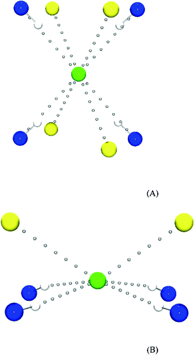 | ||
| Fig. 11 (A) The view of Cl4 Cl3 chloride interactions in 3. (B) The view of Cl2 chloride interactions in 3. | ||
Other acceptors of hydrogen bonds, I18, I19, I20 iodides are involved in two hydrogen bonds and I17 in four hydrogen bonds. These iodides are not involved in any other interactions. The terminal I3 and I9 atoms of I1–I2–I3 and I9–I8–I7⋯I10–I11–I12 poly-iodides are also involved in hydrogen bond and as in the case of 2 these interactions cause significant asymmetry in those poly-iodides.
The subtle asymmetry of I4–I5–I6 tri-iodide is probably caused by the halogen–sulfur interaction, in which the terminal I6 atom is involved (Fig. 12). In the case of I10–I11–I12 , the I10–I11 bond length is the longer one, despite the fact that the I12 is involved in the I⋯S interaction. This is probably caused by transferring the charge from the I7 to I10 iodine atom, which confirms the argument of the hexa-iodide structure formation. There is also a weak C–H⋯I interaction, which might stabilize the I62−, but which is most probably of secondary character. The parameters of all interactions found in the complicated structure of [(((tHPMT)2)2+)3(Cl−)1.5(I−)2(I3−)2.5] are shown in Table 5, 6 and 7.
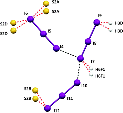 | ||
| Fig. 12 The view hexa-, tri iodide interactions in 3 with bond lengths together with the atomic numbering scheme. Selected bond lengths (Å) and angles (°): a = 3.667(1), b = 3.852(1), I4-I5 = 2.887(1), I5-I6 = 2.930(1), I7-I8 = 2.794(1), I8-I9 = 3.151(1), I10-I11 = 2.945(1), I11-I12 = 2.878(1). | ||
| D–H⋯A | d(D⋯A) | d(D–H) | d(A⋯H) | < (D–H⋯A) |
|---|---|---|---|---|
| N1A–H1A⋯Cl4 | 3.138(6) | 0.86 | 2.28 | 168 |
| N3B–H3B⋯Cl2 | 3.151(6) | 0.86 | 2.30 | 162 |
| N3C–H3C⋯Cl2 | 3.075(6) | 0.86 | 2.22 | 165 |
| N3E–H3E⋯Cl4 | 3.141(6) | 0.86 | 2.29 | 164 |
| N1F–H1F⋯Cl3 | 3.1426) | 0.86 | 2.4 | 172 |
| N3F–H3F⋯I17 | 3.543(6) | 0.86 | 2.78 | 146 |
| N1B–H1B⋯I18 | 3.563(6) | 0.86 | 2.80 | 146 |
| N3A–H3A⋯I19 | 3.547(6) | 0.86 | 2.78 | 146 |
| N1E–H1E⋯I20 | 3.555(6) | 0.86 | 2.9 | 143 |
| N1C–H1C⋯I3 | 3.621(5) | 0.86 | 2.84 | 148 |
| N3D–H3D⋯I9 | 3.636(6) | 0.86 | 2.87 | 146 |
| C–H⋯I | I⋯C | C–H | I⋯H | C–H⋯I |
|---|---|---|---|---|
| C6A–H6F1⋯l7 | 3.908(7) | 0.97 | 3.03 | 149 |
The asymmetric part of the unit cell of 4 consists of cationic species of protonated PMT (C4H5N2S1)+ and a half of the tetra-iodide I42−. The crystal packing of 4 is presented in Fig. 4B.
The bond lengths and angles in the PMT ring are close to values found in the structure of PMT.42 The ring of PMT is approximately planar, the largest deviation from the last squares plane is 0.017(2) for the C5 atom.
The tetra-iodide fragment is Ci symmetrical, as it occupies the special position on the inversion center in the space group P21/n. The distance between I2 and I1 atoms is 3.346(1) Å, while the I1–I1 bond length is 2.7616(4) Å. Although the distance between terminal and central iodine atoms is even smaller than in the case of 1, the elongation of the covalent iodine–iodine bond is significantly smaller in 4. That leads to the conclusion that in the case of tetra-iodide the most important factor in the formation of CT complexes is not the distance between the terminal and the central iodine atoms in I42− but the interactions in which the terminal atoms are involved. Similar to 1, the tetra-iodide fragment in 4 is not completely linear, the I2-I3-I2 angle is 176.41(1)°. Although in 4 the deviation from the linearity is significantly smaller than in 1, the reason for the deviations is probably similar in both these cases although it seems that in 4 central atoms also play a role counteracting the distortions also interacting with the adjacent pyrimidines (Fig. 13). The terminal atoms of tetra-iodides are oriented towards the carbon atom C6 of the protonated ring, and in the case of 4, they interact with five molecules of protonated PMT by different intermolecular contacts with A and B molecules (Fig. 14) by interacting with protonated aromatic ring (I2⋯C6 distances 3.638(3) Å for B and 3.699(3) for A) with C and D by hydrogen bonds and with E by C–H⋯I contact. The parameters of hydrogen bonding and C–H⋯I interactions found in the structure of [(PMT)− ½(I42−)] are shown in Table 8.
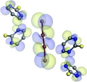 | ||
| Fig. 13 HOMO and LUMO molecular orbitals regarding 4. | ||
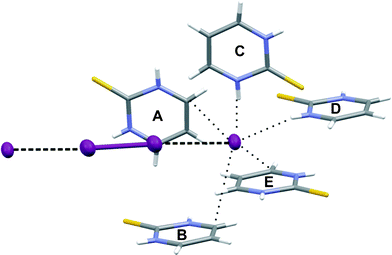 | ||
| Fig. 14 The contacts of terminal iodine atom of tetraiodide in 4. | ||
![Correlation between ν(I–I) Raman bands of the adducts [{(bztzdtH)I2}·I2]4 (7; bztzdtH- benzothiazole-2-thione) ν(I–I) = 143.7 cm−1 [(bztzdtH)I2]4 (8) ν(I-I) = 147 cm−1, [ptc·I2]12 (9; ptc = 1,3-dithiacyclohexane-2-thione) ν(I–I) = 164 cm−1; [ttb·I2]12 (10; ttb = 4,5-ethylenedithio-1,3-dithiole-2-thione) ν(I–I) = 162 cm−1; [mdtt·I2]47 [11; mdtt = 4,5-bis(methylsulfanyl)-1,3-dithiole-2-thione] ν(I–I) = 136 cm−1; [mbit·I2]13 [12; mbit = 1,1-methylenebis(3-methyl-4-imidazoline-2-thione)] ν(I–I) = 152 cm−1; [bzoxtH·I2]48 (13;bzoxtH = benzoxazole-2-thione) ν(I–I) = 176 cm−1; [dmimdtH·I2]49 (14; dmimdtH = 5,5-dimethylimidazoline-2,4-dithione) ν(I–I) = 152 cm−1 and compounds 1 ν(I–I) = 152 ν(I–I) = 160.54 cm−1 cm−1 and 3a ν(I–I) = 157.75 cm−1, 3b ν(I–I) = 140.81 cm−1, 3c ν(I–I) = 115.83 cm−1.](/image/article/2012/RA/c2ra00013j/c2ra00013j-f15.gif) | ||
| Fig. 15 Correlation between ν(I–I) Raman bands of the adducts [{(bztzdtH)I2}·I2]4 (7; bztzdtH- benzothiazole-2-thione) ν(I–I) = 143.7 cm−1 [(bztzdtH)I2]4 (8) ν(I-I) = 147 cm−1, [ptc·I2]12 (9; ptc = 1,3-dithiacyclohexane-2-thione) ν(I–I) = 164 cm−1; [ttb·I2]12 (10; ttb = 4,5-ethylenedithio-1,3-dithiole-2-thione) ν(I–I) = 162 cm−1; [mdtt·I2]47 [11; mdtt = 4,5-bis(methylsulfanyl)-1,3-dithiole-2-thione] ν(I–I) = 136 cm−1; [mbit·I2]13 [12; mbit = 1,1-methylenebis(3-methyl-4-imidazoline-2-thione)] ν(I–I) = 152 cm−1; [bzoxtH·I2]48 (13;bzoxtH = benzoxazole-2-thione) ν(I–I) = 176 cm−1; [dmimdtH·I2]49 (14; dmimdtH = 5,5-dimethylimidazoline-2,4-dithione) ν(I–I) = 152 cm−1 and compounds 1 ν(I–I) = 152 ν(I–I) = 160.54 cm−1 cm−1 and 3a ν(I–I) = 157.75 cm−1, 3b ν(I–I) = 140.81 cm−1, 3c ν(I–I) = 115.83 cm−1. | ||
| D–H⋯A | d(D⋯A) | d(D–H) | d(A⋯H) | < (D–H⋯A) |
|---|---|---|---|---|
| N1–H1⋯I2 | 3.498(2) | 0.84(4) | 2.69(4) | 162(4) |
| N3–H3⋯I2 | 3.533(3) | 0.74(4) | 2.81(4) | 166(3) |
| 136(3) | ||||
| C4–H4⋯l2 | 3.820(3) | 0.91(4) | 3.11(4) |
HOMO and LUMO molecular orbitals regarding 4 are depicted in Fig. 13.
Vibrational Spectroscopy: Free iodine shows a vibrational band at 180 cm−1 ν(I-I) in the Raman spectra. When I2 is coordinated to the donor the band shifts to lower frequencies as an effect of reduction of I-I bond strength. The spectra of symmetrical I3− shown the Raman active symmetrical stretching mode at 110 cm−1,3–10 and there are no signals of either asymmetric stretching vibration (ν3), or the deformational vibrations (ν2), which occur for the asymmetrical tri-iodides. Moreover, higher poly-iodides are recognized as a combination of tri-iodides and/or iodides with I2 .
The Raman spectra of compounds 1 and 3, recorded in the 250–50 cm−1 region, show an intense band at 160.54 cm−1 for 1 and at 115.83, 140.81 and 157.75 cm−1 respectively for 3. In 1 the single Raman band at 160.54 cm−1 is attributed to the ν1(I-I) vibration of I3-I3 moiety coordinated by I2 atoms. The single, sharp band shifted to lower frequencies confirms the tetra-iodide structure formation. In case of 3 intensive band at 115.83 cm−1 is recognized as ν1(I-I), while peaks at 140.81 cm−1 and 157.75 cm−1 are attributed to the stretching (ν3), and deformational (ν2) vibrations. Fig. 12 correlates I-I bond distances vs. v(I-I) vibrational bands.
Conclusions
Structures containing poly-iodides are rather common, but examples of poly-iodides longer than tri-iodides are relatively scarce. For instance, there is only a handful known structures with tetra-iodide fragment and only six such structures with organic cations can be found in the CDB.31,37,39,40Tetra-iodide in the structure of 1 is symmetrical, with I3–I2 = 3.355(1) Å and I3–I3′ = 2.831(1) Å. The elongation of the covalent iodine–iodine bond proves the secondary bond character of I2⋯I3 contact. Moreover, the deviation from the linearity for this di-anion [I2–I3–I2 = 171.01(4)°] is greater than in any such molecule described so far.1,18,30–40 The reasons of this are most probably (i) electrostatic attraction and (ii) interaction between π electrons and tetra-iodide terminal atom. The intermolecular interactions of the same terminal iodine atom of tetra-iodide in 4 are also relevant. Most likely they are responsible for creating the I42− in this structure, which manifests itself in a relatively small elongation of a central iodine–iodine bond (2.762(1) Å) despite the close I2 and I1 contact (3.346(1) Å). Even more exceptional than tetra-iodide is the hexa-iodide fragment, present in structure 3. The I7⋯I10 contact is short enough (3.666(1) Å) to be classified as a secondary bond, which results in the formation of a I62− di-anion (I9–I8–I7⋯I10–I11–I12). By preparing compounds 1 and 2 with the same procedure using different quantity of iodine (in 2 two times more than in 1) it has been confirmed that the amount of iodine used in the reaction significantly affects the resulting product.
Experimental
Materials and instruments: All solvents used were reagent grade. Di-iodine (Aldrich), hydroiodic acid (57%) (Aldrich), hydrochloric acid (38%) (Merck) 3,4,5,6-tetrahydro-2-pyrimidinethiol (Aldrich), 2-pyrimidinethiol (Aldrich) were used with no further purification. Melting points were measured in open tubes with a Stuart scientific apparatus and are uncorrected. Infra-red spectra in the region 4000–370 cm−1 were obtained from KBr with a Perkin-Elmer Spectrum GX FT-IR spectrophotometer. The 1H NMR spectra were recorded with a Bruker AC250 MHFT NMR instrument in DMSO-d6 solutions. Chemical shifts δ, given in ppm, are referenced to internal TMS (1H).
Synthesis and crystallization of
1
–4: Compound 1 was prepared by mixing dichloromethane solutions of di-iodine with methanol solution of tHPMT with HI in molar ratio (1![[thin space (1/6-em)]](https://www.rsc.org/images/entities/char_2009.gif) :
:![[thin space (1/6-em)]](https://www.rsc.org/images/entities/char_2009.gif) 1
1![[thin space (1/6-em)]](https://www.rsc.org/images/entities/char_2009.gif) :
:![[thin space (1/6-em)]](https://www.rsc.org/images/entities/char_2009.gif) 1) under air at 0 °C with continuous stirring for 2–3 h. The solution was then filtered and the resulting clear solution was kept in the refrigerator for several days. Dark crystals of the complexes suitable for single-crystal analysis by X-ray crystallography were then grown and filtered off.
1) under air at 0 °C with continuous stirring for 2–3 h. The solution was then filtered and the resulting clear solution was kept in the refrigerator for several days. Dark crystals of the complexes suitable for single-crystal analysis by X-ray crystallography were then grown and filtered off.
Compound 1: Yield: 0.076 g, (40%); mp: 125–126 °C. 1H-NMR (DMSO): δ = 9.115 [s, 4 H, H–N1A, H–N1B, H–N3A, H–N3B, 3.287[t, 8H, H2C4A, H2C4B, H2C6A H2C6B], 1.831 [m, 4 H, H2C5A, H2C5B]. IR (cm−1): 3215s, 3062s, 2946vs, 1629vs, 1557vs, 1554vs, 1426 s, 1304 m, 1197 m, 714 m.
Compound 2 was prepared by mixing dichloromethane solutions of di-iodine with methanol solution of tHPMT with HCl in molar ratio (2![[thin space (1/6-em)]](https://www.rsc.org/images/entities/char_2009.gif) :
:![[thin space (1/6-em)]](https://www.rsc.org/images/entities/char_2009.gif) 1
1![[thin space (1/6-em)]](https://www.rsc.org/images/entities/char_2009.gif) :
:![[thin space (1/6-em)]](https://www.rsc.org/images/entities/char_2009.gif) 1) in the case of complex. Yield: 0.02 g (13,23%) mp: 102 °C. IR (cm−1): 3147 s, 3070 s, 2957 s, 1635vs, 1558vs, 1419 s, 1312 s, 1199 s, 727 s.
1) in the case of complex. Yield: 0.02 g (13,23%) mp: 102 °C. IR (cm−1): 3147 s, 3070 s, 2957 s, 1635vs, 1558vs, 1419 s, 1312 s, 1199 s, 727 s.
Compound 3 was prepared by mixing dichloromethane solutions of di-iodine with methanol solution of tHPMT with HCl in molar ratio (1![[thin space (1/6-em)]](https://www.rsc.org/images/entities/char_2009.gif) :
:![[thin space (1/6-em)]](https://www.rsc.org/images/entities/char_2009.gif) 1
1![[thin space (1/6-em)]](https://www.rsc.org/images/entities/char_2009.gif) :
:![[thin space (1/6-em)]](https://www.rsc.org/images/entities/char_2009.gif) 1) in the case of complex 1. Yield: 0.06 g (25,97%) mp: 122 °C. 1H-NMR (DMSO): δ = 9.702 [s, 4 H, H–N1A, H–N1B, H–N3A, H–N3B] 3.360 [t, 8H, H2C4A, H2C4B, H2C6A H2C6B], 1.852 [m, 4 H, H2C5A, H2C5B]. IR (cm−1): 3215 s, 3132 s, 3062 s, 2945 s, 1629vs, 1553vs, 1418 s, 1304 s, 1196 s, 714w.
1) in the case of complex 1. Yield: 0.06 g (25,97%) mp: 122 °C. 1H-NMR (DMSO): δ = 9.702 [s, 4 H, H–N1A, H–N1B, H–N3A, H–N3B] 3.360 [t, 8H, H2C4A, H2C4B, H2C6A H2C6B], 1.852 [m, 4 H, H2C5A, H2C5B]. IR (cm−1): 3215 s, 3132 s, 3062 s, 2945 s, 1629vs, 1553vs, 1418 s, 1304 s, 1196 s, 714w.
Compound 4 was prepared by adding hydroiodic acid to a methanol solution of PMT in a molar ratio 1![[thin space (1/6-em)]](https://www.rsc.org/images/entities/char_2009.gif) :
:![[thin space (1/6-em)]](https://www.rsc.org/images/entities/char_2009.gif) 1. The solution was then filtered and the resulting clear solution was kept in the refrigerator for several days. Several dark red crystals of the complexes suitable for single-crystal analysis by X-ray crystallography were then grown and filtered off.
1. The solution was then filtered and the resulting clear solution was kept in the refrigerator for several days. Several dark red crystals of the complexes suitable for single-crystal analysis by X-ray crystallography were then grown and filtered off.
Crystal data: X-Ray diffraction data were collected for 1 and 4 at 293(2) K and for 2, 3 at 100(1) K on XCALIBUR diffractometer with EOS detector using graphite-filtered Mo Kα radiation (λ = 0.71073 Å) The data were corrected for Lorentz-polarization as well as for absorption effects.43 The calculations were mainly performed within the WinGX program system.44 The structures were solved with SIR9245 and refined with the full-matrix least-squares procedure on F2 by SHELXL97.46 Non-hydrogen atoms were refined anisotropically, hydrogen atoms in 1–3 were located at calculated positions and were also freely refined with the isotropic thermal parameters, while in case of 4 hydrogen atoms were located by difference maps and were refined isotropically. For molecular graphics the programs ORTEP3v244 and Mercury 2.247 were used. Relevant crystal data are listed in Table 9, together with refinement details.
| Formula | C8H16N4S2I3 | C16H32ClI9N8S4 | C96H192Cl6I38N48S24 | C4H5N2SI2 |
|---|---|---|---|---|
| Mr | 613.07 | 1642.29 | 7823.32 | 366.96 |
| Crystal system, space group | Orthorhombic, P21212 | Monoclinic, P21/c | Orthorhombic, Pnnm | Monoclinic, P21/n |
| a | 12.211(1) Å | 14.502(2) Å | 20.982(2) Å | 8.2469(2) Å |
| b | 25.342(2) Å | 12.310(2) Å | 42.307(2) Å | 11.3129(2) Å |
| c | 5.6906(5) Å | 12.354(2) Å | 12.4442 10) Å | 10.3137(2) Å |
| β | — | 111.59 (1)° | — | 106.79 (1)° |
| V | 1761.0(3) Å3 | 2050.8(2) Å3 | 11![[thin space (1/6-em)]](https://www.rsc.org/images/entities/char_2009.gif) 046.7(17) Å3 046.7(17) Å3 |
921.21(6) Å3 |
| Cell parameters from reflections | 12![[thin space (1/6-em)]](https://www.rsc.org/images/entities/char_2009.gif) 527 527 |
3487 | 34![[thin space (1/6-em)]](https://www.rsc.org/images/entities/char_2009.gif) 508 508 |
19![[thin space (1/6-em)]](https://www.rsc.org/images/entities/char_2009.gif) 897 897 |
| R int | 0.085 | 0.063 | 0.024 | 0.024 |
| θ | 2.9–27.9° | 2.5–29.0° | 2.9–27.7° | 3.1–27.9° |
| R[F2 > 2σ (F2)] | 0.066 | 0.037 | 0.044 | 0.020 |
| wR(F2) | 0.183 | 0.045 | 0.089 | 0.042 |
| S | 1.07 | 0.88 | 1.11 | 1.12 |
| μ | 5.55 mm−1 | 7.09 mm−1 | 5.66 mm−1 | 6.98 mm−1 |
| T | 293 K | 100 K | 100 K | 293 K |
| Z | 4 | 2 | 2 | 4 |
| F(000) | 1132 | 1484 | 7208 | 660 |
| measured reflections | 25![[thin space (1/6-em)]](https://www.rsc.org/images/entities/char_2009.gif) 005 005 |
14![[thin space (1/6-em)]](https://www.rsc.org/images/entities/char_2009.gif) 097 097 |
50![[thin space (1/6-em)]](https://www.rsc.org/images/entities/char_2009.gif) 417 417 |
26![[thin space (1/6-em)]](https://www.rsc.org/images/entities/char_2009.gif) 655 655 |
| independent reflections | 3483 | 4792 | 12![[thin space (1/6-em)]](https://www.rsc.org/images/entities/char_2009.gif) 664 664 |
2120 |
| Reflections with I > 2σ(I) | 2914 | 2441 | 10![[thin space (1/6-em)]](https://www.rsc.org/images/entities/char_2009.gif) 382 382 |
1922 |
| (Δ/σ)max | 0.001 | 0.066 | 0.001 | 0.0001 |
| Δ ρmax | 2.99 e Å−3 | 1.35 e Å−3 | 4.83 e Å−3 | 0.58 e Å−3 |
| Δ ρmin | −1.08 e Å−3 | −1.30 e Å−3 | −2.75 e Å−3 | −0.65 e Å−3 |
| Number of parameters | 154 | 175 | 525 | 102 |
Crystallographic data (excluding structure factors) for the structural analysis have been deposited with the Cambridge Crystallographic Data Centre, No. CCDC-843![[thin space (1/6-em)]](https://www.rsc.org/images/entities/char_2009.gif) 964 (1), 843
964 (1), 843![[thin space (1/6-em)]](https://www.rsc.org/images/entities/char_2009.gif) 963 (2), 843
963 (2), 843![[thin space (1/6-em)]](https://www.rsc.org/images/entities/char_2009.gif) 962 (3) and 843
962 (3) and 843![[thin space (1/6-em)]](https://www.rsc.org/images/entities/char_2009.gif) 961 (4). Copies of this information may be obtained free of charge from: The Director, CCDC, 12 Union Road, Cambridge, CB2 1EZ, UK. Fax: +44(1223)336-033, e-mail:deposit@ccdc.cam.ac.uk, or www: www.ccdc.cam.ac.uk.
961 (4). Copies of this information may be obtained free of charge from: The Director, CCDC, 12 Union Road, Cambridge, CB2 1EZ, UK. Fax: +44(1223)336-033, e-mail:deposit@ccdc.cam.ac.uk, or www: www.ccdc.cam.ac.uk.
Computational details
Quantum chemical DFT energy calculations were carried out using the DMol3 algorithm.48,49 The generalized gradient corrections (GGA) to the local density approximation were employed with the hybrid exchange–correlation BLYP functional. The DNP double numerical plus polarization basis set, which is comparable to the 6-31G(d,p) Gaussian type basis set, was used. Calculations were based on the molecular geometries acquired by X-ray diffraction methods. Orbital cutoff was set to 4.4 Å.Acknowledgements
This work was carried out in partial fulfilment of the requirements for the M.Sc. theses of Ms A.M.O. and carried out in both Universities of Ioannina and A. Mickiewicz within the framework of the ERASMUS program.References
- P. H. Svensson and L. Kloo, Chem. Rev., 2003, 103, 1649–1684 CrossRef CAS.
- P. D. Boyle and S. M. Godfrey, Coord. Chem. Rev., 2001, 223, 265–299 CrossRef CAS.
- P. Deplano, J. R. Ferraro, M. L. Mercuri and E. F. Trogu, Coord. Chem. Rev., 1999, 188, 71–95 CrossRef CAS.
- (a) V. Daga, S. K. Hadjikakou, N. Hadjiliadis, M. Kubicki, J. H. Z. dos Santos and I. S. Butler, Eur. J. Inorg. Chem., 2002, 1718–1728 CrossRef CAS; (b) I.-E. Parigoridi, G. J. Corban, S. K. Hadjikakou, N. Hadjiliadis, N. Kourkoumelis, G. Kostakis, V. Psycharis and C. P. Raptopoulou, Dalton Trans., 2008, 5159–5165 RSC.
- C. D. Antoniadis, G. Corban, S. K. Hadjikakou, N. Hadjiliadis, M. Kubicki, S. Warner and I. S. Butler, Eur. J. Inorg. Chem., 2003, 1635–1640 CrossRef CAS.
- C. D. Antoniadis, S. K. Hadjikakou, N. Hadjiliadis, M. Kubicki and I. S. Butler, Eur. J. Inorg. Chem., 2004, 4324–4329 CrossRef CAS.
- C. D. Antoniadis, S. K. Hadjikakou, N. Hadjiliadis, M. Kubicki and I. S. Butler, New J. Chem., 2005, 29, 714–720 RSC.
- (a) G. J. Corban, S. K. Hadjikakou, N. Hadjiliadis, M. Kubicki, E. R. T. Tiekink, I. S. Butler, E. Drougas and A. M. Kosmas, Inorg. Chem., 2005, 44, 8617–8627 CrossRef CAS; (b) C. D. Antoniadis, S. K. Hadjikakou, N. Hadjiliadis, A. Papakyriakou, M. Baril and I. S. Butler, Chem.–Eur. J., 2006, 12, 6888–6897 CrossRef CAS.
- S. K. Hadjikakou and N. Hadjiliadis, Bioinorganic Chemistry and Applications, Volume 2006, Article ID 60291, Pages, 1–10 Search PubMed.
- J. H. Z. dos Santos, I. S. Butler, V. Daga, S. K. Hadjikakou and N. Hadjiliadis, Spectrochim. Acta, Part A, 2002, 58, 2725–2735 CrossRef.
- M. Esseffar, W. Bouab, A. Lamsabhi, J. L. M. Abboud, R. Notario and M. Yanez, J. Am. Chem. Soc., 2000, 122, 2300–2308 CrossRef CAS.
- F. Bigoli, P. Deplano, A. Ienco, C. Mealli, M. L. Mercuri, M. A. Pellinghelli, G. Pintus, G. Saba and E. F. Trogu, Inorg. Chem., 1999, 38, 4626–4636 CrossRef CAS.
- F. Bigoli, P. Deplano, M. L. Mercuri, M. A. Pellinghelli, A. Sabatini, E. F. Trogu and A. Vacca, J. Chem. Soc., Dalton Trans., 1996, 3583–3598 RSC.
- F. Freeman, J. W. Zi1ler, H. N. Po and M. C. Keindl, J. Am. Chem. Soc., 1988, 110, 2586–2591 CrossRef CAS.
- D. Arzei, P. Deplano, E. F. Trogu, F. Bigou, M. A. Pellinghelli and A. Vacca, Can. J. Chem., 1988, 66, 1483–1489 CrossRef.
- F. Cristiani, F. A. Devillanova, A. Diaz and G. Verani, J. Chem. Soc. Perkin Trans., 1984, 1383–1386 CAS.
- F. A. Devillanova and G. Verani, Tetrahedron, 1979, 35, 511–514 CrossRef CAS.
- M. C. Aragoni, M. Arca, F. Demartin, F. A. Devillanova, A. Garau, F. Isaia, V. Lippolis and G. Verani, J. Am. Chem. Soc., 2002, 124, 4538–4539 CrossRef CAS.
- P. D. Boyle and S. M. Godfrey, Coord. Chem. Rev., 2001, 223, 265–299 CrossRef CAS.
- P. Deplano, J. R. Ferraro, M. L. Mercuri and E. F. Trogu, Coord. Chem. Rev., 1999, 188, 71–95 CrossRef CAS.
- P. Deplano, F. A. Devillanova, J. R. Ferraro, F. Isaia, V. Lippolis and M. L. Mercuri, Appl. Spectrosc., 1992, 46, 1625–1629 CrossRef CAS.
- D. R. Morris and L. P. Hager, J. Biol. Chem., 1966, 241, 3582–3589 CAS.
- M. J. Berry, J. D. Kieffer, J. W. Harney and P. R. Larsen, J. Biol. Chem., 1991, 266, 14155–14158 CAS.
- W. W. du Mont, G. Mugesh, C. Wismach and P. G. Jones, Angew. Chem., Int. Ed., 2001, 40, 2486–2489 CrossRef CAS.
- W. T. Pennington, T. W. Hanks and H. D. Arman, Struct Bond (HALOGEN BONDING: FUNDAMENTALS AND APPLICATIONS), 2008, 126, 65–104 CAS.
- C. Ouvrard, J.-Y. Le Questel, M. Berthelot and C. Laurence, Acta Crystallogr., Sect. B: Struct. Sci., 2003, 59, 512–526 CrossRef.
- J. Barluenga, F. Gonzalez-Bobes, M. C. Murguia, S. R. Ananthoju and J. M. Gonzalez, Chem.–Eur. J., 2004, 10, 4206–4213 CrossRef CAS.
- H. W. Dias and M. R. Truter, Acta Crys., 1964,(17), s.937 Search PubMed.
- International tables for Crystallography. Volume C. Mathematical, Physical and Chemical Tables, Brodrecht/Boston/London: Kluwer Academic Publishers, 1995 Search PubMed.
- P. B. Hitchcock, D. L. Hughes, G. J. Leigh, J. R. Sanders, J. de Souza, Ce.J. McGarry and L. F. Larkworthy, Dalton Transactions, 1994, 3683–3687 RSC.
- F. Bigoli, F. Demartin, P. Deplano, F. A. Devillanova, F. Isaia, V. Lippolis, M. L. Mercuri, M. A. Pellinghelli and E. F. Trogu, Inorg. Chem., 1996, 35, 3194–3201 CrossRef CAS.
- The Cambridge Structural Database: a quarter of a million crystal structures and rising. F. H. Allen, Acta Crystallogr., Sect. B: Struct. Sci., 2002, 58, 380–388 CrossRef.
- A. Rabenau, H. Schulz and W. Stoeger, Naturwissenschaften, 1976, 63, 245 CrossRef CAS.
- D. L. Long, H.-M. Hu, J.-T. Chen and J.-S. Huang, Acta Crystallogr., Sect. C: Cryst. Struct. Commun., 1999, 55, 339–341 Search PubMed.
- M. Casadesus, M. P. Coogan, E. Davies and L. L. Ooi, Inorg. Chim. Acta, 2008, 361, 63–78 CrossRef CAS.
- N. Y. V. G. Mikhailov, Zhurnal Struktumoi Khimii., 1968, 710–712 Search PubMed.
- F. H. Herbstein, M. Kapon and W. Schwotzer, Helv. Chim. Acta, 1983, 66, 35–43 CrossRef CAS.
- G. J. Leigh, J. R. Sanders, P. B. Hitchcock, J. S. Fernandes and M. Togrou, Inorg. Chim. Acta, 2002, 330, 197–212 CrossRef CAS.
- C. A. Ilioudis and J. W. Steed, CrystEngComm, 2004, 6, 239–242 RSC.
- A. Abate, M. Brischetto, G. Cavallo, M. Lahtinen, P. Metrangolo, T. Pilati, S. Radice, G. Resnati, S. K. Rissanen and G. Tarraneo, Chem. Commun., 2010, 46, 2724–2726 RSC.
- H. Kusama and H. Sugihara, Sol. Energy Mater. Sol. Cells, 2006, 90, 953–966 CrossRef CAS.
- A. Owczarzak, S. K. Hadjikakou and M. Kubicki, unpublished results Search PubMed.
- A. Altomare, G. Cascarano, C. Giacovazzo and A. Gualardi, J. Appl. Crystallogr., 1993, 26, 343–350 CrossRef.
- (a) G. M. Sheldrick, Acta Crystallogr., Sect. A: Found. Crystallogr., 2008, 64, 112–122 CrossRef; (b) L. J. Farrugia, J. Appl. Crystallogr., 1997, 30, 565 CrossRef CAS.
- C. K. Johnson, ORTEPII. Report ORNL-5138. Oak Ridge National Laboratory, Tennessee, USA., 1976 Search PubMed.
- C. F. Macrae, I. J. Bruno, J. A. Chisholm, P. R. Edgington, P. McCabe, E. Pidcock, L. Rodriguez-Monge, R. Taylor, J. van de Streek and P. A. Wood, J. Appl. Crystallogr., 2008, 41, 466–470 CrossRef CAS.
- N. Bricklebank, P. J. Skabara, D. E.Hibbs, M. B. Hursthouse and K. M. A. Malik, J. Chem. Soc., Dalton Trans., 1999, 3007–3014 RSC.
- B. Delley, J. Chem. Phys., 1990, 92, 508 CrossRef CAS.
- B. Delley, J. Chem. Phys., 2000, 113, 7756 CrossRef CAS.
- F. H. Allen, The Cambridge Structural Database: a quarter of a million crystal structures and rising, Acta Cryst. B, 2002, 58, 380–388 Search PubMed.
- CCDC (1994). Vista—A Program for the Analysis and Display of Data Retrieved from the CSD. Cambridge Crystallographic Data Centre, 12 Union Road, Cambridge, England.
Footnote |
| † CCDC reference numbers 843961–843964. For crystallographic data in CIF or other electronic format see DOI: 10.1039/c2ra00013j |
| This journal is © The Royal Society of Chemistry 2012 |

