Photocatalytic superhydrophilic TiO2 coating on glass by electrospinning
V. Anand
Ganesh
a,
A. Sreekumaran
Nair
*b,
Hemant Kumar
Raut
a,
Timothy Michael
Walsh
c and
Seeram
Ramakrishna
a
aDepartment of Mechanical Engineering, National University of Singapore, 117574, Singapore
bHealthcare and Energy Materials Laboratory, Nanoscience and Nanotechnology Initiative, National University of Singapore, Singapore, 117581, Singapore. E-mail: nniansn@nus.edu.sg; seeram@nus.edu.sg
cSolar Energy Research Institute of Singapore, National University of Singapore, Singapore 117574
First published on 13th January 2012
Abstract
A photocatalytic, superhydrophilic, transparent, porous TiO2 film consisting of rice-shaped nano/mesostructures deposited on glass substrates by electrospinning has been developed. Optical properties such as transmittance and absorbance, as well as the superhydrophilicity and self-cleaning properties (photocatalysis) of the deposited TiO2 film are studied. The water contact angle decreases with increase in the thickness of the TiO2 resulting in superhydrophilic transparent coatings which may be used for applications in window coatings and photovoltaic modules. The self-cleaning property of the TiO2 film consisting of rice-shaped nano/mesostructures is compared with that of commercially available Degussa P-25 in the photodegradation of Alizarin red dye and found to be more effective.
1. Introduction
Surface coatings using metal oxides are finding increasing importance due to their applications in anti-reflection, anti-static, defogging, anti-abrasion and self-cleaning coatings.1,2 Because of the extensive range of applications from window glass and solar module cleaning to cements and textiles, the self-cleaning technology has received a great deal of attention in the last 50 years3,4 and now numerous research works are going on around the world to develop highly efficient and durable self-cleaning surfaces with enhanced optical qualities for energy related applications. Self-cleaning coatings are broadly classified into two major categories: superhydrophilic5–9 (water contact angle, WCA close to 0°) and superhydrophobic10,11 (WCA > 150°) coatings. Both of the coatings clean themselves by the action of water. In a superhydrophilic coating, the water is made to spread over the surfaces (sheeting of water), which carries away dirt and other impurities, whereas in the superhydrophobic technique, the water droplets slide and roll over the surfaces thereby cleaning them. However, superhydrophilic coatings using suitable metal oxides have an additional property of chemically breaking down the complex dirt deposits by sunlight-assisted cleaning mechanisms (photocatalysis). TiO2 has been the main focus of study in self-cleaning applications because of its ability to clean the surfaces through two distinct properties: (1) photocatalysis and (2) superhydrophilicity. However other metal oxides like tungsten oxide (WO3), zirconium oxide (ZrO2), zinc oxide (ZnO), cadmium sulfide (CdS), etc. have also been investigated in recent years, but none of the materials could surpass TiO2, which uses only light to activate the photocatalysis process. Various techniques like chemical vapor deposition (CVD),12–14 sputtering,15–18 sol–gel,19,20etc. have been adopted in recent years to deposit TiO2 on glass surfaces. However, these techniques face certain limitations. Sol–gel is a volatile technique and it is difficult to control the thickness of the deposited film. Sputtering, which is basically a batch process, is time consuming as well as costly.21 CVD is a continuous processing method in which precursor compounds in the gas phase react and deposit on glass surface. Though the process parameters can be accurately controlled by this technique, it is still an expensive method.22 In this work, we have tried an alternative methodology called electrospinning to deposit TiO2 uniformly on glass surfaces. Since its inception in the year 1934, this method has been widely employed to fabricate metal oxide and polymer nanofibers and other anisotropic nanostructures. Compared to the hydrothermal and other complex chemical processes, this method provides a cost-effective way of producing one-dimensional nanostructures in the large scale by a simple setup comprising of three major parts: a high-voltage power supply, a spinneret containing a polymeric precursor and a collector. Many researchers have used this technique to produce nanofibers for applications in tissue engineering,23 optical devices,24 chemical sensors25 and dye-sensitized solar cells.26–28 The present work reports the use of electrospinning to produce a transparent, photocatalytic, and superhydrophilic TiO2 coating on glass substrates. We anticipate that this self-cleaning coating may be used in windows, solar modules and other optical applications.2. Experimental details
2.1 Solution and substrate preparation
The sol–gel solution for the deposition of TiO2 on glass was prepared as follows. About 1.2 g of polyvinyl acetate (PVAc, Mw = 500![[thin space (1/6-em)]](https://www.rsc.org/images/entities/char_2009.gif) 000, Sigma Aldrich, USA) was added to 10 mL of N,N-dimethyl acetamide (DMAc, 99.8%, GC Grade, Aldrich, Germany). This was followed by the addition of a TiO2 sol prepared by mixing 2 mL of acetic acid (99.7%, LAB-SCAN Analytical Sciences, Thailand) and 1 mL of titanium(IV) isopropoxide (TiP, 97%, Aldrich, Germany). The solution was stirred at room temperature for about 12 h to acquire sufficient viscosity for subsequent electrospinning.
000, Sigma Aldrich, USA) was added to 10 mL of N,N-dimethyl acetamide (DMAc, 99.8%, GC Grade, Aldrich, Germany). This was followed by the addition of a TiO2 sol prepared by mixing 2 mL of acetic acid (99.7%, LAB-SCAN Analytical Sciences, Thailand) and 1 mL of titanium(IV) isopropoxide (TiP, 97%, Aldrich, Germany). The solution was stirred at room temperature for about 12 h to acquire sufficient viscosity for subsequent electrospinning.
A mixture of 0.5 g of Degussa P-25 powder with 50 mL of ethanol was also prepared for comparative studies. The mixture was stirred vigorously until a homogeneous white solution is obtained. This solution was used for spray-coating of P-25 on glass substrates.
Soda lime glass plates (30 mm × 30 mm × 3 mm) were thoroughly cleaned by ultra-sonication in de-ionized water, acetone, ethanol and isopropanol, respectively, for about 10 min each and dried in an oven at 80 °C to ensure that the glass plates are completely free from surface contaminants before the deposition of TiO2.
2.2 Electrospinning
The solution containing the TiO2 precursor was then loaded into the electrospinning machine (NANON (MECC, Japan). The washed and dried glass plates were then mounted on a static collector which was wrapped with an aluminium foil (Fig. 1). The applied voltage was 30 kV and the distance between the needle (27G ½) tip and the collector was about 10 cm. The humidity level inside the electrospinning chamber was controlled between 50–60%. The electrospinning process on the glass plates was carried out for different time intervals (1 min, 1.5 min, 2 min, 2.5 min and 3 min, respectively) to have films with varying thicknesses (in nm range). The as-spun ‘PVAc–TiO2 composite nanofiber-coated glass samples’ were then sintered at 450 °C for 30 min (in air medium) with a ramping rate of 2 °C per min. The heat treatment process results in the evaporation of the polymer and the solvent/acid residues which result in high porosity for the TiO2. The sintering process also breaks the continuous fibers into randomly distributed, well-connected, unique-shaped TiO2 nanostructures29 on glass. The resulting TiO2 films on the glass were transparent and uniform. The coated samples were then tested for self-cleaning attributes like superhydrophilicity, optical properties and photocatalysis.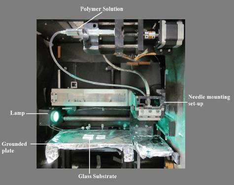 | ||
| Fig. 1 Photograph of the electrospinning setup with glass samples mounted for electrospinning. | ||
2.3 Spray coating of P-25 TiO2
The prepared P-25 solution was loaded into the pneumatic controlled spray gun and then sprayed onto the cleaned soda lime glass sample for nearly 8 min. It is ensured that the coating is uniformly distributed throughout the glass sample. The coated glass sample was then sintered at around 450 °C for 30 min with a ramping rate of 2 °C per min. The thickness of the film was measured by a surface profilometer and was found to be 2 μm. The prepared spray-coated sample is then tested for photocatalytic activity.2.4 Self-cleaning (photocatalysis) experiment
Photocatalysis, which forms the basis of the self-cleaning property of TiO2, has been performed as follows. The dye solution was prepared by dissolving 50 mg of Alizarin Red (Aldrich, Germany) powder in 50 mL of de-ionized water. The TiO2 coated glass samples were kept immersed in the dye solution for 1 h and then they were irradiated using a conventional UV lamp. The glass samples were withdrawn at different time intervals and the absorbance spectra of the samples containing Alizarin Red were measured.3. Instrumentation
The morphology of the coated glass samples were analyzed using scanning electron microscopy (SEM, Quanta 200 FEG System, FEI Company, USA, operated at 10 kV and JEOL JSM-6701F operated at 30 kV, respectively). Samples for the SEM were prepared by sputtering a platinum conducting layer onto the TiO2 coated surface of the glass sample. The sintered rice-shaped nanostructures were further examined by a high-resolution transmission electron microscope (HR-TEM, JEOL 3010 operated at 300 kV). The sample for the HR-TEM was prepared by dispersing the sintered TiO2 (the material was scratched-off from the glass plates) in methanol under sonication and then allowing a drop of this suspension to dry on a carbon-coated copper grid. The optical properties were examined by UV–Vis spectroscopy (Shimadzu UV-3600 UV–VIS–NIR spectrophotometer) with a spectral resolution of 1 nm. Water contact angle (WCA) measurements were carried out on the coated glass samples using a contact angle measurement setup (VCA optima contact angle equipment from AST Products). The thickness of the film was measured by a surface profilometer (Aplha–Step IQ Surface Profiler).4. Characterization
Fig. 2A shows the SEM image of the electrospun TiO2 coated glass surface revealing a continuous and uniform distribution of well-connected porous rice-shaped nanostructures. It is also interesting to note the absence of micro-cracks in the TiO2 film. The average dimensions of the rice grain-like structures were in the range of 150 to 300 nm in length and 100 to 200 nm in diameter. The nanostructures were highly porous due to the evaporation of polymer from the matrix which results in a high surface area of ∼60 m2 g−1.19 The TiO2 was further examined by HR-TEM. Fig. 2B shows the TEM image of a single rice-shaped structure and its microstructure. It can be seen from the image that a single TiO2 nanostructure is actually made up of numerous spherical particles of average diameter of 15–20 nm. The lattice-resolved TEM image (Fig. 2C) confirmed the anatase phase of TiO2 (d spacing = 0.35 nm). The powder XRD pattern (Fig. 2D) further confirmed the anatase phase of TiO2, however, with a negligibly small presence of rutile. The major peaks are indexed in the spectrum itself.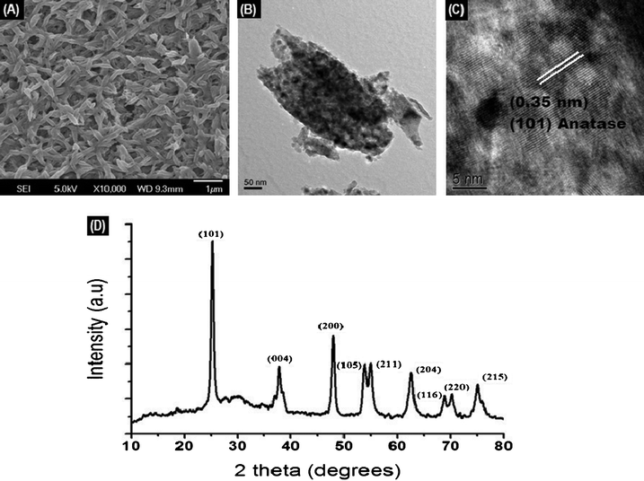 | ||
| Fig. 2 (A) SEM image of the TiO2 coated glass sample; (B) TEM image of a single nanostructure (C) the lattice-resolved image (D) XRD of the TiO2 sintered at 450 °C. | ||
5. Results and discussions
5.1 Superhydrophilicity of the TiO2 thin film
The self-cleaning effect of hydrophilic TiO2 film is well known30 and can be summarized as follows. There is a formation of a chemisorbed H2O layer on the TiO2 film due to its hydrophilic property. This chemisorbed H2O layer attracts water molecules by van der Waals forces and the hydrogen bonds that obstruct the contact between surface and adsorbed contaminants. As a result, the impurities adsorbed on the coated surface are removed by the spreading action of water and the coated TiO2 glass surface exhibits a self-cleaning effect.A series of samples with different TiO2 thicknesses on glass were prepared by varying the electrospinning time from 1 to 3 min. Thicknesses of TiO2 in the range of 96 to 220 nm were fabricated by this method. The electrospun TiO2 coated glass samples showed very good hydrophilicity (sintering of the electrospun fibers resulted in the deposition of porous, well-connected, randomly oriented and unique-shaped TiO2 network on glass) and the hydrophilicity increases and attains a state of superhydrophilicity (WCA approx. equal to 2 ± 1°) when the thickness of TiO2 reaches 220 nm (see Table 1). This is further evident from the digital photographs in Fig. 3 & Fig. 4, respectively. A plot of the decrease in WCA vs. increase in thickness of the coating is shown in Fig. 5.
 | ||
| Fig. 3 Interaction of water droplet with plain and TiO2-coated glass. (A) plain glass, (B) TiO2-coated for 1.5 min and (C) that coated for 3 min. | ||
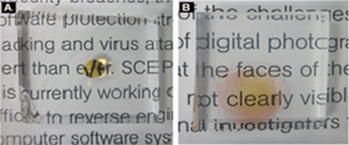 | ||
| Fig. 4 Photographs showing the interaction of Alizarin Red dye (water solution) with plain glass (A) and TiO2-coated glass sample (B). A coloured solution was used here to clearly see the water droplet. | ||
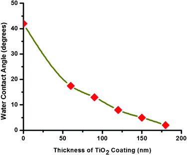 | ||
| Fig. 5 Measured decrease of WCA vs. thickness of the TiO2 coating. | ||
| Sample | Electro-spinning Time (seconds) | Thickness of the Coating (nm) | Water Contact Angle (WCA) (degrees) |
|---|---|---|---|
| 1 | Plain Glass | N/A | 42 ± 2 |
| 2 | 60 | 96 | 17.5 ± 2 |
| 3 | 90 | 129 | 13 ± 2 |
| 4 | 120 | 161 | 8 ± 2 |
| 5 | 150 | 195 | 5 ± 2 |
| 6 | 180 | 220 | 2 (± 1°) |
The increase in hydrophilicity (that is decrease of WCA) with increase in the thickness of TiO2 is caused by the increase in the density of the networked nanostructures that enables quick water chemisorption. As a water droplet is put on the surface, a small amount of the water is also quickly sucked into the inner porous layers, resulting in a decrease of WCA with increase in thickness. In accordance with Classic Wetting theory,31 the apparent contact angle θ* for any rough surface obeys Wenzel's Law,32
| Cos θ* = r Cos θ. |
In the above equation, r represents the surface roughness ratio and θ is the contact angle of a flat substrate. The roughness ratio ‘r’ is primarily a function of the coated film thickness33 and exhibits an exponential decay relationship with the film thickness (as observed from Fig. 5).
The TiO2 is completely anatase in phase28 and thus the electrospun TiO2 films would be rich in the (101) crystal lattice orientation which is a favorable condition for super-hydrophilicity owing to the rich hydroxyl density.34 It was also observed that the coated TiO2 surface showed an increase in the hydrophilic behavior when it was exposed to sunlight. This phenomenon could be due to the increase in the formation of electrons and holes. The electrons tend to reduce the Ti(IV) cations to the Ti(III) state, and the holes oxidize the O2− anions, resulting in the ejection of oxygen atoms, thereby creating oxygen vacancies. Water molecules occupy these oxygen vacancies, producing adsorbed OH groups, which tend to make the surface hydrophilic.35,36
5.2 Optical properties
A comparison of the UV–Vis spectra (in transmittance mode) of plain glass and the electrospun TiO2 coated glass sample is shown in Fig. 6. Results indicate that the transmittance of plain glass and the TiO2 coated glass were very similar (around 90%) for the entire wavelength range. This further implies that the TiO2 coating does not affect the optical properties of the glass (light transmittance), which makes this coating methodology suitable for window and solar module applications.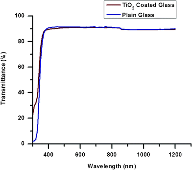 | ||
| Fig. 6 A comparison of the transmittance of plain and TiO2-coated glass samples. | ||
5.3 Photocatalysis
The phenomenon of photocatalysis has been studied intensively for many years by a number of research groups, and the mechanism is fairly well understood. As TiO2 is a semiconductor, UV light can excite electron-hole pairs. The photogenerated electrons then react with molecular oxygen (O2) to produce superoxide radical anions (.O2−), and the photogenerated holes react with water to produce hydroxyl (–OH) radicals. These two reactive radicals work together to decompose organic compounds.37 On the other hand, the –OH groups can trap more photogenerated holes and improve the separation of electrons and holes38,39 which results in the enhancement of photocatalysis.Degradation of Alizarin Red dye (AR) was used in this study to analyze the photocatalytic activity of the electrospun TiO2 coating. A TiO2 coated glass sample was kept immersed in the AR solution for 1 h and the absorption spectrum was measured. The sample was then irradiated under a UV lamp for different time intervals and the absorption spectra were measured (Fig. 7). The peak intensity at 353 nm was used to estimate the relative concentration of AR on the TiO2-coated glass sample.
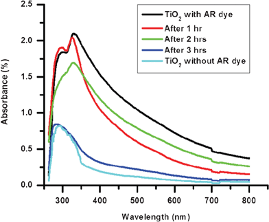 | ||
| Fig. 7 Spectral changes of the TiO2-coated glass sample with AR dye during UV catalytic degradation. | ||
It was observed from Fig. 7 that with the increase in irradiation time, the concentration of AR on the coated glass sample gradually decreases and after 3 h of UV exposure, the spectrum of the TiO2 sample with the dye almost matches the spectrum of coated sample without the dye. The rate of degradation log (C0/C) (where C0 is the initial concentration of the dye and C is the concentration at time t) of the AR dye on the TiO2 coated glass sample is plotted (Fig. 8) and the value of rate constant K was calculated using the first order rate constant equation K = 2.303 log (C0/C) and was found to be 2.7 × 10⁻³sec−1. From the results it can be concluded that the TiO2 coated glass sample exhibits good photocatalytic behavior.
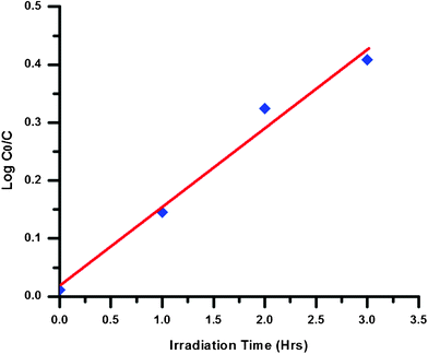 | ||
| Fig. 8 Kinetic plots and rate constant evaluation from the linear fitting using equation K = 2.303 × log(C0/C). | ||
We have also compared the photocatalytic (self-cleaning) behavior of the electrospun TiO2 film with a film fabricated from commercially available P-25 TiO2 by spray deposition. Films of 2 μm thickness were used for the study (as it was difficult to precisely achieve films with nanometre thickness by spray deposition technique). Both the glass samples with similar thickness of TiO2 were kept immersed in the AR dye solution for about 1 h (to have saturable absorption of the dye) and then irradiated under a UV lamp. The photodegradation of AR dye on both the samples was closely monitored by taking photographs at different time intervals of UV irradiation (Fig. 9). After 2 h of UV irradiation, there were no traces of AR dye on the electrospun TiO2 thin film while slight traces of AR dye were seen on the Degussa P-25 film. The enhanced photocatalytic performance of rice-grain shaped TiO2 compared to the P-25 could be attributed to highly crystalline nature and higher surface area of the former in comparison to the latter.40
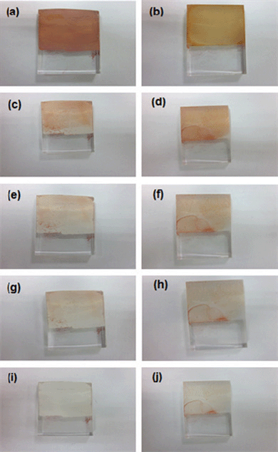 | ||
| Fig. 9 Photographs of Rice-grain shaped TiO2 (left) and P-25 (right) samples. (a & b) before UV irradiation; (c & d) after UV irradiation for 30 min; (e & f) after UV irradiation for 1 h; (g & h) after UV irradiation for 1 h and 30 min; (i & j) after UV irradiation for 2 h.). | ||
6. Conclusion
Self-cleaning TiO2 coatings comprising of rice-shaped nanostructures were fabricated on glass substrates by electrospinning. The nanostructures were characterized using SEM, TEM, XRD and spectrophotometry. The optical properties (transmittance and absorbance) and self-cleaning properties (superhydrophilicity and photocatalysis) of the coatings were studied. The results show that the superhydrophilicity of the TiO2 coated films increased with an increase in the thickness of the TiO2 due to quick water chemisorption to the inner porous layers. The coatings are transparent and do not affect the optical properties of the plain glass. The photocatalytic activity of the electrospun TiO2 and spray-coated Degussa P-25 were compared by photo-degradation of Alizarin red dye solution and it was found that the electrospun TiO2 possesses better photocatalytic activity than the P-25 due to the single crystalline nature and high surface area of the rice-shaped structures.Acknowledgements
V. A. G and H. K. R acknowledge PhD research fellowships from the National University of Singapore. A. S. N and S. R. acknowledge National Research Foundation and M3TC (EDB), Singapore for financial support (Grant No.s NRF 2007 EWT-CERP 01-0531 and R-261-501-018-414).References
- V. A. Ganesh, H. K. Raut, A. S. Nair and S. Ramakrishna, J. Mater. Chem., 2011, 21, 16304–16322 RSC.
- H. K. Raut, V. A. Ganesh, A. S. Nair and S. Ramakrishna, Energy Environ. Sci., 2011, 4, 3779–3804 CAS.
- I. P. Parkin and R. G. Palgrave, J. Mater. Chem., 2005, 15, 1689–1695 RSC.
- S. Kenig, Surf. Eng., 2009, 25, 89–92 CrossRef.
- S. Nishimoto, A. Kubo, X. Zhang, Z. Liu, N. Taneichi, T. Okui, T. Murakami, T. Komine and A. Fujishima, Appl. Surf. Sci., 2008, 254, 5891–5894 CrossRef CAS.
- K.-i. Katsumata, C. E. J. Cordonier, T. Shichi and A. Fujishima, Mater. Sci. Eng., B, 2010, 173, 267–270 CrossRef CAS.
- S. Nishimoto, A. Kubo, K. Nohara, X. Zhang, N. Taneichi, T. Okui, Z. Liu, K. Nakata, H. Sakai, T. Murakami, M. Abe, T. Komine and A. Fujishima, Appl. Surf. Sci., 2009, 255, 6221–6225 CrossRef CAS.
- K. Nakata, K. Udagawa, T. Ochiai, H. Sakai, T. Murakami, M. Abe and A. Fujishima, Mater. Chem. Phys., 2011, 126, 484–487 CrossRef CAS.
- A. Fujishima, T. N. Rao and D. A. Tryk, J. Photochem. Photobiol., C, 2000, 1, 1–21 CrossRef CAS.
- Z. Guo, W. Liu and B.-L. Su, J. Colloid Interface Sci., 2011, 353, 335–355 CrossRef CAS.
- X. Wang, B. Ding, J. Yu and M. Wang, Nano Today, 2011, 6, 510–530 CrossRef CAS.
- X. Chen and S. S. Mao, Chem. Rev., 2007, 107, 2891–2959 CrossRef CAS.
- A. Fujishima, X. Zhang and D. Tryk, Surf. Sci. Rep., 2008, 63, 515–582 CrossRef CAS.
- U. Beck, D. T. Smith, G. Reiners and S .J. Dapkunas, Thin Solid Films, 1998, 332, 164–171 CrossRef CAS.
- T. Tölke, A. Heft and A. Pfuch, Thin Solid Films, 2008, 516, 4578–4580 CrossRef.
- C. Battaglin, F. Caccavale, A. Menelle, M. Montecchi, E. Nichelatti, F. Nicoletti and P. Polato, Thin Solid Films, 1999, 351, 176–179 CrossRef CAS.
- S. H. Jeong, J. K. Kim, B. S. Kim, S. H. Shim and B. T. Lee, Vacuum, 2004, 76, 507–515 CrossRef CAS.
- S. Beiβwenger, G. Bräuer, W. Dicken and J. Szczyrbowski, Surf. Coat. Technol., 1993, 60, 624–628 CrossRef.
- Q. Xu, D. V. Wellia, M. A. Sk, K. H. Lim, J. S. Loo, D. W. Liao, R. Amal and T. T. Tan, J. Photochem. Photobiol., A, 2010, 210, 181–187 CrossRef CAS.
- C. Euvananont, C. Junin, K. Inpor, P. Limthongkul and C. Thanachayanont, Ceram. Int., 2008, 34, 1067–1071 CrossRef CAS.
- Ö. Kesmez, H. Erdem Çamurlu, E. Burunkaya and E. Arpaç, Sol. Energy Mater. Sol. Cells, 2009, 93, 1833–1839 CrossRef.
- K. L. Choy, Prog. Mater. Sci., 2003, 48, 57–170 CrossRef CAS.
- Q. P. Pham, U. Sharma and A. G. Mikos, Tissue Eng., 2006, 12, 1197–1211 CrossRef CAS.
- X. Wang, C. Drew, S.-H. Lee, K. J. Senecal, J. Kumar and L. A. Samuelson, Nano Lett., 2002, 2, 1273–1275 CrossRef CAS.
- D. Kim, A. Rothschild, B. H. Lee, D. Y. Kim, S. M. Jo and H. L. Tuller, Nano Lett., 2006, 6, 2009–2013 CrossRef.
- D. Kim, J. M. Hong, B. H. Lee, D. Y. Kim, E. K. Jeon, D. K. Choi and D. J. Yang, Appl. Phys. Lett., 2007, 91, 163109 CrossRef.
- M. Y. Song, D. K. Kim, K. J. Ihn, S. M. Jo and D. Y. Kim, Nanotechnology, 2004, 15, 1861 CrossRef CAS.
- A. S. Nair, Y. Shengyuan, Z. Peining and S. Ramakrishna, Chem. Commun., 2010, 46, 7421–7423 RSC.
- Y. Shengyuan, Z. Peining, A. S. Nair and S. Ramakrishna, J. Mater. Chem., 2011, 21, 6541–6548 RSC.
- M. Takeuchi, K. Sakamoto, G. Martra, S. Coluccia and M. Anpo, J. Phys. Chem. B, 2005, 109, 15422–15428 CrossRef CAS.
- A. W. Adamson and A. P. Gast, Physical Chemistry of Surfaces, 1997,6[th] edn (New York: Wiley) Search PubMed.
- R. N. Wenzel, Ind. Eng. Chem., 1936, 28, 988–994 CrossRef CAS.
- J.-G. Fan, X.-J. Tang and Y.-P. Zhao, Nanotechnology, 2004, 15, 501 CrossRef CAS.
- T. Watanabe, A. Nakajima, R. Wang, M. Minabe, S. Koizumi, A. Fujishima and K. Hashimoto, Thin Solid Films, 1999, 351, 260–263 CrossRef CAS.
- R. Wang, N. Sakai, A. Fujishima, T. Watanabe and K. Hashimoto, J. Phys. Chem. B, 1999, 103, 2188–2194 CrossRef CAS.
- M. Nakamura, L. Sirghi, T. Aoki and Y. Hatanaka, Surf. Sci., 2002, 507-510, 778–782 CrossRef CAS.
- G. Kaishu, Surf. Coat. Technol., 2005, 191, 155–160 CrossRef.
- D. F. Ollis, E. Pelizzetti and N. Serpone, Environ. Sci. Technol., 1991, 25, 1522–1529 CrossRef CAS.
- M. Anheden, D. Y. Goswami and G. Svedberg, J. Sol. Energy Eng., 1996, 118, 2–8 CrossRef CAS.
- Z. Peining, A. S. Nair, Y. Shengyuan and S. Ramakrishna, Mater. Res. Bull., 2011, 46, 588–595 CrossRef.
| This journal is © The Royal Society of Chemistry 2012 |
