Guided-wave liquid-crystal photonics†
D. C.
Zografopoulos
*a,
R.
Asquini
b,
E. E.
Kriezis
c,
A.
d'Alessandro
ab and
R.
Beccherelli
a
aConsiglio Nazionale delle Ricerche, Istituto per la Microelettronica e Microsistemi (CNR-IMM), Via del fosso del cavaliere, 100, 00133, Rome, Italy. E-mail: dimitrios.zografopoulos@artov.imm.cnr.it
bDipartimento di Ingegneria dell'Informazione, Elettronica e Telecomunicazioni, Sapienza Università di Roma, Via Eudossiana, 18, 00184, Rome, Italy
cDepartment of Electrical and Computer Engineering, Aristotle University of Thessaloniki, GR-54124, Thessaloniki, Greece
First published on 14th June 2012
Abstract
In this paper we review the state of the art in the field of liquid-crystal tunable guided-wave photonic devices, a unique type of fill-once, molecular-level actuated, optofluidic systems. These have recently attracted significant research interest as potential candidates for low-cost, highly functional photonic elements. We cover a full range of structures, which span from micromachined liquid-crystal on silicon devices to periodic structures and liquid-crystal infiltrated photonic crystal fibers, with focus on key-applications for photonics. Various approaches on the control of the LC molecular orientation are assessed, including electro-, thermo- and all-optical switching. Special attention is paid to practical issues regarding liquid-crystal infiltration, molecular alignment and actuation, low-power operation, as well as their integrability in chip-scale or fiber-based devices.
1 Introduction
Liquid crystals (LCs) are organic materials that exhibit a state of matter whose properties lie between those of a conventional liquid and those of a solid crystal.1 Although they are fluid, LC molecules show a certain degree of ordering, positional and/or orientational, which gives them anisotropic features in their fluido-dynamic, elastic and electromagnetic properties. These properties identify LCs as promising candidates for applications based on optofluidics, a rapidly advancing scientific field, based on the synergistic merging of the functionalities offered by optics and microfluidics towards the development of novel integrated devices for telecommunications, sensing, or lab-on-chip bioscience.2,3 For a systematic review of the rheological properties of these anisotropic non-newtonian fluids, readers are referred to the sole book in the field by Pasechnik et al.4Contrary to lyotropic materials, where transition between different LC states – termed mesophases – takes place within certain concentration ranges, LCs used in optics5 are almost exclusively thermotropic, meaning that this transition is controlled by varying the operating temperature. Thermotropic materials are characterized by elongated molecules, such as one of the most common LCs, 4-pentyl-4′-cyanobiphenyl (5CB), which is shown in Fig. 1. Depending on the material composition and temperature, various LC phases may manifest, among which the nematic one is mostly exploited in LC-based applications. The rod-like molecular shape induces a high degree of anisotropy to the electromagnetic properties of LCs, which are described by a dielectric tensor.6 This is uniaxial for nematic liquid crystals (NLCs), though in exceptional conditions biaxial nematics may also be found.7 More complex anisotropy is found for smectic8 or cholesteric phases, the latter characterized by a helical rotation of the local molecular orientation axis. In the simplest case of NLCs, the difference between its non-zero components  is called dielectric anisotropy, where
  and
and  are the dielectric tensor components along the parallel (extraordinary) and degenerate perpendicular (ordinary) orientation axis of the molecules, respectively. These components are frequency dependent. Their square root, evaluated at optical frequency, represents the extraordinary (ne) and ordinary (no) refractive indices, whose difference Δn = ne − no provides the value of optical birefringence. In the visible range, this lies typically in the 0.1–0.2 range for most common materials, although it can exceed 0.4 in some cases,9–11 reaching up to 0.7.12 It exhibits only a moderate decrease in the near infrared telecom range, well described by a three coefficient extended Cauchy equation.13 Transparency and low absorption of LC span from visible to near infrared wavelengths as well. Scattering losses scale with λ−2.39, resulting in low optical losses at wavelengths used in fiber optic systems. In addition to these favorable properties, when electric fields are applied to NLC materials, they couple to the dielectric tensor and force the optical axis to lie either parallel or perpendicular to it, depending on the sign of the dielectric anisotropy at the driving frequency, while elastic forces tend to restore the original position. Motion occurs at the molecular level, though some backflow effect does occur.14
 | ||
| Fig. 1 Chemical structure of 5CB (4-pentyl-4′-cyanobiphenyl). | ||
Therefore, NLCs behave as reorientable birefringent materials, which can be employed to change the transmission, phase, or state of polarization of light. This reorientation is the key feature of their great success as materials for programmable opto-electronic devices, although research on LC properties is also very active in other scientific fields,15 such as bio-16–19 and chemical sensing,20–23 the study of carbon24 or metal nanoparticles properties,25,26 or nano-science,27 in general. As a further example, liquid crystals may also behave as molecular scale actuators realizing micro-valves for microfluidics28 and motors for rotating objects that exceed the size of the motor molecule by a factor of 10![[thin space (1/6-em)]](https://www.rsc.org/images/entities/char_2009.gif) 000.29
000.29
Undoubtedly, the most widespread LC-based opto-electronic device is the liquid crystal display (LCD),30–32 which in all but a handful of cases,33 employs NLCs. After more than three decades of intensive scientific and technological development, LCDs dominate flat electronic display application areas, such as television, laptop or mobile phones screens etc. However, the unique electro-optic properties of NLCs also makes them suitable for many other types of photonic applications.34 These include, for example, Fabry-Pérot tunable filters,35 LC-based lasing schemes,36 various graded index lenses,37–41 shutters for a variety of applications42 and spatial light modulators (SLM)43 that perform optical functions such as (i) beam steering and optical switching among bundles of optical fibres for telecommunications,44,45 (ii) dispersion compensation46 and (iii) pulse shaping.47 Moving a step beyond free space optics, there already exist slab waveguides for continuous beam steering,48,49 which have resulted in commercial products.50
Among the numerous reviews and books in the field of liquid crystals, in this work we review LC-tunable guided-wave photonic devices, a unique type of fill-once, molecular-level actuated, optofluidic systems that instead of relying on microscopic flow as in most micro-optofluidic systems, is filled only once in the fabrication phase by a fluid. In the operation phase, molecular-level collective reorientation determines a change in the optical properties of the system. We intentionally limit its scope in waveguiding structures, which show a great degree of integrability in planar or fiber-based systems. Such LC-based components are usually envisaged for low-power reconfiguration applications, switching between different functionalities and adjustment of filter devices in photonic architectures. While in free space devices only two boundary conditions are relevant for the alignment and electro-optic behavior of LC, i.e. the top and bottom flat surfaces, separated by a few μm gap, the remaining four surfaces used for sealing are always sufficiently far away not to affect the LC alignment in the useful part of the device nor its optical performances. On the contrary, in guided-wave devices, further boundary conditions play a critical role. In most cases, coupling light in and out is a critical issue, and so is selective and complete infiltration. Hence, some approaches are common to optofluidic devices that experience macroscopic flow.
The paper's structure is organized as follows: in Section 2, LC core waveguides are discussed. These waveguides greatly resemble typical integrated micro-optofluidic channels and capillaries, where light is guided by a high refractive index core. They are fabricated by various micromachining techniques in planar technologies. Using similar fabrication technologies LC planar photonic crystal waveguiding structures can also be fabricated, which are reviewed in Section 3. An alternative approach is presented in Section 4, based on photonic crystal fibers (PCFs), intrinsically hollow structures organized as bundles of capillaries, which constitute a natural platform for LC infiltration. Finally, in Section 5 conclusions are drawn and some outlooks are provided.
2 Liquid-crystal core waveguides
Infiltrated microchannels with LCs are structures which can be effectively used in micro-optofluidic systems for various applications. The main motivation of using LCs as a waveguide core resides in the configurability of optical channels to modulate and switch photonic signals by using either electro-optic or nonlinear optical effects of LC mesophases. Several approaches were implemented to make LC waveguide-based devices by using various configurations in which LC layers are exploited for waveguide control via the electro-optic effect.51–58 A suitable design of the electrodes makes possible the exploitation of the electro-optic effect to modulate the refractive index of the LC. Various electrode geometries were proposed to create periodically modulated LC core waveguides to make efficient guided distributed Bragg reflectors with wide tuning ranges over 100 nm in the 1550 nm spectral region.59–61 In a different approach, the large optical nonlinearities were successfully implemented to create optical paths by photonic control of solitons in nematic liquid crystals.62–65 Detailed reviews on the nonlinear optics of NLCs may be found in ref. 66,67.In order to envisage more complex optofluidic microsystems, basic waveguide structures were designed, fabricated and tested on silicon. The choice of silicon, the dominant material for electronics, as the substrate is mainly due to the fact that optical functions can be efficiently coupled to electronic functions. Furthermore, it is well-known that silicon is an excellent material for micromachining and microfluidic structures. In particular, precise V-grooves, already used for accurate fiber ribbon positioning, can be fabricated with a high degree of reproducibility and reliability by following a well assessed technology. Single crystal silicon wafers are also easy to cleave or saw and the silicon native oxide is a good electrical insulator acting also as an excellent low-loss optical buffer layer. Moreover, silicon relies upon several additional merits as a substrate material, such as: (i) silicon conductivity can be engineered over a wide range, in bulk as well as locally; (ii) silicon and silicon dioxide are rigid, therefore they have a reduced sensitivity to mechanical stress; and (iii) silicon and silicon dioxide do not adsorb ions or molecules, which might modify the behavior of the LC.
In this frame, silicon micromachined structures70 were proposed as candidates to host LC, polymers and other fluidic materials to envisage integration of optical, electronic and fluidic paths and functions in the same substrate. Moreover, silicon micromachining shows additional merits for LC technology. On one hand, it can provide well-defined and smooth cells and reservoirs and avoids the use of spacers, as usually employed in standard LC glass plate cells. On the other hand, by using a conductive silicon wafer as one of the two facing electrodes, a control electric field waveform can be applied to the LC. This allows the exploitation of the rich variety of electro-optical effects of LCs. Thus, functionalities such as phase and polarization control, switching, beam steering, etc. can be implemented in integrated planar optics.
Fig. 2 shows the atomic force microscopy of a typical SiO2/Si groove obtained by using standard micromachined processes on silicon with thermally grown silica, acting as low refractive index lower cladding.68 The typical triangular shape of the groove is given by the preferential etching direction in [100] silicon substrate. The main advantage in using such a structure is related to the smoothness of the surfaces. Typical widths of the waveguides are 5–15 μm. LC on silicon waveguides (LCW) are obtained by filling the triangular shaped V-groove, covered by a borosilicate glass, with NLCs, typically the well-known commercial mixture E7, which is often used as reference material. An alignment layer, previously deposited on the inner face of the glass cover, promotes orientation of the LC molecules along the groove direction, as shown in Fig. 3.69,71
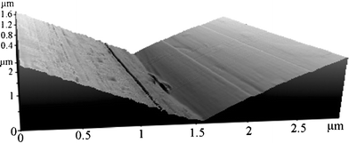 | ||
| Fig. 2 Atomic force microscope image of a silicon V-groove.68 Reprinted by permission of Taylor & Francis Ltd. | ||
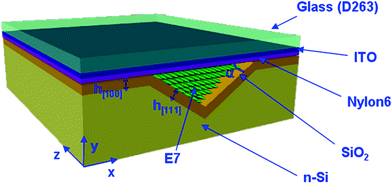 | ||
| Fig. 3 Schematic illustration of the 3D optical structure, showing the preferentially etched silicon groove, the cladding layer being the thermally grown silicon oxide and the indium tin oxide (ITO) coated borosilicate glass plate. Reprinted with permission from ref. 69, © 2010 IEEE. | ||
Fig. 4 shows how LCW is butt-coupled to a single mode optical fiber. Coupling losses mainly due to random orientation of LC molecules at input and output interfaces were reduced to about 4.5 dB when using an index matching fluid with refractive index nf = 1.5167 at the wavelength of 1550 nm and a neat LC-NOA61 interface. In this case the UV curable glue NOA61 was used in fact as polymer stopper, which provides a reduction of coupling losses by more than 10 dB.72 Propagation losses were measured to be roughly 6 dB cm−1,69 values almost one order of magnitude lower than other demonstrated LC-core optical attenuators.73
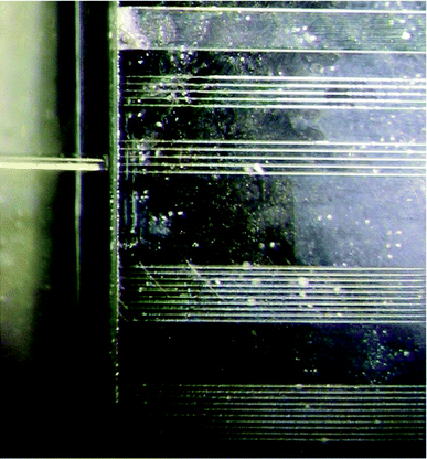 | ||
| Fig. 4 Photograph of fiber butt-coupled SiO2/Si grooves optical waveguides. Different sets of waveguides are characterized by different widths. Reprinted with permission from ref. 69, © 2010 IEEE. | ||
The LC reorientates in a few milliseconds when applying an external electric field between silicon and the upper ITO conductive layer of Fig. 3, according to LC electrostatic and elastic properties with the molecule reorientation depending on the anchoring conditions. Recently, ferroelectric liquid crystals were also proposed as switching elements, rather than waveguide core, embedded in silica on silicon channel waveguides to obtain submillisecond switching response times.74
Modeling of LCW was extensively investigated for both linear69,71,77 and nonlinear optical behaviour.75,78 Typically, waveguides with an upper width of 10 μm become multimode by increasing voltage as shown in Fig. 5. We estimated about 35 modes supported by the NLC waveguide by applying about 10 V. Modeling is based on the minimization of the free energy F = Fe + Fd, where Fe is the elastic energy and Fd the dielectric energy, which is coupled to the solution of Poisson equation for the electrostatic problem. The result is the spatial distribution of the director, the unity vector representing the average molecular orientation. The related refractive index distribution for an applied voltage of 2 V is shown in Fig. 6. The modes were then computed by using a commercial beam propagation method, which takes into account the optical anisotropy of LC with small pretilt angle with respect to the glass cover plane. Other models were also proposed to simulate optical propagation for arbitrarily oriented LC molecules.79,80
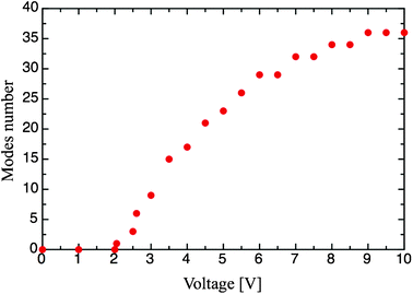 | ||
| Fig. 5 Number of modes versus applied voltage using low intensity optical power propagating in the LCW.75 | ||
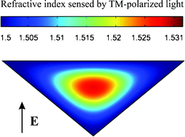 | ||
| Fig. 6 Distribution of refractive index in an NLC waveguide for an applied voltage of about 2 V, as sensed by TM-polarized light. Reprinted, with permission, from ref. 76, © 2011 IEEE. | ||
Several photonic functions can be well performed by a single LCW. They can be designed as polarizers, in which polarization extinction higher than 25 dB was measured.71Fig. 7 shows the performance of an electro-optically controlled LCW. It operates as a variable optical attenuator when applied voltage varies from 2 to 5 V and as an optical switch with extinction ratio higher than 40 dB when voltage is switched between 0 and 10 V.69
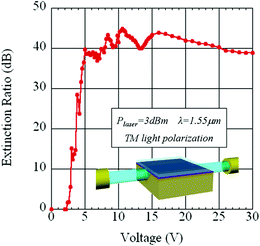 | ||
| Fig. 7 Extinction ratio vs. applied voltage of a SiO2/Si LCW. Reprinted with permission from ref. 69, © 2010 IEEE. | ||
The results of Fig. 7 demonstrate that a simple LCW without particular optimization can behave even better than similar commercially available devices. A striking feature of LCW is low power consumption mainly because of the large electro-optic effect and capacitive operation, which makes possible a wide tuning of the LC refractive index using low voltages with negligible current absorption.
LC's are well-known nonlinear optical materials, because the molecules can also be reorientated by an optical field.81 An all-optically controlled LCW was demonstrated for the first time in a channel LC waveguide in our experiments.78Fig. 8 shows the expected nonlinear behavior of an LCW as we increased the input optical power at a wavelength of 1549 nm. The nonlinear behavior was observed by applying a small bias voltage of 6.7 V for which the molecular reorientation has not saturated the optical transmission.
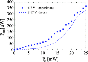 | ||
| Fig. 8 Nonlinear behavior of the NLC waveguide: comparison between experimental data and theoretical calculations. Reprinted, with permission, from ref. 76, © 2011 IEEE. | ||
For optical power higher than 20 mW the molecular reorientation does not increase the transmission any further. An extension of the model used to study the linear optical propagation of the LCW was used to describe the nonlinear variation of the optical power transmission. The minimization of free energy F = Fe + Fd was extended to the nonlinear regime by adding to the third term Fopt, which accounts for the dielectric energy associated to the optical field. The difference in voltages between theory and experiment, for which optical nonlinearity of the LC waveguide transmission was observed, are likely due in part to the presence of defects on the groove walls perturbing the LC orientation and also from the voltage drop at the electrodes not considered in the model.
Further reduction of the driving power in all-optical devices can be obtained by using doped LC mixtures. In fact, the presence of the dopant includes another effect consisting of a conformational molecular transition. In the trans state, methyl red has an elongated molecular shape, similar to that of the NLC. When exposed to green light at 532 nm in the absorption band, the methyl red molecules change shape to the isotropic cis form. The dopant role is to break the nematic phase order thus increasing the refractive index of the waveguide core. Preliminary simulations with a standard LC dopant methyl red indicate that the waveguide can be switched on by an optical signal with a power of just 5 mW.76 Furthermore, azo-dye LC mixtures can be also used to obtain faster response below microsecond regime.82
In such a field, several encapsulating materials have also been studied, polydimethylsiloxane (PDMS), SU8 and glass83 being the preferred alternative choices, which are compatible with several micro-optofluidic implementations. LCW, using such materials, are under study by some of the authors in order to design more flexible geometric paths including low loss curved optofluidic circuits.
Other promising waveguiding structures for potential optofluidic applications are POLICRYPS (POlymer LIquid CRYstal Polymer Slices),84,85 where the liquid crystal results in channels due to phase separation and acting as periodic media for Bragg gratings. Contrary to other types of LC-gratings, which are employed as free-space diffractive controllable elements,86–89 these can be used, for instance, as in-line integrated optical filters85 for sensing applications.90 A recent complete review of POLICRYPS technology is given in ref. 91. Additionally, starting from the POLICRYPS fabrication technology, it is possible to build an optically active universal template, which can be exploited for a wide range of micro-optofluidic applications relying on anisotropic materials. Once the active, soft-composite, material is introduced in the template, the quality of LC alignment, chemical interactions and confinement properties arise from a self-organization mechanism, which exploits the topology of the template to give rise to interesting, advanced photonic properties.92,93 De Sio et al.26 showed broad band tuning of the plasmonic resonance of gold nanoparticles hosted in self-organized soft materials.
3 Liquid-crystals in planar photonic crystal waveguiding structures
One of the most active research topics in the field of photonics during the past two decades has been the analysis, design and fabrication of optical components and devices based on photonic crystals (PCs).94 These periodical dielectric structures are characterized by special frequency bands, the so-called bandgaps, in which light propagation is forbidden along certain directions, depending on the periodicity of the PC. Although it has been known for a long time that one-dimensional multilayers, such as Bragg reflectors, can also be classified as PCs, modern research has been stimulated by the pioneering works of Yablonovitch95 and John96 that targeted the design of 3-D structures that exhibit a full bandgap, thus trapping or reflecting light regardless of its direction. Such complete-bandgap materials have been fabricated and characterized, an example being a PC in the IR telecom range made by silicon infiltration of an opal template of packed silica spheres.97In most cases, one of the dielectric alternating materials that form PCs of any dimensionality is air. Given this, many efforts have been thus far targeted to boost the properties of PCs by infiltrating the resulting voids with fluid materials. Isotropic liquids have been proved promising for lab-on-a chip optofluidic chemical or biomedical applications, providing extraordinary properties, an example being slow-light propagation that significantly enhances light–matter interaction.98 Going beyond isotropic fluids, which require some kind of flow to provide real tuning, the electro-optic and thermal tunability, and the large optical birefringence of LCs, suggests them as a prime candidate when it comes to the design of functional photonic crystal components.99 Infiltration of nematic LCs have been shown to be capable of tuning the bandgaps of all kinds of PCs, spanning from 1-D deeply etched silicon/LC stacks,100,101 2-D macroporous structures,102,103 or bulk-micromachined membranes104 in silicon, to 3-D opals,105–107 or holographically fabricated PCs in polymer-dispersed LCs.108 Although they allow for efficient bandgap control, such deeply etched or bulk micromachined structures cannot be easily integrated in photonic circuitry. Instead, much effort has been directed towards dielectric slab structures, based on planar silicon-on-insulator (SOI) or III/V semiconductor technologies and fabricated with deep-UV or e-beam lithography, as these structures provide adequate light confinement and guidance.
Grooved one-dimensional structures, based on etching trenches in silicon110,111 or Si3Na4112 waveguides, have been numerically investigated as a simple approach to the design of planar LC-PC electrically tunable optical filters. Nevertheless, advanced functionalities are provided by combining the properties of triangular air-hole lattices in 2-D PCs with LC-infiltration. By varying the properties or completely removing some of the air-holes, point or line defects are formed which may form resonating or waveguiding structures within the bandgaps of the surrounding PC matrix. Selective or complete infiltration of such structures with nematic LCs has been extensively numerically investigated and led to the theoretical design of numerous photonic components. LC-tunable waveguide bends and intersections have been previously proposed by Mingaleev et al.,113 as well as light-routing in infiltrated PC Y-or T-junctions.114,115 Channel add-drop filters116 and highly tunable narrow linewidth filters have been studied for WDM systems in the C + L telecom bands.117 Furthermore, various designs of directional couplers and switches, based on the electro-optical control of the LC orientation, have been analyzed.109,118,119 For instance, Fig. 9 shows the layout of a directional coupler switch based on a selectively LC-infiltrated PC with a triangular lattice. By adjusting the LC molecular orientation, the accumulated phase shift can be tuned and such a component can operate as a tunable WDM channel interleaver with sub-millimeter total length.109 In addition, LC-PCs have also been investigated in the context of other key properties for integrated photonic circuits, such as slow light for optical buffer design.120
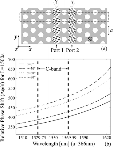 | ||
| Fig. 9 (a) Layout of a directional coupler based on a triangular 2-D PC. The waveguides are formed by selectively infiltrating two air-hole rows with a nematic LC. (b) Relative phase shift accumulated for a propagation length of 1500a for different angles γ of the nematic molecular orientation. Reprinted with permission from ref. 109. Copyright 2006, American Institute of Physics. | ||
Most of the experimental work on LC-tunable PC slabs has focused on the demonstration of controllable LC-infiltration and thermal tuning of the micro-resonances formed in III/V semiconductor PC slabs. In one of the earliest works, Schuller et al. show thermal tuning of the resonant modes in such a slab with a triangular lattice of holes infiltrated with the nematic E7.122 By varying the operating temperature the resonant wavelength shifted by 9 nm, showing larger sensitivity around the nematic to isotropic clearing temperature around 60 °C. Ferrini et al. fabricated and characterized similar PC-slab structures, which exhibit both thermal121 and all-optical tuning, the latter by doping the pure LC material 5CB, shown in Fig. 1, with 4-butyl-4-methoxyazobenzene, a dye that permits reversible photoinduced transition between nematic and isotropic states, owing to the cis–trans isomerization of its molecules.123Fig. 10 shows the transmission spectra of a PC slab infiltrated with the nematic 5CB and the thermal tuning of the TE mode supported by the slab waveguide. Excitation of the waveguide is achieved by means of two GaAsInP quantum wells buried in the slab's core layer.121 Furthermore, in a deeply-etched InP-based 2-D PC side-coupled to access waveguides, Kicken et al. thermally tuned the resonance of a point defect cavity by 7 nm.124 Finally, Baroni et al. showed a spectral shift of 13 nm of the defect mode in a free standing silicon membrane infiltrated with 5CB, close to the clearing temperature.125
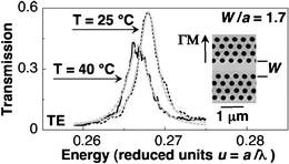 | ||
| Fig. 10 Thermal tuning of a Fabry-Pérot cavity formed in a InP-based planar PC slab infiltrated with the nematic material 5CB.121 | ||
The LC material is infiltrated, preferably in a high-vacuum chamber, to overcome issues related to surface tension and wettability and to ensure adequate control of the procedure, avoiding the formation of air bubbles.126 As the molecular orientation inside the PC holes is hard to detect directly, it can be inferred by associating the results of optical measurements with theoretical studies, assuming various configurations for the nematic director profile. Preferential alignments, both parallel122,127 and perpendicular121 to the hole axis, have been observed. The infiltration and evaporation dynamics of LC-infiltrated planar structures have also been explored in a double heterostructure cavity of a silicon PC.128 Recently, a selective infiltration technique, based on masking the PC structure and opening holes by focused ion beam (FIB) milling has been demonstrated, as shown in Fig. 11.129 The possibility to infiltrate specific holes in the PC lattice provides a great degree of freedom in the design of LC-tunable PC structures, allowing, for instance, the tuning of defect modes in the vicinity or inside the infiltrated cavities.
 | ||
| Fig. 11 (a) SEM photos showing a PC structure covered by a SiNx mask layer and a set of selectively opened holes via FIB milling for LC-infiltration. (b) A ring of six air-holes opened via the same technique.129 | ||
Although thermal control of the LC indices provides an efficient means of tuning the response of LC-PC guiding structures, full exploitation of LC tunability would require electro-optical control of the nematic molecular orientation. Even high resistivity silicon and other semiconductors relevant to photonics present conductivities several orders of magnitude higher with respect to LCs. Hence, special electrode configurations are needed in order to avoid electric field screening, since the LC sees these semiconductors as equipotential surfaces. Based on such a structure, electrical bandgap tuning has been demonstrated in free-space coupled silicon 2-D bulk micromachined suspended membrane PCs.104 Electrode integration in close proximity to the planar LC-PC slabs remains an open issue and maybe the single missing part towards the demonstration of fully functional LC-PC based components for compact, low-power light routing, filtering and manipulation in photonic crystal circuitry. While well-controlled electro-optic LC switching is still challenging in planar LC-PCs, it has long been demonstrated in the field of LC-infiltrated PC fibers, which are reviewed in the following section.
4 Liquid-crystal photonic crystal fibers
In the field of guided-wave photonics, LC-infiltrated photonic crystal fibers (PCFs) have drawn a lot of attention in the last years. PCFs constitute a special class of optical fibers characterized by a microarray of capillaries that run along the fiber's axis.130Fig. 12 shows a SEM cross-section photo of the two most known types of PCFs: solid- and hollow-core fibers, which guide light via the index- and bandgap-guiding mechanism, respectively. Apart from introducing extensive degrees of freedom in the engineering of key fiber-properties, such as large-modal area, single-mode wavelength windows, dispersion, and non-linearity, the presence of microcapillaries allows for the infiltration of the fiber with isotropic liquid or LC materials. This in turn provides extra functionalities, often unprecedented in the field of fiber optics, an example being the optofluidic transport of 3 μm fluorescent polystyrene beads in an aqueous solution infiltrating a hollow-core PCF.131 LC-boosted PCFs have been widely investigated, as they offer high optical anisotropy and broad tuning ranges, which can be exploited to dynamically control commonly, but not exclusively, the fiber's polarization properties.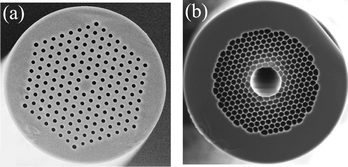 | ||
| Fig. 12 SEM photos of typical (a) solid-core, index-guiding and (b) hollow-core,132 bandgap-guiding PCFs. Fig. 12(a) reprinted, with permission, from ref. 133, © 2007 IEEE. | ||
Liquid-crystal infiltration in the PCF capillaries is usually performed via the capillary action, by simply dipping the fiber's end to a LC droplet. Vacuum or pressure application leads to higher infiltration speed and length, but may degrade alignment control and induce scattering defect points.134 Infiltration in the isotropic state has been shown to provide better alignment quality for most mixtures, such as E7,135 although others, like the dual-frequency MDA-00-3969, are more efficiently infiltrated in the nematic one.136 Typically, a filling time of tens of minutes is sufficient to infiltrate a few cm of PCF, which provides adequate optical length for almost any application.137 In some cases, special techniques are required that allow for the selective infiltration of the PCF's capillaries. Arc-fusion of the fiber's end is a simple and effective method to infiltrate the central capillary of a hollow-core PCF by collapsing the smaller ones in the cladding.138 By exploiting the difference in their infiltration velocity, selective infiltration of PCF holes with different radii has been also demonstrated.139 Finally, other techniques are also available that permit the definition of the exact pattern of the capillaries to be filled, such as direct photolithography on the PCF's cross-section,140 selective filling with a two-photon direct laser writing technique141 or the use of focused ion beam milled microchannels.142
The molecular alignment obtained during LC infiltration determines the fiber's properties in the rest state, i.e. when no external stimuli are applied. This depends mainly on the LC and glass materials, the capillary's dimensions and the anchoring conditions at the cavity's wall.148 In silica PCFs with capillary radii in the range of a few microns, most commonly used LCs show good alignment, without the need of surfactants, although these may be used for better alignment control.149,150 The type and quality of the alignment can be investigated with the aid of cross-polarizer microscopy in single silica microtubes, as shown in Fig. 13. Positive-Δε mixtures such as E7 tend to align along the capillary's axis with homogenous anchoring at the surface forming a uniform axial alignment.135 Other LCs, like MDA-00-3969, form the so-called splayed or escaped-radial alignment, where the molecules are anchored at a fixed angle at the clean silica surface and progressively align along the axis in the central part of the capillary.136 The splayed alignment offers the advantage of smoother electrically controlled transitions, without a Fréederickz-like voltage threshold and avoids the possible emergence of reverse-tilt domain defects present when axially aligned LC-infiltrated capillaries are switched.143 These properties are best exploited in the context of continuous polarization control devices; however, in polarizers or generally components where ON-OFF abrupt transitions are targeted, axially aligned LCs are, in general, more appropriate. In any case, the LC alignment quality can be further improved or controlled by applying photoalignment techniques, thus reducing scattering losses owing to orientational defects.144,151
 | ||
| Fig. 13 (a) Polarized micrograph of a 5 μm diameter silica capillary infiltrated with E7 at 45° to the polarizer axis. Uniform axial alignment along the capillary axis is observed.135 (b) Same for a capillary infiltrated with the dual-frequency MDA-00-3969, photo taken at 0/90°. The LC molecules form a splayed configuration with a 45° anchoring angle at the surface.136 (c) Defect at the interface between two reverse tilt domains in an E7-filled switched capillary. Reprinted, with permission, from ref. 143, © 2005 IEEE. (d) Improved alignment quality via the photoalignment technique in dye-doped nematic 5CB.144 A reduction of LC-induced scattering losses from 2.8 to 1.3 dB cm−1 was achieved after 10-min irradiation of the LC-PCF. | ||
As in the case of other LC-based photonic devices, the actuation of the LC molecules in LC-PCFs can take place electrically, thermally, or optically. Electrical control implies the application of a control voltage that reorientates the LC molecules via properly placed electrode pairs. Fig. 14(a) shows a proof-of-concept configuration where the fiber is placed between two parallel metal blocks/electrodes.134 This basic layout permits the demonstration of most salient features of voltage-controlled LC-PCFs however, real applications demand a higher degree of integrability. One approach involves the direct incorporation of the electrodes in the cladding during fiber-drawing,145 as shown in Fig. 14(b). Although such a configuration could possibly minimize the required voltage values, it has not been incorporated in LC-PCF devices thus far. Instead, an efficient solution for both fiber handling and electrode definition is based on the use of fiber-aligning V-grooves (Fig. 14(c)), on which the electrodes can be deposited and defined via photolithography.146,152 This technique also permits electrode patterning and the design of more complex structures, such as the periodical electrode comb147 of Fig. 14(d), which is required, for instance, in grating applications.
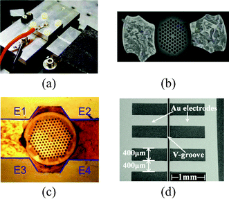 | ||
| Fig. 14 (a) Experimental setup of a LC-PCF between a pair of electrodes (photo courtesy of L. Scolari).134 (b) Integrated electrodes in the cladding of a silica PCF.145 (c) An LC-PCF placed in a V-groove assembly with four 200 nm gold deposited electrodes.146 (d) Patterning of the electrodes allows for the periodic application of the control voltage.147 | ||
Apart from the problem of electrode definition, the use of V-grooves in itself also addresses the issue of splicing between LC- and non-infiltrated PCFs, or conventional SMFs, which connect an LC-PCF device with the outer world. As arc-fusion can easily lead to LC damage, mechanical splicing is the safest way for the interconnection of LC-PCF fiber segments, with “cold” splicing with a UV-curable adhesive being a possible alternative solution.153 The employment of SU-8 fixing structures as demonstrated in Fig. 15(a) has been shown to minimize the misalignment of fiber coupling and reduce the total insertion loss of the device,154,155 whose assembly can be further strengthened by sealing with epoxy glues. Fig. 15(b) shows a fully packaged LC-PCF polarimeter in- and out-spliced to SMF fibers and wire bonded for the application of the control voltage.156
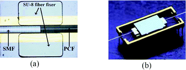 | ||
| Fig. 15 (a) Low-loss mechanical splicing between LC-PCF and SMF using SU-8 fiber fixers. Reprinted with permission from ref. 154, © 2009 IEEE. (b) A LC-PCF device pigtailed using two SMF-28 fibers and mounted in a package and wire bonded for electrical access.156 Reprinted with kind permission from Springer Science and Business Media. | ||
Although electro-optical control is most often employed, the thermal control by adjusting the fiber's temperature through resistive heating of the electrodes provides a complementary means to tune the properties of LC-PCFs. Fig. 16(a) shows the temperature dependence of the refractive indices of the commonly used mixture E7.13 The thermo-optic coefficient of both indices, between 10−4 and 10−3 RIU/°C (RIU = Refractive Index Unit), is comparable to isotropic optical liquids for temperatures away from the clearing temperature TNI. In this case, the thermo-optical tuning of LC compounds serves more as an extra degree of freedom to tune the response of the LC-PCF. Thermal tuning can be pronounced when operating close to TNI by exploiting the increased gradient dn/dT, or between different LC phases, where material properties change dramatically within a short temperature range.157 Finally, all-optical control is possible by exploiting the known cis–trans isomerization of azo-dyes, which are added in the LC mixture.158Fig. 16(b) shows the optical writing of a grating in a dye-doped LC-infiltrated capillary by exposing to blue light through a mask.159
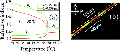 | ||
| Fig. 16 (a) Temperature dependence of the refractive indices of the nematic mixture E7.13 The nematic to isotropic temperature is 58 °C. (b) A long-period grating induced optically in a dye-doped LC- capillary.159 | ||
Despite the fact that one of the first experiments of a LC-PCF variable optical attenuator160 involved a hollow-core PCF (Fig. 12(b)), the majority of LC-PCF devices demonstrated thus far have been based on the NLC-infiltration of silica PCFs, as the one shown in Fig. 12(a). The ordinary index of typical LC materials is close to 1.5 at 1.55 μm, quite higher than the index of silica at the same wavelength (nSiO2 = 1.444). LC infiltration in the PCF's capillaries essentially forms a periodic pattern of high-index inclusions in the cladding, leading to the formation of photonic bandgap spectral windows, in which light can propagate with low losses through the solid core. When the LC is at rest case, light of either polarization (x- or y-) senses the same effective index in the holes (no), owing to the symmetry of both the axial and the splayed alignment patterns.
One of the first LC-PCF applications demonstrated was the thermal control of the fiber's bandgap edges. Thermal tuning of the high-wavelength band-edge of a silica PCF infiltrated with E7 was shown to be particularly enhanced135 when operating close to the clearing temperature of 58 °C. By using specially synthesized LC mixtures with lower TNI, an extensive band-edge tuning of 27 nm °C−1 has been shown at room temperature.161 The thermal control of the bandgap (low-) high-wavelength edge position can be directly exploited in tunable (long-) short-pass optical filtering. Moreover, by proper selection of material and fiber parameters, notch filters can also be designed. Fig. 17 shows the experimental measurements of a thermally tunable 21 nm bandwidth filter in a LC-PCF originating from the so-called avoided crossing of cladding modes within the bandgap.162 Such components can be integrated in fiber optics communication systems and provide extensive functionalities. For instance, by using an LC-PCF thermally tunable filter, Petersen et al. have shown significant improvement of optical signal quality in a transmission link using Er-doped fiber amplifiers, by amplified spontaneous emission noise filtering and gain-equalization.163
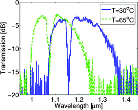 | ||
| Fig. 17 A thermally tunable notch filter in a LC-PCF showing a 21 nm, 3 dB bandwidth.162 | ||
In the presence of an applied voltage, the molecules of positive-Δε NLCs tend to align with the direction of the electric field. In the high-voltage limit, light polarized along that direction senses the extraordinary LC index, while the perpendicular polarization senses the ordinary one. In the case of silica solid-core LC-PCFs, this implies that each polarization senses a different effective periodic cladding whose bandgap positions are a function of the geometrical and material parameters, as well as the value of the applied voltage. Should the operation wavelength not coincide with a bandgap for a specific voltage, the polarization aligned with the LC molecular orientation is extinguished. Based on this principle, a series of all-fiber polarizers and polarimetric components have been demonstrated.146,154,164Fig. 18 shows the response of an all-in-fiber LC-PCF broadband polarizer, operating at 50 Vrms, which exhibits a polarization extinction ratio (PER) higher than 20 dB, with an insertion loss of 2.7 dB.154 The electrode configuration, as in Fig. 14(c), permits not only the adjustment of PER, but the steering of the polarizer axis as well, in steps of 45°.
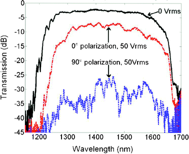 | ||
| Fig. 18 Polarization dependent electro-optic response of a 1 cm LC-PCF polarizer, showing a polarization extinction ratio higher than 20 dB. Reprinted, with permission, from ref. 154, © 2009 IEEE. | ||
Conversely, in the case where voltage-induced LC switching does not induce any kind of cut-off in the operational wavelength window, both polarizations can be guided, yet with different modal properties, exhibiting high values of modal birefringence for the bandgap-guided mode. By adjusting the set of slow- and fast-axis, modal birefringence after propagation in the LC-PCF translates to an accumulated phase shift and, potentially, polarization rotation. Based on this principle, Wei et al. fabricated LC-PCF electrically and thermally tunable quarter- and half-wave plates for rotatable polarization control in the 1520–1600 nm range.165
In addition to polarization control elements, the electrically tunable properties of bandgap-guiding LC-PCFs have also been exploited in other applications. Long-period gratings (LPGs), periodic modulations of the fiber's index that result in optical filtering at discrete Bragg resonant wavelengths, have been inscribed in LC-PCFs mechanically, electrically, and optically.147,159,166 By employing the layout shown in Fig. 14(d), Wei et al. showed electrically rewritable LPGs, which resulted in optical filtering at a thermally tunable wavelength with a PER higher than 25 dB.147 Liou et al.159 demonstrated optical LPG inscription in a LC-PCF doped with the photosensitive 4-methoxyazobenzene, using a phase mask as in Fig. 16(b). By varying the exposure time the LPG notch dip was controlled up to 20 dB, while exposure to green light erased the grating owing to trans-isomerization of the switched dye molecules. Du et al. fabricated a voltage-controlled Sagnac filter with a tuning efficiency of 0.53 nm V−1,167 while Olausson et al. combined a LC-PCF with an Yb-doped PCF in a single-mode fiber laser that showed electrically tunable lasing in the range 1040–1065 nm.168
Although silica PCFs provide the most direct choice as the fiber host for LC-infiltration, a great deal of scientific attention has been paid recently to PCFs fabricated from high-index fiberglass materials.169 These glasses contain high amounts of metal oxides, such as PbO, TeO2, and ZnO, which raise their refractive index to values higher than the indices of common NLC mixtures, up to ng = 2.2 in the case of tellurite glasses. This condition is unachievable for silica PCFs, except in the extreme case of using ultra-low ordinary index LCs inside or close to the visible spectrum.170,171 The use of a high-index glass can assure that regardless of the nematic molecular orientation profile, both polarizations are index-guided, albeit with different modal indices and propagation losses. By proper material selection, this enables broadband operation, not limited by bandgap phenomena, continuous polarization rotation control and lower losses, as the index-guided modes penetrate less in the LC-infiltrated cladding than their bandgap-guided counterparts.
These salient features were demonstrated by Ertman et al. using an LC-PCF made of a lead–bismuth–gallate glass, which showed a low-limit LC-induced loss value of ∼0.04 dB cm−1, as well as low activation and polarization dependent losses.173 In one of their recent experiments, the same group demonstrated a polarizer with a PER higher than 30 dB by selecting a glass with an index closely matching the extraordinary one of the LC.174 As the LC molecules are tilted, light polarized along their direction progressively escapes into the cladding owing to increasing confinement losses, whereas the perpendicular polarization senses always the ordinary index that provides sufficient index contrast. In a theoretical work, we demonstrated a compact electrically controlled polarization controller that permits any arbitrary polarization rotation by properly combining three segments of an index-guiding LC-PCF.172Fig. 19 shows the schematic layout of such a device and the polarization conversion from a 45° linear polarized input to a horizontal one in the output. Cross-talk values lower than 20 dB were predicted in a 30 nm window for a total device length of 4.65 mm. Light propagation studies were conducted by a fully-anisotropic beam-propagation method,175 where the LC profiles were rigorously calculated by solving for the coupled elastic/electrostatic problem.176
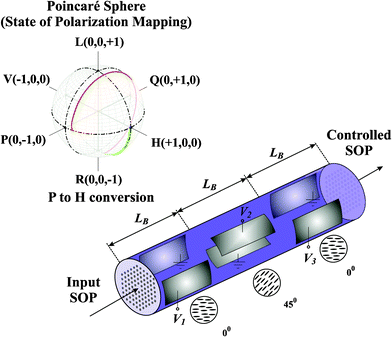 | ||
| Fig. 19 Schematic layout of a polarization controller based on an index-guiding LC-PCF. Inset shows polarization conversion of a 45° linear input polarization to a horizontal one at the exit of the device mapped on the surface of the Poincaré sphere, by properly adjusting the applied voltage in each one of three LC-PCF segments, whose length is equal to the beating length LB of the highly birefringent fiber. Reprinted with permission from ref. 172, © 2011 IEEE. | ||
The use of high-index glasses provides extra design capabilities by letting the glass index vary in a broad range. Various types of such LC-PCFs have been theoretically proposed for single-polarization and/or high-birefringence guidance or polarization splitting,177 both index-guiding, such as LC-core PCFs178,179 and bandgap-guiding in a honeycomb cladding PCF.180 A special case that is particularly interesting from both theoretical and the application point of view is the selection of the glass index between the two LC indices. When the LC molecules are tilted, light polarized along (perpendicular to) the nematic director senses a high (low) index cladding and therefore can be guided via (bandgap-) index-guiding. These hybrid-guiding LC-PCFs have been theoretically shown to combine the properties of both guiding mechanisms,181 allowing for extra control of the fiber's polarization or transmission properties.182 Recently, a variable attenuator has been demonstrated in such an LC-PCF made of Schott F2 glass.174
In almost all cases, nematic mixtures are used as the infiltrated LC material, owing to their ability to form defined molecular orientation profiles and their large degree of electrical, thermal and all-optical tunability. These can be positive- or negative-Δε,183 or even dual-frequency,136,184 which introduces another degree of freedom, the frequency of the LC-driving voltage. The latter controls the value and, most importantly, the sign of Δε that determines the reorientation axis of the LC molecules, which is parallel (perpendicular) to the applied electric field in the case of positive (negative) Δε. As an example of exploiting this property, selectively red- or blue-shifting of bandgap windows has been demonstrated.135 In the same frame, propagation losses of nematic LC-PCFs have been further reduced by using perdeuterated LC materials, which minimize absorption losses in the fiber telecom window.185 However, there is a variety of other candidate LC phases that potentially may offer richer tuning possibilities. A number of such non-nematic LC-PCFs have already been experimentally demonstrated, among which thermo-optic switches based on chiral smectic (SmA*) to chiral nematic transition (N*),157 electrically tunable notch filters in bandgap PCFs infiltrated with ferroelectric LCs,186 or thermal bandgap-tuning optical filters in chiral nematic LC-PCFs.187 In particular, FLCs may constitute an alternative to reduce the response time of NLC-PCFs, which lies in the millisecond range, as in other NLC-based photonic components. Finally, unprecedented properties may arise by enhancing known, or specially engineered, LC mixtures with nanoparticle dispersions. In a stimulating work, Scolari et al. showed a frequency modulation response arising from doping an LC-PCF with BaTiO3 nanoparticles.188
It can be naturally expected that LC-PCF based applications, such as those presented in this review, would primarily address the needs of the fiber photonic systems and networks. However, other scientific fields can also benefit from their highly functional properties. For instance, by reversing the concept of operation, LC-PCFs can be used as electric field intensity or direction sensors, with a short calibrated section playing the role of the sensor's head.189 Temperature and hydrostatic pressure sensors based on LC-PCFs have also been demonstrated.190 Further optimization of both the host PCF, including non-glass solutions, such as polymer microstructured fibers,195 and the guest LC material properties, as well as of technological issues such as LC alignment, splicing and packaging promises a whole range of unexplored possibilities. Undoubtedly, more applications based on the dynamically controlled properties of these functional fiber elements are yet to appear, as LC-PCFs strive to become a mature technology in the field of fiber optics.
5 Conclusions and outlook
Apart from already obtaining a prominent position in the displays market, thanks to their unique properties, liquid crystalline materials have managed to “infiltrate” a broad range of scientific active research fields, spanning from chemical and biomedical applications to imaging and photonic components for lasing and light manipulation. With respect to the last, this review focused on the recent developments in the field of LC-based guided wave optics for integrated photonic circuitry or fiber communication systems. Based on the mature, CMOS-compatible, liquid-crystal on silicon platform, liquid-crystal enhanced waveguides have been demonstrated, allowing for thermal, electro-optical or all-optical switching. In a complementary approach, planar photonic crystal slabs have been shown to benefit from the tunability of LC materials towards the development of ultra-compact functional components. Such low-power, highly-tunable LC-based integrated devices, either on silicon or III–V semiconductors, pave the way for functionalities in terms of light moulding, routing and filtering in chip-scale photonic circuitry. Moreover, LC-infiltration of photonic crystal fibers has been proven thus far successful in designing and fabricating numerous devices of great versatility, which provide a range of all-in-fiber solutions required by modern fiber communication and sensor systems.Nevertheless, further breakthroughs in LC-based guided-wave photonics are to be expected in the near future, certainly benefiting from the progress carried out in a number of related active research fields. Novel LC materials are synthesized in an attempt to upgrade existing solutions, such as nematic mixtures with very high birefringence, low-viscosity and low temperature operation range. Even more promising is the use of “exotic” LC compounds, among which polymerizable LCs, LCs with controllable defects for bistable devices, LCs with nanoparticle dispersions, blue phases,191 or even novel mixtures that exhibit light-induced liquid crystallinity,192 which present richer behavior and offer as yet unexplored possibilities in waveguiding devices. Progress in fabrication technologies is expected to offer improved solutions for key issues regarding LC driving, such as electrode and laser-source integration, for electro- and all-optical switching, respectively, further reducing the power budget and ameliorating the temporal response of LC-based photonic components. The development of rigorous numerical techniques for the accurate investigation of both the LC molecular orientation profiles193 and the optical properties of complex structures shall provide the toolbox for the design and optimization of end-devices such as modulators, switches, gratings and tunable filters. In parallel, other emerging technological platforms for future broadband, reduced-scale integrated circuits, such as plasmonics, can also recruit LC materials as a candidate solution in the design of functional components.194 Finally, contrary to existing solutions based on bulky capacitive or free-space optics LC devices, the optical building blocks presented in this review might also be combined with micro-actuation and chemo- or bio-detection to deliver intriguing fully integrated lab-on-a-chip microsystems that exploit the enhanced optical transduction offered by the rich dynamics and surface chemistry of LC materials. In a nutshell, more is yet to come as the evolving field of LC guided-wave photonics explores the possibilities towards novel functional devices for integrated planar and fiber optical communication and sensing systems.
Acknowledgements
This work was supported in part by the EU Marie-Curie grant ALLOPLASM (FP7-PEOPLE-2010-IEF-273528).References
- P. G. De Gennes and J. Prost, The Physics of Liquid Crystals, Clarendon Press, Oxford (UK), 2nd edn, 1993 Search PubMed.
- D. Psaltis, S. R. Quake and C. Yang, Nature, 2006, 442, 381 CrossRef CAS.
- H. Schmidt and A. R. Hawkins, Nat. Photonics, 2011, 5, 598 CrossRef CAS.
- S. V. Pasechnik, V. G. Chigrinov and D. V. Shmeliova, Liquid Crystals: Viscous and Elastic Properties in Theory and Applications, Wiley-VCH, Weinheim, Germany, 2009 Search PubMed.
- J. L. De Bougrenet De La Tocnaye, Liq. Cryst., 2004, 31, 241 CrossRef CAS.
- I.-C. Khoo, Liquid Crystals, Wiley, 2nd edn 2007 Search PubMed.
- R. Barberi, F. Ciuchi, G. Lombardo, R. Bartolino and G. E. Durand, Phys. Rev. Lett., 2004, 93, 137801 CrossRef CAS.
- V. P. Panov, J. K. Vij, N. M. Shtykov, S. S. Seomun, D. D. Parghi, M. Hird and J. Goodby, Phys. Rev. E: Stat. Phys., Plasmas, Fluids, Relat. Interdiscip. Top., 2003, 68, 021702 CrossRef CAS.
- S. Gauza, H. Wang, C.-H. Wen, S.-T. Wu, A. J. Seed and R. Dąbrowski, Jpn. J. Appl. Phys., 2003, 42, 3463 CrossRef CAS.
- H. Xianyu, S. Gauza, Q. Song and S.-T. Wu, Liq. Cryst., 2007, 34, 1473 CrossRef CAS.
- B. Bellini, M. A. Geday, N. Bennis, A. Spadło, X. Quintana, J. M. Otón and R. Dąbrowski, Opto-Electron. Rev., 2006, 14, 269 CrossRef CAS.
- Y.-M. Liao, H.-L. Chen, C.-S. Hsu, S. Gauza and S.-T. Wu, Liq. Cryst., 2007, 34, 507 CrossRef CAS.
- J. Li, S.-T. Wu, S. Brugioni, R. Meucci and S. Faetti, J. Appl. Phys., 2005, 97, 73501 CrossRef.
- D. W. Berreman, J. Appl. Phys., 1975, 46, 3746 CrossRef.
- J. P. F. Lagerwall and G. Scalia, Curr. Appl. Phys., 2012, 12, 1387 CrossRef.
- S. J. Woltman, G. D. Jay and G. P. Crawford, Nat. Mater., 2007, 6, 929 CrossRef CAS.
- I. Abdulhalim, Liq. Cryst. Today, 2011, 20, 44 CrossRef CAS.
- C.-H. Chen and K.-L. Yang, Langmuir, 2010, 26, 1427 CrossRef CAS.
- V. N. Hoang, G. V. Kaigala and C. J. Backhouse, Lab Chip, 2008, 8, 484 RSC.
- V. K. Gupta, J. J. Skaife, T. B. Dubrovsky and N. L. Abbott, Science, 1998, 279, 2077 CrossRef CAS.
- R. R. Shah and N. L. Abbott, Science, 2001, 293, 1296 CrossRef CAS.
- L. Sutarlie and K.-L. Yang, Lab Chip, 2011, 11, 4093 RSC.
- N. A. Lockwood, J. K. Gupta and N. L. Abbott, Surf. Sci. Rep., 2008, 63, 255 CrossRef CAS.
- J. P. F. Lagerwall and G. Scalia, J. Mater. Chem., 2008, 18, 2890 RSC.
- I. Dierking, G. Scalia, P. Morales and D. LeClere, Adv. Mater., 2004, 16, 865 CrossRef CAS.
- L. De Sio, R. Caputo, U. Cataldi and C. Umeton, J. Mater. Chem., 2011, 21, 18967 RSC.
- H. K. Bisoyi and S. Kumar, Chem. Soc. Rev., 2011, 40, 306 RSC.
- A. Sánchez-Ferrer, T. Fischl, M. Stubenrauch, A. Albrecht, H. Wurmus, M. Hoffmann and H. Finkelmann, Adv. Mater., 2011, 23, 4526 CrossRef.
- R. Eelkema, M. M. Pollard, J. Vicario, N. Katsonis, B. S. Ramon, C. W. M. Bastiaansen, D. J. Broer and B. L. Feringa, Nature, 2006, 440, 163 CrossRef CAS.
- H. Kawamoto, Proc. IEEE, 2002, 90, 460 CrossRef CAS.
- P. Yeh and C. Gu, Optics of Liquid Crystal Displays, Wiley, 2nd edn 2010 Search PubMed.
- E. Lüder, Liquid Crystal Displays, Wiley, 2nd edn, 2010 Search PubMed.
- Ferroelectric liquid crystal on silicon (FLCoS) microdisplays have been developed by Displaytech, (CO-USA), later acquired by Micron Technologies (http://www.micron.com/innovations/flcos.
- J. Beeckman, K. Neyts and P. J. M. Vanbrabant, Opt. Eng., 2011, 50, 081202 CrossRef.
- G. Pucker, A. Mezzetti, M. Crivellari, P. Bellutti, A. Lui, N. Daldosso and L. Pavesi, J. Appl. Phys., 2004, 95, 767 CrossRef CAS.
- A. D. Ford, S. M. Morris and H. J. Coles, Mater. Today, 2006, 9, 36 CrossRef CAS.
- S. Sato, Jpn. J. Appl. Phys., 1979, 18, 1679 CrossRef CAS.
- J. S. Patel and K. Rastani, Opt. Lett., 1991, 16, 532 CrossRef CAS.
- H. Ren, Y.-H. Fan and S.-T. Wu, Appl. Phys. Lett., 2003, 83, 1515 CrossRef CAS.
- H. Ren, D. W. Fox, B. Wu and S.-T. Wu, Opt. Express, 2007, 15, 11328 CrossRef CAS.
- P. Valley, D. L. Mathine, M. R. Dodge, J. Schwiegerling, G. Peyman and N. Peyghambarian, Opt. Lett., 2010, 35, 336 CrossRef.
- See, for instance, commercial products by AlphaMicron (OH-USA) (http://www.alphamicron.com/consumer/what_is_etint.ht).
- A. Miniewicz, A. Gniewek and J. Parka, Opt. Mater., 2002, 21, 605 CrossRef.
- W. A. Crossland, I. G. Manolis, M. M. Redmond, K. L. Tan, T. D. Wilkinson, M. J. Holmes, T. R. Parker, H. H. Chu, J. Croucher, V. A. Handerek, S. T. Warr, B. Robertson, I. G. Bonas, R. Franklin, C. Stace, H. J. White, R. A. Woolley and G. Henshall, J. Lightwave Technol., 2000, 18, 1845 CrossRef.
- P. C. Lallana, C. Vázquez, J. M. S. Pena and R. Vergaz, Opto-Electron. Rev., 2006, 14, 311 CrossRef CAS.
- M. A. F. Roelens, S. Frisken, J. A. Bolger, D. Abakoumov, G. Baxter, S. Poole and B. J. Eggleton, J. Lightwave Technol., 2008, 26, 73 CrossRef CAS.
- M. A. F. Roelens, J. A. Bolger, D. Williams and B. J. Eggleton, Opt. Express, 2008, 16, 10152 CrossRef.
- S. R. Davis, G. Farca, S. D. Rommel, A. W. Martin and M. H. Anderson, Proc. SPIE–Int. Soc. Opt. Eng., 2008, 6971, 69710G Search PubMed.
- S. R. Davis, S. D. Rommel, G. Farca and M. H. Anderson, Proc. SPIE–Int. Soc. Opt. Eng., 2008, 6975, 697503 Search PubMed.
- Vescent Photonics (CO-USA) (http://www.vescent.com/technology/liquidcrystal-waveguide-technology).
- A. d'Alessandro, R. Asquini, M. Menichella and C. Ciminelli, Mol. Cryst. Liq. Cryst., 2001, 372, 353 CAS.
- D. S. Hermann, G. Scalia, C. Pitois, F. De Marco, K. D'havé, G. Abbate, M. Lindgren and A. Hult, Opt. Eng., 2001, 40, 2188 CrossRef CAS.
- A. d'Alessandro and R. Asquini, Mol. Cryst. Liq. Cryst., 2003, 398, 207 CAS.
- G. Scalia, D. S. Hermann, G. Abbate, L. Komitov, P. Mormile, G. C. Righini and L. Sirleto, Mol. Cryst. Liq. Cryst. Sci. Technol., Sect. A, 1998, 320, 321 CrossRef CAS.
- A. d'Alessandro, R. Asquini, R. P. Bellini, D. Donisi and R. Beccherelli, Proc. SPIE–Int. Soc. Opt. Eng., 2004, 5518, 123 Search PubMed.
- K. Neyts, J. Beeckman and H. Desmet, Proc. SPIE–Int. Soc. Opt. Eng., 2007, 6487, 64870O Search PubMed.
- A. Fratalocchi, R. Asquini and G. Assanto, Opt. Express, 2005, 13, 32 CrossRef.
- R. Asquini, A. Fratalocchi, A. d'Alessandro and G. Assanto, Appl. Opt., 2005, 44, 4136 CrossRef CAS.
- D. Donisi, R. Asquini, A. d'Alessandro and G. Assanto, Opt. Express, 2009, 17, 5251 CrossRef CAS.
- G. Gilardi, R. Asquini, A. d'Alessandro and G. Assanto, Opt. Express, 2010, 18, 11524 CrossRef CAS.
- R. Asquini, G. Gilardi, A. d'Alessandro and G. Assanto, Opt. Eng., 2011, 50, 071108 CrossRef.
- G. Assanto and M. Peccianti, IEEE J. Quantum Electron., 2003, 39, 13 CrossRef CAS.
- J. F. Henninot, M. Debailleul, R. Asquini, A. d'Alessandro and M. Warenghem, J. Opt. A: Pure Appl. Opt., 2004, 6, 315 CrossRef CAS.
- J.-F. Henninot, J.-F. Blach and M. Warenghem, J. Opt. A: Pure Appl. Opt., 2007, 9, 20 CrossRef CAS.
- G. Assanto, A. Fratalocchi and M. Peccianti, Opt. Express, 2007, 15, 5248 CrossRef CAS.
- I. C. Khoo, Phys. Rep., 2009, 471, 221 CrossRef CAS.
- I. C. Khoo, J. Opt. Soc. Am. B, 2011, 28, A45 CrossRef CAS.
- R. Beccherelli, B. Bellini, D. Donisi and A. d'Alessandro, Mol. Cryst. Liq. Cryst., 2007, 465, 249 CrossRef CAS.
- D. Donisi, B. Bellini, R. Beccherelli, R. Asquini, G. Gilardi, M. Trotta and A. d'Alessandro, IEEE J. Quantum Electron., 2010, 46, 762 CrossRef CAS.
- B. Bellini, J.-F. Larchanché, J.-P. Vilcot, D. Decoster, R. Beccherelli and A. d'Alessandro, Appl. Opt., 2005, 44, 7181 CrossRef.
- A. d'Alessandro, B. Bellini, D. Donisi, R. Beccherelli and R. Asquini, IEEE J. Quantum Electron., 2006, 42, 1084 CrossRef CAS.
- B. Bellini, A. d'Alessandro and R. Beccherelli, Opt. Mater., 2007, 29, 1019 CrossRef.
- D.-P. Cai, S.-C. Nien, H.-K. Chiu, C.-C. Chen and C.-C. Lee, Opt. Express, 2011, 19, 11890 CrossRef CAS.
- X. Hu, O. Hadeler and H. J. Coles, J. Lightwave Technol., 2012, 30, 938 CrossRef CAS.
- A. d'Alessandro, R. Asquini, M. Trotta and R. Beccherelli, Proc. SPIE–Int. Soc. Opt. Eng., 2010, 7775, 777510 CrossRef.
- A. d'Alessandro, R. Asquini, M. Trotta and R. Beccherelli, 7th International Workshop on Fibre and Optical Passive Components (WFOPC), 2011,(art. no. 6089671) Search PubMed.
- B. Bellini and R. Beccherelli, J. Phys. D: Appl. Phys., 2009, 42, 045111 CrossRef.
- A. d'Alessandro, R. Asquini, M. Trotta, G. Gilardi, R. Beccherelli and I. C. Khoo, Appl. Phys. Lett., 2010, 97, 093302 Search PubMed.
- J. Beeckman, R. James, F. A. Fernández, W. De Cort, P. J. M. Vanbrabant and K. Neyts, J. Lightwave Technol., 2009, 27, 3812 CrossRef.
- C.-C. Huang, Opt. Express, 2011, 19, 3363 CrossRef CAS.
- I.-C. Khoo and S.-T. Wu, Optics and Nonlinear Optics of Liquid Crystals. Series in Nonlinear Optics, World Scientific, 1993 Search PubMed.
- N. Tabiryan, U. Hrozhyk and S. Serak, Phys. Rev. Lett., 2004, 93, 113901 CrossRef CAS.
- A. Ymeti, J. S. Kanger, J. Greve, G. A. J. Besselink, P. V. Lambeck, R. Wijn and R. G. Heideman, Biosens. Bioelectron., 2005, 20, 1417 CrossRef CAS.
- R. Caputo, L. De Sio, A. Veltri, C. Umeton and A. V. Sukhov, Opt. Lett., 2004, 29, 1261 CrossRef.
- A. d'Alessandro, D. Donisi, L. De Sio, R. Beccherelli, R. Asquini, R. Caputo and C. Umeton, Opt. Express, 2008, 16, 9254 CrossRef CAS.
- E. E. Kriezis and C. V. Brown, Liquid Crystal Diffractive Optical Elements, in Handbook of Organic Electronics and Photonics, ed. H. W. Nalwa, American Scientific Publishers (ASP), USA, 2008 Search PubMed.
- B. I. Senyuk, I. I. Smalyukh and O. D. Lavrentovitch, Opt. Lett., 2005, 30, 349 CrossRef CAS.
- H.-C. Jau, T.-H. Lin, R.-X. Fung, S.-Y. Huang, J.-H. Liu and A. Y.-G. Fuh, Opt. Express, 2010, 18, 17498 CrossRef CAS.
- H.-C. Jau, T.-H. Lin, Y.-Y. Chen, C.-W. Chen, J.-H. Liu and A. Y.-G. Fuh, Appl. Phys. Lett., 2012, 100, 131909 CrossRef.
- D. Donisi, L. De Sio, R. Beccherelli, M. A. Caponero, A. d'Alessandro and C. Umeton, Appl. Phys. Lett., 2011, 98, 151103 CrossRef.
- R. Caputo, A. De Luca, L. De Sio, L. Pezzi, G. Strangi, C. Umeton, A. Veltri, R. Asquini, A. d'Alessandro, R. B. D. Donisi, A. V. Sukhov and N. Tabiryan, J. Opt. A: Pure Appl. Opt., 2009, 11, 024017 CrossRef.
- L. De Sio, S. Ferjani, G. Strangi, C. Umeton and R. Bartolino, Soft Matter, 2011, 7, 3739 RSC.
- G. Gilardi, L. De Sio, R. Beccherelli, R. Asquini, A. d'Alessandro and C. Umeton, Opt. Lett., 2011, 36, 4755 CrossRef CAS.
- J. D. Joannopoulos, R. D. Meade and J. N. Winn, Photonic Crystals: Molding the Flow of Light, Princeton University Press, Princeton, NJ, 1995 Search PubMed.
- E. Yablonovitch, Phys. Rev. Lett., 1987, 58, 2059 CrossRef CAS.
- S. John, Phys. Rev. Lett., 1987, 58, 2486 CrossRef CAS.
- A. Blanco, E. Chomski, S. Grabtchak, M. Ibisate, S. John, S. W. Leonard, C. Lopez, F. Meseguer, H. Miguez, J. P. Mondia, G. A. Ozin, O. Toader and H. M. van Driel, Nature, 2000, 405, 437 CrossRef CAS.
- N. A. Mortensen, S. Xiao and J. Pedersen, Microfluid. Nanofluid., 2008, 4, 117 CrossRef CAS.
- H.-S. Kitzerow, A. Lorenz and H. Matthias, Phys. Status Solidi A, 2007, 11, 3754 CrossRef.
- V. A. Tolmachev, T. S. Perova, S. A. Grudinkin, V. A. Melnikov, E. V. Astrova and Yu. A. Zharova, Appl. Phys. Lett., 2007, 90, 011908 CrossRef.
- V. A. Tolmachev, T. S. Perova and E. V. Astrova, Phys. Status Solidi RRL, 2008, 2, 114 CrossRef CAS.
- S. W. Leonard, J. P. Mondia, H. M. van Driel, O. Toader, S. John, K. Busch, A. Birner, U. Gösele and V. Lehmann, Phys. Rev. B: Condens. Matter, 2000, 61, R2389 CrossRef CAS.
- G. Mertens, T. Röder, H. Matthias, H. Marsmann, H.-S. R. Kitzerow, S. L. Schweizer, C. Jamois, R. B. Wehrspohn and M. Neubert, Appl. Phys. Lett., 2003, 83, 3036 CrossRef CAS.
- M. Haurylau, S. P. Anderson, K. L. Marshall and P. M. Fauchet, Appl. Phys. Lett., 2006, 88, 061103 CrossRef.
- K. Busch and S. John, Phys. Rev. Lett., 1999, 83, 967 CrossRef CAS.
- S. John and K. Busch, J. Lightwave Technol., 1999, 17, 1931 CrossRef CAS.
- S. Gottardo, M. Burresi, F. Geobaldo, L. Pallavidino, F. Giorgis and D. S. Wiersma, Phys. Rev. E: Stat., Nonlinear, Soft Matter Phys., 2006, 74, 040702 CrossRef.
- X. H. Sun, X. M. Tao, T. J. Ye, P. Xue and Y.-S. Szeto, Appl. Phys. B: Lasers Opt., 2007, 87, 267 CrossRef CAS.
- E. P. Kosmidou, E. E. Kriezis and T. D. Tsiboukis, J. Appl. Phys., 2006, 100, 043118 CrossRef.
- D. C. Zografopoulos, E. E. Kriezis, B. Bellini and R. Beccherelli, Opt. Express, 2007, 15, 1832 CrossRef CAS.
- A. C. Tasolamprou, B. Bellini, D. C. Zografopoulos, E. E. Kriezis and R. Beccherelli, J. Eur. Opt. Soc., Rapid Publ., 2009, 4, 09017 CrossRef.
- A. D. G. Calò, M. De Sario, L. Mescia, V. Petruzzelli and F. Prudenzano, IEEE Trans. Nanotechnol., 2008, 7, 273 CrossRef.
- S. F. Mingaleev, M. Schillinger, D. Hermann and K. Busch, Opt. Lett., 2004, 29, 2858 CrossRef.
- H. Takeda and K. Yoshino, Phys. Rev. B: Condens. Matter, 2003, 67, 073106 CrossRef.
- P. Dardano, L. Moretti, V. Mocella, L. Sirleto and I. Rendina, J. Opt. A: Pure Appl. Opt., 2006, 8, S554 CrossRef CAS.
- D. M. Pustai, A. Sharkawy, S. Shi and D. W. Prather, Appl. Opt., 2002, 41, 5574 CrossRef.
- E. P. Kosmidou, E. E. Kriezis and T. D. Tsiboukis, IEEE J. Quantum Electron., 2005, 41, 657 CrossRef CAS.
- C.-Y. Liu and L.-W. Chen, IEEE Photonics Technol. Lett., 2004, 16, 1849 CrossRef.
- T. Yasuda, Y. Tsuji and M. Koshiba, IEEE Photonics Technol. Lett., 2005, 17, 55 CrossRef.
- S. Rawal, R. K. Shina and R. De La Rue, J. Lightwave Technol., 2010, 28, 2560 CrossRef CAS.
- R. Ferrini, J. Martz, L. Zuppiroli, B. Wild, V. Zabelin, L. A. Dunbar, R. Houdré, M. Mulot and S. Anand, Opt. Lett., 2006, 31, 1238 CrossRef CAS.
- C. Schuller, F. Klopf, J. P. Reithmaier, M. Kamp and A. Forchel, Appl. Phys. Lett., 2003, 82, 2767 CrossRef CAS.
- P. El-Kallassi, R. Ferrini, L. Zuppiroli, N. Le Thomas, R. Houdré, A. Barrier, S. Anand and A. Talneau, J. Opt. Soc. Am. B, 2007, 24, 2165 CrossRef CAS.
- H. H. J. E. Kicken, I. Barbu, R. W. van der Heijden, F. Karouta, R. Nötzel, E. van der Drift and H. W. M. Salemink, Opt. Lett., 2009, 34, 2207 CrossRef CAS.
- P.-Y. Baroni, Q. Tan, V. Paeder, A. Cosentino, M. Roussey, T. Scharf, H. P. Herzig and W. Nakagawa, J. Eur. Opt. Soc., Rapid Publ., 2010, 5, 10057 CrossRef.
- J. Martz, R. Ferrini, F. Nüesch, L. Zuppiroli, B. Wild, L. A. Dunbar, R. Houdré, M. Mulot and S. Anand, J. Appl. Phys., 2006, 99, 103105 CrossRef.
- C. Schuller, J. P. Reithmaier, J. Zimmermann, M. Kamp, A. Forchel and S. Anand, Appl. Phys. Lett., 2005, 87, 121105 CrossRef.
- A. C. Bedoya, S. Mahmoodian, C. Monat, S. Tomljenović-Hanić, C. Grillet, P. Domachuk, E. C. Mägi, B. J. Eggleton and R. W. van der Heijden, Opt. Express, 2010, 18, 27280 CrossRef.
- H. H. J. E. Kicken, P. F. A. Alkemade, R.W. van der Heijden, F. Karouta, R. Nötzel, E. van der Drift and H. W. M. Salemink, Opt. Express, 2009, 17, 22005 CrossRef CAS.
- P. St. J. Russell, J. Lightwave Technol., 2006, 24, 4729 CrossRef.
- S. Mandal and D. Erickson, Appl. Phys. Lett., 2007, 90, 184103 CrossRef.
- P. Russell, Opt. Photonics News, 2007, 18, 27 CrossRef.
- L. Xiao, M. S. Demokan, W. Jin, Y. Wang and C.-L. Zhao, J. Lightwave Technol., 2007, 25, 3563 CrossRef.
- L. Scolari, PhD thesis; Liquid crystals in photonic crystal fibers: fabrication, characterisation and devices, DTU Fotonik, Technical University of Denmark, 2009 Search PubMed.
- T. T. Alkeskjold, J. Lægsgaard, A. Bjarklev, D. S. Hermann, J. Broeng, J. Li and S.-T. Wu, Opt. Express, 2004, 12, 5857 CrossRef CAS.
- L. Scolari, T. T. Alkeskjold, J. Riishede, A. Bjarklev, D. S. Hermann, M. D. Nielsen and P. Bassi, Opt. Express, 2005, 13, 7483 CrossRef.
- K. Nielsen, D. Noordegraaf, T. Sørensen, A. Bjarklev and T. P. Hansen, J. Opt. A: Pure Appl. Opt., 2005, 7, L13 CrossRef CAS.
- L. Xiao, W. Jin, M. S. Demokan, H. L. Ho, Y. L. Hoo and C. Zhao, Opt. Express, 2005, 13, 9014 CrossRef.
- Y. Huang, Y. Xu and A. Yariv, Appl. Phys. Lett., 2004, 85, 5182 CrossRef CAS.
- M. Sasaki, T. Ando, S. Nogawa and K. Hane, Jpn. J. Appl. Phys., 2002, 41, 4350 CrossRef CAS.
- M. Vieweg, T. Gissibl, S. Pricking, B. T. Kuhlmey, D. C. Wu, B. J. Eggleton and H. Giessen, Opt. Express, 2010, 18, 25232 CrossRef CAS.
- F. Wang, W. Yuan, O. Hansen and O. Bang, Opt. Express, 2011, 19, 17585 CrossRef CAS.
- M. W. Haakestad, T. T. Alkeskjold, M. D. Nielsen, L. Scolari, J. Riishede, H. E. Engan and A. Bjarklev, IEEE Photonics Technol. Lett., 2005, 17, 819 CrossRef CAS.
- C.-H. Chen, C.-H. Lee and T.-H. Lin, Appl. Opt., 2010, 49, 4846 CrossRef.
- G. Chesini, C. M. B. Cordeiro, C. J. S. de Matos, M. Fokine, I. C. S. Carvalho and J. C. Knight, Opt. Express, 2009, 17, 1660 CrossRef CAS.
- T. T. Alkeskjold and A. Bjarklev, Opt. Lett., 2007, 32, 1707 CrossRef CAS.
- L. Wei, J. Weirich, T. T. Alkeskjold and A. Bjarklev, Opt. Lett., 2009, 34, 3818 CrossRef CAS.
- S. V. Burylov, J. Exp. Theor. Phys., 1997, 85, 873 CrossRef.
- A. Lorenz, H.-S. Kitzerow, A. Schwuchow, J. Kobelke and H. Bartelt, Opt. Express, 2008, 16, 19375 CrossRef CAS.
- M. S. Chychłowski, S. Ertman, E. Nowinowski-Kruszelnicki and T. R. Woliński, Mol. Cryst. Liq. Cryst., 2012, 553, 127 CrossRef.
- C.-H. Lee, C.-H. Chen, C.-L. Kao, C.-P. Yu, S.-M. Yeh, W.-H. Cheng and T.-H. Lin, Opt. Express, 2010, 18, 2814 CrossRef CAS.
- L. Wei, E. Khomtchenko, T. T. Alkeskjold and A. Bjarklev, Electron. Lett., 2009, 45, 326 CrossRef.
- T. R. Woliński, S. Ertman, D. Budadzewski, M. S. Chychłowski, A. Czapla, R. D
![[a with combining cedilla]](https://www.rsc.org/images/entities/char_0061_0327.gif) browski, A. W. Domański, P. Mergo, E. Nowinowski- Kruszelnicki, K. A. Rutkowska, M. Sierakowski and M. Tefelska, Photonics Lett. Pol., 2011, 3, 20 Search PubMed.
browski, A. W. Domański, P. Mergo, E. Nowinowski- Kruszelnicki, K. A. Rutkowska, M. Sierakowski and M. Tefelska, Photonics Lett. Pol., 2011, 3, 20 Search PubMed. - L. Wei, T. T. Alkeskjold and A. Bjarklev, IEEE Photonics Technol. Lett., 2009, 21, 1633 CrossRef CAS.
- L. Wei, W. Xue, Y. Chen, T. T. Alkeskjold and A. Bjarklev, Opt. Lett., 2009, 34, 2757 CrossRef.
- T. T. Alkeskjold, L. Scolari, D. Noordegraaf, J. Lægsgaard, J. Weirich, L. Wei, G. Tartarini, P. Bassi, S. Gauza, S.-T. Wu and A. Bjarklev, Opt. Quantum Electron., 2007, 39, 1009 CrossRef.
- T. T. Larsen, A. Bjarklev, D. S. Hermann and J. Broeng, Opt. Express, 2003, 11, 2589 CrossRef CAS.
- V. K. S. Hsiao and C.-Y. Kao, Opt. Express, 2008, 16, 12670 CrossRef CAS.
- J.-H. Liou, T.-H. Chang, T. Lin and C.-P. Yu, Opt. Express, 2011, 19, 6756 CrossRef CAS.
- F. Du, Y.-Q. Lu and S.-T. Wu, Appl. Phys. Lett., 2004, 85, 2181 CrossRef CAS.
- T. T. Alkeskjold, J. Lægsgaard, A. Bjarklev, D. S. Hermann, J. Broeng, J. Li, S. Gauza and S.-T. Wu, Appl. Opt., 2006, 45, 2261 CrossRef CAS.
- D. Noordegraaf, L. Scolari, J. Lægsgaard, T. T. Alkeskjold, G. Tartarini, E. Borelli, P. Bassi, J. Li and S.-T. Wu, Opt. Lett., 2008, 33, 986 CrossRef CAS.
- M. N. Petersen, L. Scolari, T. Tokle, T. T. Alkeskjold, S. Gauza, S.-T. Wu and A. Bjarklev, Opt. Express, 2008, 16, 20067 CrossRef CAS.
- T. R. Woliński, S. Ertman, P. Lesiak, A. W. Domański, A. Czapla, R. Dąbrowski, E. Nowinowski-Kruszelnicki and J. Wójcik, Opto-Electron. Rev., 2006, 14, 329 CrossRef.
- L. Wei, T. T. Alkeskjold and A. Bjarklev, Appl. Phys. Lett., 2010, 96, 241104 CrossRef.
- D. Noordegraaf, L. Scolari, J. Lægsgaard, L. Rindorf and T. T. Alkeskjold, Opt. Express, 2007, 15, 7901 CrossRef CAS.
- J. Du, Y. Liu, Z. Wang, B. Zou, B. Liu and X. Dong, Opt. Lett., 2008, 33, 2215 CrossRef.
- C. B. Olausson, L. Scolari, L. Wei, D. Noordegraaf, J. Weirich, T. T. Alkeskjold, K. P. Hansen and A. Bjarklev, Opt. Express, 2010, 18, 8229 CrossRef CAS.
- X. Feng, A. K. Mairaj, D. W. Hekaw and T. M. Monro, J. Lightwave Technol., 2006, 23, 2046 CrossRef.
- T. R. Woliński, K. Szaniawska, S. Ertman, P. Lesiak, A. W. Domański, R. Dąbrowski, E. Nowinowski-Kruszelnicki and J. Wójcik, Meas. Sci. Technol., 2006, 17, 985 CrossRef.
- U. A. Laudyn, K. A. Rutkowska, R. T. Rutkowski, M. A. Karpierz, T. R. Woliński and J. Wójcik, Cent. Eur. J. Phys., 2008, 6, 612 CrossRef.
- A. K. Pitilakis, D. C. Zografopoulos and E. E. Kriezis, J. Lightwave Technol., 2011, 29, 2560 CrossRef.
- S. Ertman, T. R. Woliński, D. Pysz, R. Buczyński, E. Nowinoski- Kruszelnicki and R. Dąbrowski, Opt. Express, 2009, 17, 19298 CrossRef CAS.
- S. Ertman, A. H. Rodríguez, M. M. Tefelska, M. S. Chychłowski, D. Pysz, R. Buczyński, E. Nowinoski-Kruszelnicki, R. Dąbrowski and T. R. Wolínski, J. Lightwave Technol., 2012, 30, 1208 CrossRef.
- G. D. Ziogos and E. E. Kriezis, Opt. Quantum Electron., 2008, 40, 733 CrossRef CAS.
- J. Weirich, J. Lægsgaard, L. Scolari, L. Wei, T. T. Alkeskjold and A. Bjarklev, Opt. Express, 2008, 17, 4442 CrossRef.
- M. F. O. Hameed and S. A. Obayya, IEEE Photonics J., 2009, 1, 265 CrossRef.
- D. C. Zografopoulos, E. E. Kriezis and T. D. Tsiboukis, Opt. Express, 2006, 14, 914 CrossRef CAS.
- M. F. O. Hameed and S. A. Obayya, J. Lightwave Technol., 2012, 30, 96 CrossRef.
- D. C. Zografopoulos, E. E. Kriezis and T. D. Tsiboukis, J. Lightwave Technol., 2006, 24, 3427 CrossRef CAS.
- J. Sun and C. C. Chan, J. Opt. Soc. Am. B, 2007, 24, 2640 CrossRef CAS.
- D. C. Zografopoulos and E. E. Kriezis, J. Lightwave Technol., 2009, 27, 773 CrossRef CAS.
- L. Wei, L. Eskildsen, J. Weirich, L. Scolari, T. T. Alkeskjold and A. Bjarklev, Appl. Opt., 2009, 48, 497 CrossRef.
- A. Lorentz, H.-S. Kitzerow, A. Schwuchov, J. Kobelke and H. Bartelt, Opt. Express, 2008, 23, 19375 CrossRef.
- L. Scolari, L. Wei, S. Gauza, S.-T. Wu and A. Bjarklev, Opt. Rev., 2011, 18, 114 CrossRef CAS.
- S. Mathews, Y. Semenova and G. Farrell, Electron. Lett., 2009, 45, 617 CrossRef CAS.
- M. M. Tefelska, T. R. Woliński, R. Dąbrowski and J. Wójcik, Photon. Lett. Poland, 2010, 2, 28 CAS.
- L. Scolari, S. Gauza, H. Xianyu, L. Zhai, L. Eskildsen, T. T. Alkeskjold, S.-T. Wu and A. Bjarklev, Opt. Express, 2009, 17, 3754 CrossRef CAS.
- S. Mathews, G. Farrell and Y. Semenova, IEEE Photonics Technol. Lett., 2011, 23, 408 CrossRef.
- T. R. Woliński, A. Czapla, S. Ertman, M. Tefelska, A. W. Domański, J. Wójcik, E. Nowinowski-Kruszelnicki and R. Dąbrowski, IEEE Trans. Instrum. Meas., 2008, 57, 1796 CrossRef.
- M. Ravnik, G. P. Alexander, J. M. Yeomans and S. Žumer, Proc. Natl. Acad. Sci. U. S. A., 2011, 108, 5188 CrossRef CAS.
- T. Kosa, L. Sukhomlinova, L. Su, B. Taheri, T. J. White and T. J. Bunning, Nature, 2012, 485, 347 CrossRef CAS.
- G. Lombardo, H. Ayeb and R. Barberi, Phys. Rev. E: Stat., Nonlinear, Soft Matter Phys., 2008, 77, 051708 CrossRef CAS.
- A. C. Tasolamprou, D. C. Zografopoulos and E. E. Kriezis, J. Appl. Phys., 2011, 110, 093102 CrossRef.
- W. Yuan, L. Wei, T. T. Alkeskjold, A. Bjarklev and O. Bang, Opt. Express, 2009, 17, 19356 CrossRef CAS.
Footnote |
| † Published as part of a themed issue on optofluidics |
| This journal is © The Royal Society of Chemistry 2012 |
