Combinable poly(dimethyl siloxane) capillary sensor array for single-step and multiple enzyme inhibitor assays
Yosuke
Uchiyama
,
Fumito
Okubo
,
Kozo
Akai
,
Yuji
Fujii
,
Terence G.
Henares
,
Kunio
Kawamura
,
Toshio
Yao
,
Tatsuro
Endo
and
Hideaki
Hisamoto
*
Department of Applied Chemistry, Graduate School of Engineering, Osaka Prefecture University, 1-1 Gakuen-cho, Naka-ku, Sakai City, Osaka 599-8531, Japan. E-mail: hisamoto@chem.osakafu-u.ac.jp; Fax: +81-72-254-9910; Tel: +81-72-254-9285
First published on 15th November 2011
Abstract
We describe a new method for fabricating a capillary-type sensor, called a combinable poly(dimethyl siloxane) (PDMS) capillary (CPC) sensor. The method for preparing the CPC simplifies enzyme inhibitor assays into a simple, single step assay. The sample inhibitor solution is introduced by capillary action. This triggers the spontaneous dissolution of physically adsorbed fluorescent substrates, and the substrate mixes with the inhibitor. This is followed by competitive reaction with insoluble enzyme to give a fluorescence response. CPC is composed of a convex-shaped PDMS stick containing reagents immobilized in an insoluble coating, and a concave-shaped PDMS stick containing reagents immobilized in a soluble coating. Since the concave-shaped PDMS has a deeper channel than the convex structure, combining these PDMS sticks is like closing the zipper of a “freezer bag”. This allows easy fabrication of “thin and long” capillary structures containing different reagents inside the same capillary, without the need for precise alignment. This method allows the immobilization of two reactive reagents, such as enzyme and substrate required for a single step assay, which are typically very difficult to immobilize using commercially available conventional capillaries. Furthermore, by simply arraying various CPCs, the CPC sensor allows multiple assays. Here, we carried out a single-step enzyme inhibitor assay using the CPC. In addition, two independent CPCs were arrayed to demonstrate multiple assaying of a protease inhibitor.
1. Introduction
Enzyme inhibitor assays are established methods required for various biochemical analyses during drug discovery.1 Of these assays, microplate-based fluorescence assays using synthetic substrates are widely used as they are relatively fast and quantitative.2 Thus, many assay kits are now commercially available. However, microplate-based fluorescence assays usually require premixing of reagents such as the fluorescent substrate, enzyme, and sample inhibitor.3 Furthermore, investigation of inhibitor utility for many different enzymes requires the use of many different expensive assay kits. These disadvantages have prevented fluorescence assays from contributing to their full potential to drug discovery research.To address this, various approaches using microfluidic devices have been proposed: Clausell-Tormos et al. reported a droplet-based high-throughput system;4Heet al. reported an acetylcholinesterase inhibition assay using an enzyme immobilized monolith micro-reactor;5 Garcia et al. reported a multi laminar flow-based enzyme inhibitor assay;6 Di Carlo et al. reported a high-density cell isolation array-based system;7 de Boer et al. reported a high-throughput method using capillary liquid chromatography and mass spectrometry;8 Benetton et al. reported a drug metabolism assay;9 and Hadd et al. and Xue et al. reported microchip-capillary electrophoresis-based methods.10,11 These approaches demonstrated ultrafast analysis or high-throughput analysis of enzyme inhibitors. However, the need for pressure-based or electrokinetic pumping systems has limited the adoption of these methods by non-specialist users conducting mainly routine analyses.
In contrast, we have been focusing on square glass capillary-based chemical sensors and related microfluidic devices,12–20 since this approach requires less sample/reagent and provides improved assay kinetics due to the higher surface-to-volume ratio. Chemical sensor membranes or dissolvable coatings containing fluorescent probe reagents are immobilized inside various capillaries. Introducing a sample solution by capillary action allows spontaneous reaction of the sample with the reagents, resulting in a simple, single-step analysis. However, in order to adopt this approach into a single-step enzyme inhibitor assay, immobilization of both the enzyme and the fluorescent substrate inside the same capillary is necessary. This is technically very difficult since these species react with each other during the immobilization procedure.
To solve this problem, we propose here the use of a “Combinable PDMS Capillary (CPC)” that assembles two independent PDMS structures immobilizing specific reagents into a single capillary (see Fig. 1(a)). The “concave”-shaped PDMS stick contains an immobilized dissolvable coating containing the fluorescent substrate, and the “convex”-shaped PDMS stick contains enzymes immobilized on an insoluble coating. When the sample inhibitor solution is introduced into the capillary by capillary action, the dissolvable coating disintegrates and the fluorescent substrates are released from the capillary wall and mix with the inhibitor. Then, these two species competitively react with the enzymes immobilized on an insoluble coating at the opposite side of the capillary (see Fig. 1(b)). These reactions spontaneously occur upon introduction of the sample inhibitor solution by capillary action, fully eliminating the need for complicated premixing.
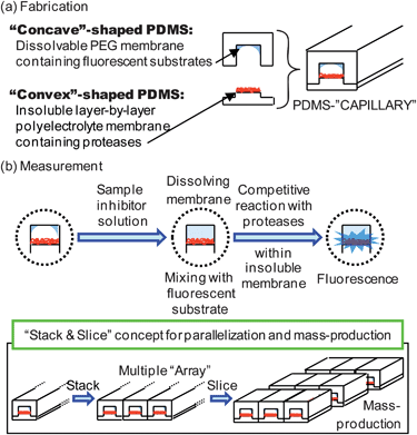 | ||
| Fig. 1 General concept for the combinable-PDMS capillary sensor array. | ||
In order to eliminate the complicated premixing, immunochromatographic paper strip immobilizing different reactive reagents is well-known and commercially available.21 However, our approach provides attractive features in mass production and multiplexation capability as illustrated in Fig. 1. This capillary-type sensor can be easily arrayed to fabricate multiplexed sensor arrays, and slicing a long capillary array into small pieces would allow mass production of multiplexed sensor arrays.
In this paper, we focused on developing a protease inhibitor assay using a CPC sensor. Proteases are intensively studied enzymes involved in various intracellular reaction cascades in many important diseases.22–25 Thus, screening various inhibitor candidates with many different proteases is of primary interest in drug discovery research. Here, we first carried out the integration of a protease inhibitor assay, and then two independent CPCs for different proteases were arrayed to demonstrate proof-of-concept for multiple assays.
2. Experimental section
2.1. Reagents
A Sylgard 184 silicone elastomer kit was purchased from Dow Corning (Midland, MI, USA). Poly(ethyleneglycol) (Mw: 20![[thin space (1/6-em)]](https://www.rsc.org/images/entities/char_2009.gif) 000) (PEG) was purchased from Wako Pure Chemical Industries (Osaka, Japan). Poly(acrylic acid, sodium salt), 35 wt% solution in water, poly(diallyl dimethylammonium chloride), low molecular weight, 20 wt% in water, poly[dimethyl siloxane-co-methyl-(3-hydroxypropyl)-siloxane]-graft-PEG methyl ether (PDMS-PEG), bovine serum albumin (BSA), trypsin from bovine pancreas, and thrombin from bovine plasma were all purchased from Sigma-Aldrich (St Louis, MO, USA). The fluorescent substrates, Boc-Gln-Ala-Arg-MCA, Boc-Asp(OBzl)-Pro-Arg-MCA, and leupeptin (trypsin inhibitor), were obtained from Peptide Institute (Osaka, Japan).
000) (PEG) was purchased from Wako Pure Chemical Industries (Osaka, Japan). Poly(acrylic acid, sodium salt), 35 wt% solution in water, poly(diallyl dimethylammonium chloride), low molecular weight, 20 wt% in water, poly[dimethyl siloxane-co-methyl-(3-hydroxypropyl)-siloxane]-graft-PEG methyl ether (PDMS-PEG), bovine serum albumin (BSA), trypsin from bovine pancreas, and thrombin from bovine plasma were all purchased from Sigma-Aldrich (St Louis, MO, USA). The fluorescent substrates, Boc-Gln-Ala-Arg-MCA, Boc-Asp(OBzl)-Pro-Arg-MCA, and leupeptin (trypsin inhibitor), were obtained from Peptide Institute (Osaka, Japan).
All reagents were used without further purification. The deionized distilled water used had resistivity values greater than 1.7 × 10⁷ Ω cm−1 at 25 °C.
2.2. Fabrication of the PDMS capillary
Convex-shaped and concave-shaped PDMS sticks were fabricated by a simple molding procedure using glass molds. For the convex-shaped PDMS stick, PDMS prepolymer was introduced into a glass mold containing a 510 μm wide and 500 μm deep channel fabricated inside the center bottom of a 2 mm wide and 3 mm deep channel. After covering the surface with a thick PDMS plate and heating for 2 hours, the convex-shaped PDMS stick was peeled off from the glass mold. For the concave-shaped PDMS stick, the PDMS prepolymer was introduced into a glass mold containing a 2 mm wide and 3 mm deep channel. In this case, a PDMS plate with a 500 μm wide and 800 μm height convex structure was used to cover the glass mold containing a 2 mm wide and 3 mm deep channel to fabricate a 500 × 800 μm channel on a PDMS stick. Each 5 cm long PDMS stick was sliced into 1 cm long pieces for individual use in measurements.The final dimensions of the capillary were approximately 500 × 300 μm.
2.3. Immobilization of coatings
2.4. Evaluation of the enzyme inhibitor assay
A convex-shaped PDMS stick with immobilized enzyme and a concave-shaped PDMS stick with immobilized fluorescent substrate were combined to form a PDMS capillary. Various concentrations of sample inhibitor solutions were introduced into the capillary by capillary action and then both sides of the capillary were sealed with a small plug of viscous PDMS to prevent evaporation. Fluorescence images were collected using a fluorescence microscope (VB-G25, Keyence, Japan) equipped with a 120 W mercury lamp as a light source and an appropriate filter pair for detecting aminomethyl coumarin (AMC), a fluorescent product formed by the enzyme reaction. Fluorescence images were converted to numerical responses using Image J software. In this case, almost all the pixels of the fluorescence image of single capillary (approximately 400 × 8000 micron) were chosen and fluorescence intensity values were averaged for use in evaluating the response.3. Results and discussion
3.1. Fabrication of CPC
Fig. 2(a) shows a cross-section of the PDMS sticks. In order to fabricate a capillary structure, concave- and convex-shaped PDMS sticks were prepared by a simple molding procedure. Actual sizes of PDMS replica were almost identical to those of glass molds used. In our case, glass molds had size errors of a few microns in width. Therefore, the solution leakage problem was anticipated. For preliminary experiments, we prepared the same widths of concave (300 μm wide, 300 μm deep) and convex (300 μm wide, 150 μm height) structures on PDMS sticks; however, significant solution leakage from the junction was observed. Furthermore, the combined CPC easily peeled from each other. Therefore, we used a slightly wider and deeper structure for the concave-shaped PDMS stick (500 μm wide, 800 μm deep) and an even wider structure for the convex-shaped PDMS stick (510 μm wide, 500 μm height) for preparing a capillary structure (500 μm wide and 300 μm deep). In this case, the concave- and convex-shaped PDMS sticks were easily combined to form a capillary-structure without solution leakage (see Fig. 2(b)). Interestingly, this capillary was also mechanically quite stable even though standard bonding procedures such as oxygen plasma treatment were not used. This may be due to the increased contact area and elastic adherence arising from the slightly wider (510 μm) convex-shaped PDMS structure.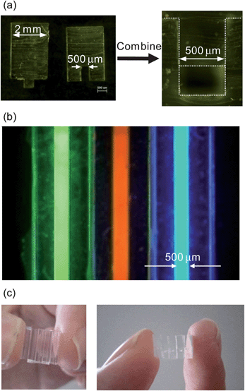 | ||
| Fig. 2 (a) Concave- and convex-shaped PDMS sticks (cross-sectional views). (b) Fluorescence image of CPC array containing different fluorescent solutions. (c) A five CPC array. | ||
Fig. 2(c) shows photographs of a CPC array (5 CPCs). The development of a single-step chemical sensing mechanism using CPC should allow development of various multiple sensing devices by simply arraying various CPCs.
3.2. Fluorescence response of CPC towards an enzyme inhibitor
A significant characteristic of the CPC sensor is the possibility of integrating complicated analytical operations such as premixing into a simple single step by immobilizing multiple analytical reagents in a single capillary structure. Here, we carried out an enzyme inhibitor assay using a “concave”-shaped PDMS stick with an immobilized PEG coating containing the fluorescent substrate and a “convex”-shaped PDMS stick with an immobilized layer-by-layer polyelectrolyte coating containing enzyme. The amount of the reagents immobilized in each coating is important to obtain reproducible results. When the PEG coating containing the fluorescent substrate was immobilized, controlling the volume of cocktail solution made it possible to keep the amount of fluorescent substrate in each “concave”-shaped PDMS stick. However, since the enzyme was immobilized by the layer-by-layer method, the amount of immobilized enzyme on each “convex”-shaped PDMS stick was experimentally unclear. Therefore, we first evaluated the reproducibility of enzyme immobilization. In this case, CPCs were prepared by using “convex”-shaped PDMS sticks immobilizing enzyme and native “concave”-shaped PDMS sticks. Then, we evaluated the fluorescence intensities by introducing fluorescent substrate solution into five independent CPCs, followed by fluorescence image analysis. Since the obtained relative standard deviation value was 5.8%, the reproducibility of the enzyme immobilization was relatively good.PDMS is generally not suitable for sample solution introduction by capillary action due to its inherent hydrophobicity. However, surface modification with PEG coating and polyelectrolyte coating increased the water wettability of PDMS. Therefore, when the sample solution droplet contacted the edge of the CPC sensor, the sample solution was spontaneously introduced by capillary action and stopped at the end of the capillary due to surface tension. Thus, sample introduction was facile and quite successful.
Fig. 3(a) shows typical fluorescence images of the CPC sensor. When a sample solution without inhibitor (buffer) was introduced into the CPC, the peptidyl-MCA fluorescent substrate was released from the capillary wall and reacted with enzyme immobilized on the opposite side of the capillary to form fluorescent products. On the other hand, when a sample solution containing the inhibitor was introduced, the enzyme reaction was inhibited so that the fluorescence response was weak. In Fig. 3(a), the obtained fluorescence intensity varied from place to place. This may be attributed to the variation of the thickness of PEG coating containing the fluorescent substrate along the longitudinal direction of the capillary, which may lead to the inhomogeneous dissolution of the fluorescent substrate, and resulted in variation of the fluorescence intensity. However, by evaluating almost all the pixels of the fluorescence image (approximately 400 × 8000 microns) and employing averaged value, the effect of inhomogeneity was reduced and reliable data were obtained. Fig. 3(b) shows typical response profiles for the CPCs when various concentrations of the inhibitor solution were introduced. As expected, both fluorescence intensity and initial reaction rate were suppressed as inhibitor concentration increased. Fig. 4 shows the inhibition curve obtained using the data shown in Fig. 3(b), and provides an IC50 value of approximately 6 × 10⁻⁶ M. Since the IC50 value for the trypsin-leupeptin system was reported to be 8 × 10⁻⁶ M,26 our CPC sensor appears quite reliable for determining IC50 values.
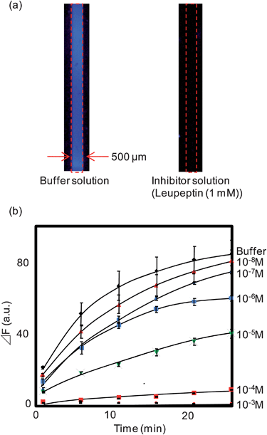 | ||
| Fig. 3 (a) Typical fluorescence images of the CPC sensor (assay time: 25 min). (b) Typical response profiles for the CPCs when the various concentrations of leupeptin solutions were introduced. Error bar represents relative standard deviation (n = 4). | ||
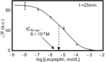 | ||
| Fig. 4 Inhibition curve obtained for the leupeptin-trypsin system. Error bar represents relative standard deviation (n = 4). | ||
In a conventional enzyme inhibitor assay, the fluorescent substrate solution containing an inhibitor is first mixed, then the enzyme solution is introduced to initiate an enzyme reaction.3 In contrast, in a CPC sensor-based assay, the inhibitor can be first contacted (reacted) with the immobilized enzyme, and then reacted with the fluorescent substrate in the second step. Since the mixing order is slightly different in the two assay methods, the effect of mixing order on the obtained IC50 value should be experimentally clarified. Therefore, we prepared a CPC sensor with immobilized enzyme but without the immobilized fluorescent substrate coating. Then, fully mixed solution containing various concentrations of the inhibitor and a constant concentration of the fluorescent substrate were introduced into the CPC and the fluorescence response was measured. The inhibition curve obtained by this method overlapped with the curve shown in Fig. 4 (data not shown), confirming good reliability of IC50 determination of trypsin by the present CPC-based assay.
3.3. Parallel assays of an inhibitor for different enzymes using the CPC array
Parallel assays of an inhibitor for different enzymes are typical and important procedures in drug screening. Using a CPC sensor, simply arraying independent CPCs for different enzymes would allow the preparation of multiple arrays. As proof of this concept, a parallel assay of leupeptin (inhibitor) to trypsin and thrombin (both protease enzymes) was carried out using a CPC array.Since the IC50 value for the trypsin-leupeptin system was reported to be 8 × 10⁻⁶ M,26 and that for the thrombin-leupeptin system to be 2.3 × 10⁻² M,27 it was expected that trypsin would be strongly inhibited and thrombin would be weakly inhibited when a leupeptin solution is introduced into CPCs for trypsin and thrombin. Fig. 5 shows the fluorescence images of a CPC array for trypsin and thrombin. When a buffer solution was introduced into the CPC array, both CPCs showed strong fluorescence responses. On the other hand, introduction of leupeptin solution into the CPC array resulted in strong inhibition of trypsin, but weak inhibition of thrombin, as expected. This result provides an example of multiple assays of a single inhibitor for different enzymes, and demonstrates that this approach could be important in the field of drug screening.
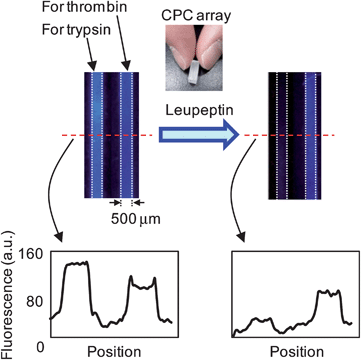 | ||
| Fig. 5 Dual assay of a single inhibitor for different enzymes by fluorescence image analysis. | ||
4. Conclusions
We have demonstrated enzyme inhibitor assays using CPCs. Earlier, our group focused on developing glass capillary sensors for ions and enzyme activities.14,15 The development of a CPC-sensor array, which incorporates two different immobilization strategies, will significantly broaden the number of multiplexed bioassays available for drug discovery and diagnosis. Since operationally the assay requires just the introduction of a sample inhibitor solution by capillary action, the present system should provide an acceptable analytical tool for non-specialists doing primarily routine bioanalyses for drug screening or diagnosis.Acknowledgements
This work was partially supported by the Tokuyama Science Foundation, a Grant-in-aid for Scientific Research from the Ministry of Education, Culture, Sports, Science and Technology of Japan (22350038), and the Funding Program for Next Generation World-Leading Researchers (LR031) from the Government of Japan.Notes and references
- G. S. Sittampalam, S. D. Kahl and W. P. Janzen, Curr. Opin. Chem. Biol., 1997, 1, 384–391 CrossRef CAS.
- C. Kohler, S. Orrenius and B. Zhivotovsky, J. Immunol. Methods, 2002, 265, 97–110 CrossRef CAS.
- Peptide (Catalog), Peptide Institute, Inc., 2011, vol. 28, pp. 167–171 Search PubMed.
- J. Clausell-Tormos, A. D. Griffiths and C. A. Merten, Lab Chip, 2010, 10, 1302–1307 RSC.
- P. He, J. Davies, G. Greenway and S. J. Haswell, Anal. Chim. Acta, 2010, 659, 9–14 CrossRef CAS.
- E. Garcia, M. S. Hasenbank, B. Finlaysonb and P. Yager, Lab Chip, 2007, 7, 249–255 RSC.
- D. Di Carlo, N. Aghdam and L. P. Lee, Anal. Chem., 2006, 78, 4925–4930 CrossRef CAS.
- A. R. de Boer, B. Bruyneel, J. G. Krabbe, H. Lingeman, W. M. A. Niessen and H. Irth, Lab Chip, 2005, 5, 1286–1292 RSC.
- S. Benetton, J. Kameoka, A. Tan, T. Wachs, H. Craighead and J. D. Henion, Anal. Chem., 2003, 75, 6430–6436 CrossRef CAS.
- A. G. Hadd, S. C. Jacobson and J. M. Ramsey, Anal. Chem., 1999, 71, 5206–5212 CrossRef CAS.
- Q. Xue, A. Wainright, S. Gangakhedkar and I. Gibbons, Electrophoresis, 2001, 22, 4000–4007 CrossRef CAS.
- H. Hisamoto, Y. Nakashima, C. Kitamura, S.-I. Funano, M. Yasuoka, K. Morishima, Y. Kikutani, T. Kitamori and S. Terabe, Anal. Chem., 2004, 76, 3222–3228 CrossRef CAS.
- H. Hisamoto, M. Yasuoka and S. Terabe, Anal. Chim. Acta, 2006, 556, 164–170 CrossRef CAS.
- T. G. Henares, M. Takaishi, N. Yoshida, S. Terabe, F. Mizutani, R. Sekizawa and H. Hisamoto, Anal. Chem., 2007, 79, 908–915 CrossRef CAS.
- T. G. Henares, F. Mizutani, R. Sekizawa and H. Hisamoto, Anal. Bioanal. Chem., 2008, 391, 2507–2512 CrossRef CAS.
- T. G. Henares, F. Mizutani, R. Sekizawa and H. Hisamoto, Anal. Sci., 2008, 24, 127–132 CrossRef CAS.
- T. G. Henares, E. Maekawa, F. Okubo, F. Mizutani, T. Yao, R. Sekizawa and H. Hisamoto, Anal. Sci., 2009, 25, 1025–1028 CrossRef CAS.
- E. Tsutsumi, T. G. Henares, K. Kawamura, T. Yao and H. Hisamoto, Chem. Lett., 2010, 39, 436–438 CrossRef CAS.
- H. Yokoyama, M. Kataoka, T. G. Henares, T. Yao and H. Hisamoto, Proc. MicroTAS, 2009, 2, 1204–1206 Search PubMed.
- M. Kataoka, H. Yokoyama, T. G. Henares, K. Kawamura, T. Yao and H. Hisamoto, Lab Chip, 2010, 10, 3341–3347 RSC.
- P. Schubert-Ullrich, J. Rudolf, P. Ansari, B. Galler, M. Führer, A. Molinelli and S. Baumgartner, Anal. Bioanal. Chem., 2009, 395, 69–81 CrossRef CAS.
- S. Kumaraswamy, T. Bergstedt, X. Shi, F. Rininsland, S. Kushon, W. Xia, K. Ley, K. Achyuthan, D. McBranch and D. Whitten, Proc. Natl. Acad. Sci. U. S. A., 2004, 101, 7511–7515 CrossRef CAS.
- T. D. Meek and G. B. Dreyer, Ann. N. Y. Acad. Sci., 1990, 616, 41–53 CrossRef CAS.
- W. C. Earnshaw, L. M. Martins and S. H. Kaufman, Annu. Rev. Biochem., 1999, 68, 383–424 CrossRef CAS.
- R. V. Talanian, K. D. Brady and V. L. Cryns, J. Med. Chem., 2000, 43, 3351–3371 CrossRef CAS.
- R. M. McConnell, J. L. York, D. Frizzell and C. Ezell, J. Med. Chem., 1993, 36, 1084–1089 CrossRef CAS.
- H. Suda, T. Aoyagi, M. Hamada, T. Takeuchi and H. Umezawa, J. Antibiot., 1972, 25, 263–265 CAS.
| This journal is © The Royal Society of Chemistry 2012 |
