Continuous flow reactors: a perspective
Charlotte
Wiles
*a and
Paul
Watts
b
aChemtrix BV, Burgemeester Lemmensstraat 358, 6163JT, Geleen, The Netherlands. E-mail: c.wiles@chemtrix.com; Tel: +44 (0)1482 466459
bThe Department of Chemistry, The University of Hull, Cottingham Road, Hull, HU6 7RX. E-mail: p.watts@hull.ac.uk; Tel: +44 (0) 1482 465471
First published on 10th November 2011
Abstract
With aspects of continuous processing featuring heavily in efforts towards increasing the ‘green’ prospects of pharmaceutical and fine chemical manufacturing, this article focuses on the developments made into the application of continuous flow reactors for sustainable chemical research and production.
Introduction
The chemical sector has long been viewed by wider society as being ‘dirty’; however, in the past two decades significant amounts of research have been conducted into the development of ‘green’ techniques for chemical synthesis, with the goal being to reduce the waste generated by the chemical industry.1In 2007, the Green Chemistry Institute (GCI), part of the American Chemical Society (ACS), set up a roundtable in conjunction with a series of global pharmaceutical companies. The roundtable listed several key areas where research was required to facilitate the development of sustainable manufacturing, the details of which can be found in a recent publication by Jiménez-González et al.2 The importance of continuous processing was acknowledged, with the panel ranking continuous processing as the primary key area for research activities.
With the pharmaceutical industry in particular still dominated by flexible batch processes and segmented unit operations, there is a lot to be learnt from the petrochemical and food industries where continuous processing features widely as a means of keeping productivity high and costs low. With these factors in mind, there has been renewed interest in the development of sustainable processes, with many of the ‘big pharma’ looking towards new techniques for both research and production.3,4 For this to be a success however, techniques are required that compliment the way that early stage researchers and process chemists work, therefore advantages associated with its use must span both disciplines; continuous flow technology has the potential to do this.
Unlike batch reactor technology, which has changed little over the past Century, continuous flow reactors form part of a rapidly growing research area which has the opportunity to change the way synthetic chemistry is performed both at a research and industrial level.5 Compared to stirred tank reactors, flow reactors have significant processing advantages including improved thermal management, mixing control and the application of extreme reaction conditions.6 Consequently, synthetic processes can be intensified by reducing the volume of solvent employed whilst maintaining control of reaction temperature.7 With this in mind, this article focuses on identifying which of the twelve principles of green chemistry, as outlined by Anastas et al.,8 have the potential to benefit from flow reactor technology (*discussed herein);
1. Prevention: It is better to prevent waste than to treat or clean up after creation.*
2. Atom economy: Synthetic methods should be designed to maximise the incorporation of all materials into the final product.*
3. Less hazardous chemical syntheses: Synthetic methods should be designed to use and generate substances that possess little or no toxicity to humans and the environment.
4. Designing safer chemicals: Chemical products should be designed to effect their desired function while minimizing their toxicity.
5. Safer solvents and auxiliaries: The use of auxiliary substances should be avoided and where necessary be innocuous.*
6. Design for energy efficiency: Energy requirements of chemical processes should be recognised for their environmental and economic impacts and should be minimised.*
7. Use of renewable feedstocks: A raw material or feedstock should be renewable whenever technically and economically practical.*
8. Reduce derivatives: Unnecessary derivatisation should be avoided because such steps can generate waste.*
9. Catalysis: Catalytic processes (as selective as possible) are superior to stoichiometric reagents.*
10. Design for degradation: Chemical products should be designed so that at the end of their function they break down into innocuous products that do not persist in the environment.
11. Real-time analysis for pollution prevention: In-process monitoring and control to minimise the formation of hazardous substances.*
12. Inherently safer chemistry for accident prevention: Substances used in a chemical process should be chosen to minimise the potential for chemical accidents, such as releases, explosions, and fires.*
Principle 1. Prevention of waste
Historically, the focus of reaction development has been on increasing the production yield of high value target compounds. More recently, due to changes in legislation and rising material costs, objectives have changed to also consider the green profile of a reaction/process.9 This can be seen in Principle 1 which focuses on the development of synthetic methods that prevent waste generation; rather than treating or cleaning-up the waste once it has been created.In the former case, the synthesis of 2-(2,5-dimethylpyrrol-1-yl)ethanol 1 was used as a model reaction, enabling Schwalbe and co-workers11 to demonstrate the ability to dramatically reduce the reaction time required for the Paal–Knorr reaction by efficiently controlling the reactor temperature. Using a stainless steel microstructured reactor, the authors were able to increase thermal control of the reaction identifying a reaction time of 5.1 min and a reactor temperature of 65 °C as being optimal for the target pyrrole 1 (91% yield); obtaining a throughput of 260 g h−1. Compared to batch, the main time saving was achieved via the ability to constantly add neat ethanolamine 2 to acetonylacetone 3 whilst controlling the reactor temperature. In the second example, Löwe and co-workers12 performed the addition of secondary amines to α,β-unsaturated compounds whereby reaction times of 17 to 25 h were typically required in order to maintain thermal control over the batch process. Utilising a micro mixer with dimensions of 40 μm (wide) × 200 μm (deep) and a tube reactor, the authors were able to access reaction times in the range of 0.8 to 5.0 ms, without the need for additional cooling; owing to the high heat transfer capacity of the microstructured device (4000 W (m2K)−1).
A niche product area that has the potential to benefit from solvent-free continuous processing is that of ionic liquid synthesis, whereby conventional synthetic procedures rely on lengthy purification steps in order to access these solvents in sufficient purities. Batch techniques are limited due to the rapid and exothermic nature of the reactions, which give rise to impurities-characterised by a yellow colouration. Renken et al.13 investigated the use of a microstructured reactor as a means of increasing reaction control and product purity. Using the synthesis of [EMIM][EtSO4] as a model reaction, the authors investigated the solvent-free alkylation under flow conditions. Using a catepillar static mixer, the authors were able to increase the production efficiency by three orders of magnitude obtaining the ionic liquid at a throughput of 0.5 kg h−1.
Employing a polysilane-supported palladium/alumina hybrid catalyst, Kobayashi and co-workers14 recently reported the development of a gas-liquid-solid reactor suitable for the hydrogenation of unsaturated C–C bonds 4 and deprotection of carbobenzyloxy functional groups under solvent-free conditions. Using this approach, the authors were able to perform selective hydrogenations without the need for dilute substrate concentrations, affording high turnover numbers (8700) and no Pd-leaching (ICP-MS analysis) (Scheme 2). In the case of solid substrates, small quantities of solvent were required however substrate concentrations in the range of 0.33 to 1.0 M were typically employed.
When considering the removal of a reaction solvent for use under flow conditions, it is essential that the reactants and products remain in the liquid phase, under the processing conditions employed, otherwise fouling of the reactor will result. It is for this reason that continuous flow reactions are more often performed at higher concentrations than their batch counterparts, but few allow the complete exclusion of solvent. To overcome this issue, additional research is required into improving post reaction separation of solvents in order to further develop solvent recyclers for use with continuous flow reactors.
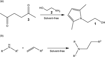 | ||
| Scheme 1 Illustration of solvent-free reactions performed under continuous flow conditions. | ||
 | ||
| Scheme 2 Hydrogenation of ethylcinnamate 4 under solvent-free conditions. | ||
Using a borosilicate glass micro reactor (Channel dimensions = 120 μm (wide) × 55 μm (deep) × 0.26 or 13.20 cm (long); Volume = 0.14 or 7.02 μl) the authors were able to conduct a detailed optimisation study which enabled a 32 s mixing time and a reaction temperature of 70 °C to be identified as being the best conditions for obtaining the target compound whilst minimising competing side reactions. By employing a flow reactor, many more reaction conditions could be evaluated than would be practical in batch whilst having the added advantage that minimal reagent volumes are consumed and higher reactor temperatures can be readily evaluated. Once identified, the optimised reaction conditions were used to produce the oxidation product, which was obtained in 96% yield.
In the same year, Buchwald and Jensen16 reported the combination of micro reactors and feedback control for the development of a self-optimising platform. Using the Heck reaction as a model, the authors were able to rapidly optimise the process using minimal quantities of reagent and then scale those optimised conditions by a factor of fifty to produce the coupling product in comparable yield. The ability to tune a reaction using small quantities of reactants therefore not only minimises the waste generated during early stage reaction screening, but also has the potential to simplify downstream processing and hence decrease the volume of waste generated at the clean-up step(s). Further waste prevention can also come about through the use of catalysts in place of stoichiometric reagents, for examples of the use of catalysts under flow, please refer to Principle 9.
Principle 2. Atom economy
The atom economy of a reaction is a measure of the percentage of the mass of reactants that are incorporated into the product and is often used as a measure of waste generation.17 Whilst this approach describes the theoretical economy of a synthetic route, reactions can still be low yielding and require purification to isolate the target compound. When looking towards continuous flow reactors, researchers have shown that by stringently controlling reaction conditions, the purity profile of reaction products can be improved, therefore reducing the complexity of subsequent purification steps or even removing the need for them altogether. Focussing on those reactions conventionally termed atom economic, the following section describes the additional synthetic advantages that can be accessed by their performance under flow conditions.Examining the synthesis of 2-allylphenol 5 from allyl phenyl ether 6 (Scheme 3), the authors employed toluene as the reaction solvent and examined the effect of reactor temperature and pressure on the reaction. Focussing on the use of a stainless steel reactor (volume = 4 ml), the authors identified that a reactor temperature of 240 °C and system pressure of 100 bar afforded the target phenol 5 in 95% yield, with a reaction time of 4 min. Using inductive heating, Kirschning et al.19 have also demonstrated the Claisen re-arrangement where increases in product yield (∼23%) were obtained when utilising a flow reactor.
 | ||
| Scheme 3 Illustration of a Claisen re-arrangement reaction performed under high temperature and pressure flow conditions. | ||
Exploiting the ability to access extreme combinations of temperature and pressure, researchers at Lilly also demonstrated the use of a re-arrangement reaction as a key synthetic step in the preparation of a thiol required for an early stage development project.20 Employing a Newman-Kwart re-arrangement (Scheme 4), the authors were able to screen the effect of temperature (250–320 °C) on the reaction, reporting the conversion of O-thiocarbamate 7 to the respective S-thiocarbamate 8 in high yield and purity. Optimal thermal conditions were found to be 300 °C, affording the target product 8 in 99.1% conversion and 93% isolated yield after recrystallisation.
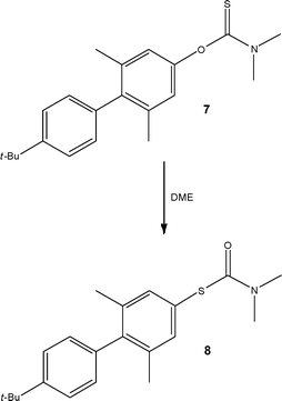 | ||
| Scheme 4 Conversion of an O-thiocarbamate 7 to an S-thiocarbamate 8 under high temperature flow conditions. | ||
 | ||
| Scheme 5 A Diels–Alder reaction performed under flow conditions within a MFD reactor. | ||
Using a chiral organocatalyst 12, Odedra and Seeberger24 reported the performance of the Mannich reaction in a glass micro reactor. Employing DMSO as the reaction solvent, the reaction of α-iminoglyoxylate 13 and cyclohexanone 14 was investigated to afford β-aminoketone 15 (Scheme 6). Using 5 mol% of catalyst 12 and a reactor temperature of 60 °C, the authors obtained the target compound in 91% yield (>95% de).
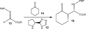 | ||
| Scheme 6 Continuous flow Mannich reaction performed using an organocatalyst 12. | ||
Looking to capitalise on the growing synthetic interest in the synthesis of substituted tetrazoles from medicinal, coordination and materials chemists, Roberge and Kappe25 recently disclosed details of a continuous flow process for the atom efficient synthesis of tetrazoles. Using the addition of hydrazoic acid to organic nitriles, the authors were able to exploit the increased process safety associated with flow reactors to efficiently synthesise a series of 5-substituted 1H-tetrazoles (Scheme 7).
 | ||
| Scheme 7 General schematic illustrating the conditions used for the continuous synthesis of 5-substituted 1H-tetrazoles. | ||
Employing a two feed Sulfinert tube reactor, the authors reacted a solution of nitrile in NMP/AcOH with a solution of aqueous sodium azide (2.5 eq.). Heating the system to 220 °C, the authors were able to safely generate HN3in situ, obtaining the target tetrazoles in isolated yields ranging from 75 to 98% with reaction times of 5 to 15 min. Compared to analogous batch reactions, the authors comment that flow reactors provide a significantly safer method for the large scale synthesis of tetrazoles as the liquid filled reactor has no headspace. In one example, 18.9 g of a tetrazole (89% yield) was synthesised in a 1 h continuous experiment. The authors have subsequently utilised a flow reactor to investigate the decomposition of 5-benzhydryl-1H-tetrazole to diphenylmethane, employing a reaction temperature of 220 °C and a residence time of 10 min.26 Jensen and Zaborenko27 concurrently reported the use of a silicon micro mixer (volume = 4.1 μl) for the two-step synthesis of the highly energetic sodium nitrotetrazole, gaining access to the material at an impressive throughput of 4.4 g h−1.
Improved atom economy has also been demonstrated for polymer synthesis in flow. Using a process of reversible addition-fragmentation chain transfer, Hornung and co-workers28 demonstrated the ability to perform the controlled radical polymerisation of a series of monomers including n-isopropylacrylamide and n-butyl acrylate. Performing the reactions under flow conditions, the authors were able to obtain narrow molecular weight distributions, when compared to batch techniques, representing a more efficient incorporation of precursors into the target products. To obtain high conversions (80–100%), the authors found it necessary to minimise the proportion of oxygen in the solvent system and reactor, thus preventing quenching of the radicals generated. The reaction sensitivity to O2 was also highlighted when a gas permeable PFA tube reactor was compared with a steel system, resulting in significantly lower product conversions.
Forming part of a continuous strategy for the synthesis of (±)-fluoxetine 16 Sanderson and Ahmed-Omer29 reported the development of an enantioselective reduction, used for the preparation of a key (S)-alcohol 17 (Scheme 8). Employing Corey–Bakshi–Shibata conditions, the authors investigated the reduction of ketone 18 with borane-N,N-diethylaniline 19 in the presence of a chiral oxazaborolidine catalyst 20. Performing the reaction at 0.24–0.40 M, no reaction was observed; however, increasing the concentration to 0.70 M resulted in quantitative reduction to afford (S)-3-chloro-1-phenyl-propanol 17 in 72% ee. Reducing the reactor temperature to −7 °C afforded the desired increase in ee, delivering the alcohol 17 in 88% yield and 92% ee. The alcohol 17 was subsequently converted to the iodo derivative in batch, followed by amination under biphasic flow conditions. The final step, a Mitsunobu reaction, enabled the nucleophilic substitution of alcohol 17 with 4-hydroxybenzotrifluoride to afford (±)-fluoxetine 16; at a throughput of 4.8 mmol h−1.
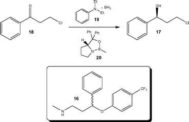 | ||
| Scheme 8 Enantioselective synthesis of a secondary alcohol 17 used in the synthesis of (±)-fluoxetine 16. | ||
To further increase the efficiency of asymmetric syntheses, Moberg and co-workers30 developed a solid-supported Lewis acid catalyst, affording a means of efficiently recycling the catalyst and simultaneously simplifying the post reaction processing required to isolate the target compounds. Using the enantioselective synthesis of TMS-cyanohydrins (Scheme 9), the authors evaluated the Lanthanide-Pybox catalyst 21 illustrating ease of reaction screening compared to batch techniques.
 | ||
| Scheme 9 Use of a solid-supported catalyst 21 for the enantioselective synthesis of TMS-cyanohydrins. | ||
Hodge et al.31 demonstrated the use of a polymer-supported cinchonidine derivative 22 (Fig. 1) and evaluated it towards the enantioselective Michael addition depicted in Scheme 10. Employing a glass tubular reactor containing 15 g of PS-cinchonidine 22, the authors investigated the addition reaction between 1-oxoindan-2-carboxylate 23 and methyl vinyl ketone 24 to afford the Michael adduct as the (S)-enantiomer 25. Using 1.06 eq. of MVK 24 and toluene as the reaction solvent the reaction mixture was pumped through the reactor which was maintained at 50 °C. Under the aforementioned conditions, the authors obtained the Michael adduct in 97% yield and 52% ee at a throughput of 10 g day−1, using a simple reaction set-up.
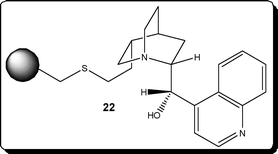 | ||
| Fig. 1 Polymer-supported cinchonidine derivative 22 shown to promote enantioselective addition reactions. | ||
 | ||
| Scheme 10 Illustration of a polymer-supported cinchonidine derivative 22 used to promote the enantioselective Michael addition in a packed-bed reactor. | ||
Principle 5. Safer solvents and auxilliaries
When looking to improve the environmental performance of a chemical process, solvents play a large role in the defining process costs and safety; consequently, the use and definition of ‘green solvents’ has attracted significant interest.32Employing a biphasic solvent system comprising of co-flowing perfluoromethylcyclohexane/toluene, Mikami et al.33 demonstrated the ability to readily recycle a Lewis acid catalyst for use in the aldol reaction. As Scheme 11 illustrates, the model reaction involved the reaction of a silyl derivative 26 and aldehyde 27 (2![[thin space (1/6-em)]](https://www.rsc.org/images/entities/char_2009.gif) :
:![[thin space (1/6-em)]](https://www.rsc.org/images/entities/char_2009.gif) 1) in the presence of scandium bis(perfluorooctane-sulfonyl)amide 28 (0.06 mol%); with quantification performed offline using GC-FID analysis of the toluene phase. Applying a reaction time of 10.8 s, the authors obtained 92% conversion of the silyl enol ether 26 (1.5
1) in the presence of scandium bis(perfluorooctane-sulfonyl)amide 28 (0.06 mol%); with quantification performed offline using GC-FID analysis of the toluene phase. Applying a reaction time of 10.8 s, the authors obtained 92% conversion of the silyl enol ether 26 (1.5![[thin space (1/6-em)]](https://www.rsc.org/images/entities/char_2009.gif) :
:![[thin space (1/6-em)]](https://www.rsc.org/images/entities/char_2009.gif) 1 29:30) compared to 11% in a stirred batch reactor (2 h); an observation that is attributed to the high interfacial area obtained in the micro reactor. Under the aforementioned conditions, the catalyst 28 remained in the perfluorinated solvent and the authors isolated the reaction products from the toluene phase; enabling the catalyst solution to be re-used without the need for post reaction processing.
1 29:30) compared to 11% in a stirred batch reactor (2 h); an observation that is attributed to the high interfacial area obtained in the micro reactor. Under the aforementioned conditions, the catalyst 28 remained in the perfluorinated solvent and the authors isolated the reaction products from the toluene phase; enabling the catalyst solution to be re-used without the need for post reaction processing.
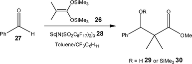 | ||
| Scheme 11 Illustration of the aldol reaction used to demonstrate the advantages of fluorous solvents in flow reactors. | ||
In addition to fluorinated solvents, ionic liquids have also been employed as a reaction media for flow reactions. Using 1-butyl-3-methylimidazolium bis(trifluoromethylsulfonyl)imide, Ryu et al.34 evaluated the continuous flow Heck reaction (Scheme 12) and subsequent recycling of the reaction solvent.
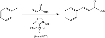 | ||
| Scheme 12 Illustration of the Heck reaction performed in a recyclable ionic liquid. | ||
Whilst authors have demonstrated rate acceleration as a result of utilising segmented flow,42 Buchwald and Nager43 recently reported the need for additional mixing of the immiscible toluene![[thin space (1/6-em)]](https://www.rsc.org/images/entities/char_2009.gif) :
:![[thin space (1/6-em)]](https://www.rsc.org/images/entities/char_2009.gif) water phases when performing a C–N cross coupling reaction (Scheme 13). Packing an FEP tube reactor with stainless steel spheres (60–125 μm), the authors observed 60% conversion of 2-chloroanisole 31 to ethyl 2-((2-methoxyphenyl)amino)benzoate 32 compared with 10% in an open tube reactor; rising to 98% conversion at a residence time of 6 min. Evaluating the effect of packed-bed size, the authors observed increased substrate conversion with increasing bed size, concluding that the higher fluid velocity resulted in increased mixing efficiency.
water phases when performing a C–N cross coupling reaction (Scheme 13). Packing an FEP tube reactor with stainless steel spheres (60–125 μm), the authors observed 60% conversion of 2-chloroanisole 31 to ethyl 2-((2-methoxyphenyl)amino)benzoate 32 compared with 10% in an open tube reactor; rising to 98% conversion at a residence time of 6 min. Evaluating the effect of packed-bed size, the authors observed increased substrate conversion with increasing bed size, concluding that the higher fluid velocity resulted in increased mixing efficiency.
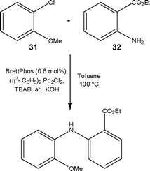 | ||
| Scheme 13 Model reaction used to demonstrate the C–N cross coupling under flow conditions. | ||
An interesting area that has received attention from researchers is the development of continuous methodology for the preparation of well defined semiconductor materials. Applying continuous flow processing to the synthesis of quantum dots, Jensen et al.45 reported the development and use of a high temperature and high pressure micro reactor suitable for the synthesis of nanocrystalline quantum dots. In addition to demonstrating an increase in the optical characteristics of the CdSe quantum dots, the authors were also able to replace conventional solvents such as squalane and octadecane with reduced toxicity solvents such as hexane, toluene and octane.
Principle 3: Less hazardous chemical syntheses
Whilst the toxicity and hazards associated with a specific final product do not alter with the production method employed, the fact that flow reactor technology has routinely been shown to generate products in higher yield and selectivities, it can be envisaged that the implementation of this technology at a production level has the potential to reduce the number and type of by-products generated and hence reduce the generation of hazardous products realised via side reactions.Principle 6: Design for energy efficiency
Over the past decade it has become widely accepted in academic circles that flow reactors offer the user the potential to intensify processes and thus reduce the energy impact of transformations employed at a production scale; with industrial researchers more recently reporting its application.In an early disclosure by industry, researchers at Degussa AG described the ability to boost production capacity of an existing tubular reactor plant by installing a wall-coated microstructured reactor upfront.46 Focussing on the synthesis of acroleinvia a gas-phase partial oxidation reaction, the authors determined that the process would afford a temperature rise of 133 °C when performed in a 10 mm (i.d.) tubular reactor, reducing to only 1.3 °C in a 1 mm tube. With this in mind, a wall-coated microstructured device was fabricated where the increased process control led to a reduction in operational costs previously associated with thermal management. Using this approach, the researchers calculated that for a highly exothermic reaction the use of such a system would enable a 20% increase in production capacity by exploiting micro process technology for the modification of existing plant infrastructure.
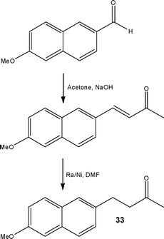 | ||
| Scheme 14 Two-step synthesis of Nabumetone 33 developed using microwave reactors and scaled using flow reactors. | ||
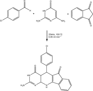 | ||
| Scheme 15 Illustration of a multi-component flow reaction promoted using inductive heating. | ||
An early example of photochemistry under flow was reported by Lu, Schmidt and Jensen,53 whereby the conversion of benzophenone to benzopinacol under UV irradiation (λ = 366 nm) was investigated in a silicon/quartz micro reactor (Channel dimensions = 500 μm2).
Maeda et al.54 subsequently investigated the intramolecular [2+2] and [2+3] photocycloaddition of 2-(2-alkenyloxymethyl)-naphthalene-1-carbonitriles, comparing the efficiency of reactions performed under standard and flow conditions (Channel dimensions = 2.5 mm (wide) × 60 mm (long)); employing a Xenon lamp (500 W, λ = 280 nm) (Scheme 16). Performing the reaction under flow conditions the authors were able to uniformly irradiate the reaction mixture, which not only reduced the irradiation time from 240 min to 1 min, but also minimised the proportion of photocycloreversion observed. Using this approach, the authors were able to selectively perform the desired [2+2] photocycloaddition, affording the 1,2-adduct in excellent selectivity (96%); demonstrating that when fast reversible reactions and slow irreversible reactions co-exist, micro reactors offer an efficient method for the synthesis of materials via the former reaction pathway. The generality of the technique developed was then investigated for a series of substituted carbonitriles whereby excellent selectivities were obtained when benchmarked against comparable photochemical batch reactions.
![Illustration of the intramolecular [2+2] and [2+3] photocycloaddition reactions of 2-(2-alkenyloxymethyl)-naphthalene-1-carbonitriles performed under flow conditions.](/image/article/2012/GC/c1gc16022b/c1gc16022b-s16.gif) | ||
| Scheme 16 Illustration of the intramolecular [2+2] and [2+3] photocycloaddition reactions of 2-(2-alkenyloxymethyl)-naphthalene-1-carbonitriles performed under flow conditions. | ||
Shvydkiv, Nolan and Oelgemöller,55 recently described the development of 4,4′-dimethoxybenzophenone 34 mediated microphotochemical transformations of phthalimides. Employing a Foturan™ micro reactor (Volume = 1.6 ml) and five 8 W UVA lamps (λ = 350 nm) as a light source, the authors investigated a series of photodecarboxylation addition (Scheme 17a) and cyclisation reactions (Scheme 17b).
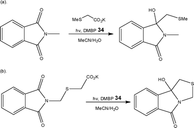 | ||
| Scheme 17 Illustration of photochemical (a) addition and (b) cyclisation reactions performed using a Foturan™ flow reactor. | ||
Compared to conventional cylindrical Schlenk apparatus, the authors calculated that the irradiated area of the micro reactor was 5 to 8 times larger than a 50–100 ml batch vessel and demonstrated larger energy efficiencies. Furthermore, decomposition processes were also avoided through the use of a flow reactor as ‘over-irradiation’ could be minimised. With these observations in mind, the researchers are currently exploring the development of a solid-supported mediator to aid with product purification.
Devices for the photochemical degradation of waste materials have also been developed as a means of reducing the impact of chemical production and waste treatment.56
In recent years Yoshida and co-workers58 have extensively explored this area of flow chemistry, concluding that a series of short living organolithium intermediates can be readily generated and reacted under flow conditions at temperatures greater than those conventionally required in batch. In an extension to this investigation, the authors have also demonstrated an additional advantage of flow reactors over batch vessels, that being the ability to readily perform reaction steps for precise times at different temperatures (Scheme 18).59
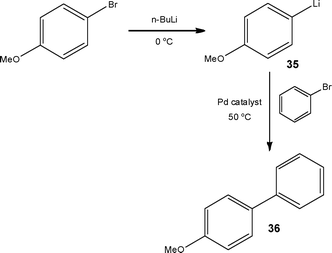 | ||
| Scheme 18 Sequential lithiation and Murashasi couplings performed at different temperatures under flow conditions. | ||
Under batch conditions, the authors formed the organolithium intermediate 35 at −78 °C, warming the reaction mixture to 30 °C to perform the Murahasi coupling, affording 53% 4-methoxybiphenyl 36, 7% 4-butylmethoxybenzene and 3% butylbenzene. In comparison, generation of the organolithium intermediate at 0 °C (Residence time = 2.6 s) in a flow reactor, followed by the coupling reaction at 30 °C (Residence time = 16 s) the authors were able to increase the yield of 4-methoxybiphenyl 36 to 80%. Further increasing the second reactor temperature to 50 °C enabled isolation of the biphenyl derivative 36 in 93% yield at a semi-preparative throughput of 15.6 g h−1. In other work the authors have also demonstrated the safe manipulation of sec-BuLi at −48 °C, representing a 30 °C increase compared to batch60 and the homocoupling of aryl halides using FeCl3.61 The manipulation of moisture sensitive reagents and their introduction into flow reactors can prove challenging, refer to ‘Challenges of flow reactor technology’ for details.
In addition to lithiations, other transformations have been shown to benefit from increased reactor temperature include the Swern-Moffatt oxidation15 (see Principle 1. Prevention of waste). In some cases reactor temperatures have been increased by 80 °C whilst having no detrimental effect on the reaction yield and product selectivity-giving access to a wide range of chemistries that may otherwise not be employed at a production-scale due to the need for cryogenic conditions. Looking towards production environments, this approach has potential to substantially reduce energy requirements and simultaneously the costs associated with the use of such synthetic pathways.
Principle 7. Use of renewable feedstocks
The use of renewable feedstocks in synthetic research is a relatively new area, examples of their application under flow conditions are however starting to appear in the literature. Using biphasic flow, Brasholz and Tsanaktsidis62 demonstrated the ability to synthesise value-added furan derivatives, such as 5-(chloromethyl)furfural 37 from renewable feedstocks (Scheme 19). Employing aqueous HCl at 130 °C, the authors reported the efficient dehydration of sucrose 38 to 5-(chloromethyl)furfural 37 at a throughput of 18.0 g min−1. | ||
| Scheme 19 Use of renewable feedstocks for the synthesis of value-added furan derivatives. | ||
As an extension, the authors also reported the ability to synthesise levulinic acid 39 from D-fructose 40 using 2.0 M HCl and MeOH as the reaction solvent. Employing a reactor temperature of 140 °C for 80 min, the target compound was obtained in 72% yield with 11% 5-(hydroxymethyl)furfural 41 (Scheme 20).
 | ||
| Scheme 20 Synthesis of levulinic acid 39 from D-fructose 40 under flow conditions. | ||
Looking towards the renewability of feedstocks, the generation of hydrogen from water and its subsequent use in hydrogenation reactions represent an area that has received significant interest from the flow chemistry community; see Principle 12 for examples using water as the H2 source.
Principle 8. Reduce derivatives
One approach to reducing the environmental burden of synthetic chemistry is to develop methodology that requires minimal or no protecting group steps.Whilst protecting group chemistry is by its very nature not atom efficient, Wild and co-workers63 were able to develop a novel, re-usable non-covalent N-protecting group strategy; which coupled with continuous flow enabled the synthesis of O-tyramine acetate 42 in high yield and selectivity. In comparison, when the reaction was performed in the absence of the protecting group, a mixture of tyramine acetate 42 (23%), tyramineN-acetate (12%), tyramine diacetate (20%) and residual starting material (45%) was obtained.
With a strategy based on the non-covalent N-protection via an immobilised crown ether, the authors were able to N-protect bifunctional compounds, which upon reaction could be released to afford the derivatised amine. Using the O-acetylation of tyramine 42 as a model reaction, the authors evaluated the synthetic strategy outlined in Scheme 21, obtaining the target compound 42 in quantitative yield and selectivity. In addition, using an organic base 43 as a releasing agent left the crown ether cavity free for subsequent use. Whilst the solid-supported reagent could be utilised in a stirred vessel, mechanical degradation occurs making efficient recovery after each step problematic. In addition, large volumes of solvent and reagents are required in order to perform each step when compared to the use of a packed-bed reactor. Whilst at a research level techniques such as ‘catch and release’ are shown to afford facile access to high purity materials, at a production level the procedures used to prepare and regenerate the solid-supported material must also be considered when assessing the environmental impact of a process.
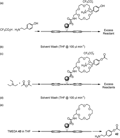 | ||
| Scheme 21 Schematic illustrating the reaction protocol used for the non-covelent protection of amines under flow conditions. | ||
More recently, Kim, Nagaki and Yoshida64 reported a flow reactor approach for the protecting group free synthesis and reaction of organolithium derivatives (Scheme 22). In conventional batch reactors, treatment of a ketone with an organolithium reagent would result in reaction. By carefully controlling the reaction time in a micro mixer (<0.003 s), the authors found it possible to generate aryllithium intermediates from substrates possessing a ketonic moiety without the need for formal protection; which was not possible using a stirred reactor. The synthetic utility of the methodology developed was subsequently demonstrated for the preparation of derivative 44, an intermediate used in the synthesis of the natural product Pauciflorol F 45 (Fig. 2). Using the micro reaction strategy described, the authors were able to synthesise compound 45 in 81% yield at a throughput of 12.7 g h−1.
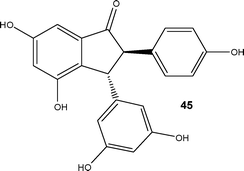 | ||
| Fig. 2 Natural product Pauciflorol F 45. | ||
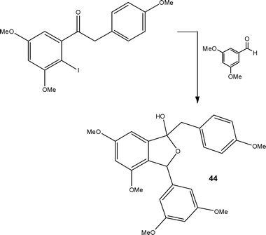 | ||
| Scheme 22 Illustration of the protecting group free synthesis of derivative 44, a key component in the synthesis of Pauciflorol F 45. | ||
The increased control micro reactors afford enables the user to exploit subtle differences in reaction rate in order to select the desired synthetic pathway over a competing one. This approach therefore has great potential for the modern synthetic chemist, enabling the realisation of protecting group free synthesis.
Principle 9. Catalysis
Catalysis is a powerful synthetic tool used to increase the efficiency and selectivity of reactions; however identification of suitable reaction conditions, catalyst loadings and type can be both laborious and consume significant quantities of precious material. With this in mind, micro flow reactors are advantageous as they enable rapid screening of catalysts towards and array of substrates whilst minimising the volume of catalysts required. Strategic examples are selected to illustrate the advantages associated with performing catalysed processes conducted under flow conditions.Utilising a Cu/Pd catalyst system, Underwood and Gooßen65 described the development of a new synthetic strategy for the decarboxylative biaryl synthesis performed under flow conditions (Scheme 23). When attempted under batch conditions, minimal C–C bond formation was observed (6%), with protodecarboxylation dominating to afford nitrobenzene 46 as the major product (Scheme 23). In comparison, when the reaction was performed under the same reaction conditions in a tubular flow reactor 4′-methyl-2-nitro-1,1′-biphenyl 47 was isolated in 71% yield, with no nitrobenzene 46 formation observed. The origin of this impressive C–C selectivity is currently the subject of further investigations by the authors.
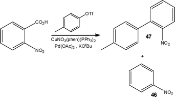 | ||
| Scheme 23 Decarboxylative biaryl synthesis and the accompanying protodecarboxylation by-product 46. | ||
In addition to employing homogeneous catalysts, several authors have described the used of heterogeneous catalysts within flow reactors as a means of increasing the ease and efficiency of catalyst recovery and recycle. Several methods have been employed to incorporate the catalyst into the reactors including packed-beds,65 monoliths66,67 and wall-coated systems (Au-films,68polymer brushes,69zeolites70 and Pd nanoparticles71) to exploit the high surface to volume areas obtained in micro channel devices, opening up the possibility to design and evaluate novel, selective catalyst types. For additional examples please see the tutorial review by Frost and Mutton72 and the references cited therein.
Using previously developed polymer brushes as a surface for functionalisation, Vancso and Verboom74 demonstrated the ability to efficiently incorporate a lipase biocatalyst (Candidia Rugosa type VII) onto the walls of silicon-glass micro reactors. Assessment of the devices using the BCA assay confirmed the immobilisation of 3.25–4.25 × 10⁻⁸ μg μm−2 of biocatalyst, depending on the coating time used and the thickness of the resulting catalytic layer; as with all immobilised biocatalysts, reduction in activity was observed compared to the free biocatalyst. Using the modified micro channel reactor, the authors were able to determine that the hydrolysis of nitrophenyl acetate was first order and extracted a rate constant of 22 × 10−3 s−1. More recently He, Greenway and Haswell75 combined biphasic flow with an immobilised lipase (C. antarcticalipase A) demonstrating the ability to biocatalytically hydrolyse 4-nitrophenyl butyrate at 80 °C without loss of activity over 480 h.
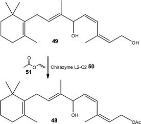
An early example of scaling a biocatalytic flow process was the lipase catalysed synthesis of (E)-retinyl acetate 48, an intermediate in the preparation of Vitamin A (Scheme 24), reported by Orsat, Wirz and Bischof.76 Starting from a 1,6-diol 49, the authors employed an immobilised Chirazyme L2-C250 as the biocatalyst and vinyl acetate 51 in acetone as the acylating agent. Employing a small packed-bed reactor, containing 5.0 g of Chirazyme L2-C250, the authors were able to synthesise (E)-retinyl acetate 48 in 99% yield and >97% selectivity affording a throughput of 49 g day−1. Scaling the technique to the mini-plant, the authors employed 120 g of biocatalyst 50 and evaluated the reactor for long-term stability. After a few days they observed a decrease in production efficiency, identifying deactivation as a result of feedstock impurities. Adding a protective pre-column, it was possible to operate the system at a throughput of 10 g min−1 (1.6 kg day−1) over a period of 100 days without needing to replace the pre-column. Isolation of the target product 48 was achieved viadistillation of acetaldehyde and rectification of residual vinyl acetate 51 allowed re-use.
 | ||
| Scheme 24 Biocatalytic synthesis of a key intermediate of Vitamin A. | ||
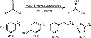
Whilst considerable research has been performed into the development of chiral organocatalysts, biocatalysts afford the ultimate atom efficient route enantiomerically pure products. Using crude enzyme lysates, containing hydroxynitrile lysate, Rutjes et al.77 evaluated the synthesis of a series of (S)-cyanohydrins in a glass microstructured reactor. Employing an organic phase containing the aldehyde (plus internal standard) and an aqueous solution containing potassium cyanide and the enzyme lysate, the effect of a fixed reaction time (12.5 min) on substrate reactivity was investigated under biphasic laminar flow. Using this approach, the authors obtained the target (S)-cyanohydrins in moderate to high yields, as illustrated in Scheme 25, with > 95% ee for aromatic substrates and ∼85% for aliphatic aldehydes. Employing (R)-P. amygdalus, the authors also investigated the synthesis of (R)-cyanohydrins using an automated screening platform to reduce biocatalyst consumption, an important consideration when selecting an appropriate biocatalyst for a specific transformation.
 | ||
| Scheme 25 Biocatalytic synthesis of cyanohydrins, developed under biphasic flow conditions. | ||
Principle 11. Real time analysis for pollution prevention
A key element of a production process is validation of product quality. Should part of a process deviate from the set condition i.e. dosing rate, temperature, it is imperative that the change be picked up and the effect on the process as a whole known. With this in mind, process analytics offer the ability to monitor a process in real-time, readily identifying deviations from the production target-allowing operators to more rapidly resolve issues and divert out of specification process streams before significant batches of material are spoiled. In addition to offering product quality management, process analytical tools (PAT) are also an important safety measure within the production environment. Whilst PAT such as on-line Raman and IR spectrometry find frequent application in the monitoring of industrial processes, the techniques are not yet widely exploited in synthetic research laboratories; however they have the potential to greatly increase the understanding of process at the research level. | ||
| Scheme 26 Model reaction used to demonstrate the identification of short-lived intermediates using online ESI-MS detection. | ||
In addition to analytical instrumentation, examples of specialised sensors have been reported within flow reactors as a means of monitoring changing in conduction which can be related to chemical conversion.82 Due to the specific nature of these sensors, they are relatively inexpensive and therefore demonstrate great potential for the monitoring of continuous flow processes.
For those that are interested in additional reading on this subject, an excellent review summarising the application of in-line monitoring within continuous flow process was recently published by McMullen and Jensen.83
Principle 12. Inherently safer chemistry for accident prevention
One of the potentially most interesting aspects of flow chemistry is ability to increase the safety profile of synthetic transformations through reactor engineering.Ebrahimi et al.84 investigated the production of unstable percarboxylic acids which find application as oxidisers in bleaches and disinfectants; comparing the safety rating with a batch process. In addition, the authors explored the possibility of developing micro processing systems to enable customers to generate the compounds at the point of use, concluding that this mode of operation would reduce the hazards, costs and environmental burden associated with transportation of these unstable materials.
In addition to speciality chemical production, a niche area that has benefited from increased process safety is that of gas-liquid reactions, for which access has previously been limited in the everyday synthetic laboratory.
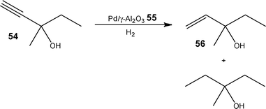
Again employing a capillary based system, this time derived from a GC column, Kreutzer and co-workers86 demonstrated the ability to eliminate axial dispersion, utilising gas-liquid segmented flow to gain access to product selectivities currently unobtainable using conventional techniques. Investigating the hydrogenation of 3-methyl-1-penten-3-ol 54, the authors employed a Pd impregnated γ-Al2O355 wall-coating as the catalyst (tunable Pd contents of 0.02–5.7 wt% Pd) and evaluated the effect of reaction time on the product distribution. Over the course of 1 day, the authors were able to optimise their system to attain a maximum yield of 78 ± 2% 56, which is in line with previous kinetic modelling studies (Scheme 27).87 In a subsequent experiment, the technique was applied to the hydrogenation of aliphatic azides, due to the pharmaceutical relevance of the resulting amines.
 | ||
| Scheme 27 Illustration of the over-oxidation product obtained for the hydrogenation of 3-methyl-1-penten-3-ol 54 in batch. | ||
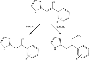
When commercially available flow chemistry equipment is discussed, more often than not the piece of equipment that comes to mind is the H-cube™ (Thalesnano, Hungary), the primary reason for this being that it is an engineered solution to a long-standing laboratory problem. With laboratory safety being at the forefront of the modern researchers mind, the development of a dedicated piece of equipment capable of performing hydrogenationsvia the in situ generation of hydrogen from water was inspired, removing the need for H2 cylinders within the laboratory, further increasing operator safety.88 Over the past 5 years, the equipment has been used for an array of gas-liquid-solid reductions such as nitro, alkene, alkyne, oxime and nitrile, along with debenzylations and deuterations. These examples have served to demonstrate not only increased process safety but also dramatic reductions in reaction time, enhanced catalytic lifetimes and increased product selectivity accessible through flow.89Scheme 28 illustrates a recent example utilising the H-cube™ in the synthesis of 2-phenyl-3-(1H-pyrrol-2-yl)propan-1-amines by Tarleton and McCluskey.90 For a discussion of recent advances in this area of flow chemistry, please refer to the review article of Kappe and co-workers.91
 | ||
| Scheme 28 Illustration of the key hydrogenation steps employed under flow conditions for the preparation of synthetically interesting pyrroles. | ||
Using a commercially available tube reactor, Hii et al.92 evaluated the Ru-catalysed oxidation of benzylic and allylic alcohols to aldehydes (and ketones) with >99% selectivity. Using air (15 bar) as the oxidant in place of O257, the authors demonstrated no change in reaction selectivity; illustrating a tolerance to halides and heteroatoms (S and N). In an extended application, the authors developed a tandem oxidation (90 °C, 1 h) and olefination (3 h) which could be performed without a solvent switch (Scheme 29).
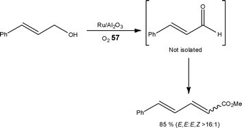 | ||
| Scheme 29 An example of a tandem oxidation and olefination reaction performed in toluene. | ||
Concurrently, Johnson, Yates and Stahl93 reported the development of a continuous flow process for the aerobic oxidation of alcohols using a dilute oxygen source (8% O257 in N2), taking inspiration from the commodity chemicals industry where selective oxidations are performed on large scales. A further advantage of the technique developed was that the authors operated outside the explosive regime which meant that decomposition of the Pd catalyst, to Pd metal, was avoided giving rise to potential recycle of the catalyst.
As observed with hydrogenations, laboratory flow equipment is also commercially available for ozonolyses, with the ozonolysis of 1-decene to nonanal at −10 °C demonstrated by Gavriilidis et al.94 Glasnov et al.95 recently demonstrated the high yielding ozonolysis of styrenes and thioanisole, whereby the methods developed were suitable for the preparation of up to 10 g of oxidised material per day (Scheme 30).
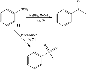 | ||
| Scheme 30 Illustration of the selective ozonolysis of thioanisole 58 achieved under flow conditions. | ||
By performing such reactions under controlled gas handling and with a suitable quench agent such as triphenyl phosphine, ozonolyses have the potential to become another routine addition to the synthetic chemists toolbox. See section 2.0 for an example of an ozonloysis performed at the tonne scale.
In a recent example, Sandford et al.97 reported for the first time the ability to combine gas-liquid and liquid–liquid reaction steps in the synthesis of 4-fluoropyrazole derivatives (Scheme 31). Employing a stream of F2 in N259 (10%), the first step of the reaction was performed in a nickel micro reactor, enabling the selective fluorination of 2,4-pentanedione 60 to afford 3-fluoropentane-2,4-dione 61 in quantitative conversion. The output of the nickel reactor was then connected to a T-piece where a solution of hydrazine derivative (1.5 eq.) in MeCN, EtOH or H2O was mixed and the cyclisation reaction performed in a PTFE tube reactor. Using this approach, the authors were able to obtain the 4-fluoropyrazole derivatives in moderate to high yields (66–83%), with product purities determined using offline 19F NMR spectroscopic analysis.
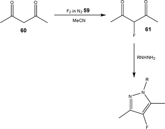 | ||
| Scheme 31 Illustration of the selective fluorination step used to synthesise 4-fluoropyrazoles. | ||
In addition to gas-liquid fluorinations, several authors have also reported the successful performance of liquid–liquid fluorinations employing reagents such as DAST (diethylaminosulfur trifluoride) 62. The details of a comprehensive study was reported by Seeberger and co-workers98 who identified that fluorinations could be performed in a simple PTFE tubular reactor (volume = 16 ml) by mixing the substrate with DAST 62 at a T-mixer, followed by quenching using NaHCO3. Scheme 32 illustrates an example of the transformation performed on a complex alcohol 63 whereby the target fluorinated analogue 64 was obtained in 61% yield as a 6![[thin space (1/6-em)]](https://www.rsc.org/images/entities/char_2009.gif) :
:![[thin space (1/6-em)]](https://www.rsc.org/images/entities/char_2009.gif) 1 mixture of diastereomers.
1 mixture of diastereomers.
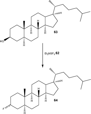 | ||
| Scheme 32 Fluorination of alcohols using DAST 62 under flow conditions. | ||
Whilst from the examples provided it can be seen that there are some obvious benefits associated with increasing the ease with which flammable gases are generated and manipulated, the safety profile of liquid–liquid phase reactions has also been shown to be increased through the use of flow reactor technology. The following section includes several a examples of the techniques applied to the large-scale production of fine chemicals and pharmaceuticals.
Production-scale processes
From the examples provided it is clear that flow processing has the advantage of providing the researcher access to a series of previously forbidden transformations using either homemade or commercially available platforms. When it comes to production, reactor safety is key and with the foundations of the technology being the facile up-scaling of bench process to production, it comes as no surprise that a series of large-scale examples have been reported by the fine chemical and pharmaceutical industries, with system engineers reporting the fabrication of both dedicated and flexible installations.99Liquid–liquid phase
In an early example of micro reaction engineering, Kirschneck and Tekautz,100 reported the installation of a StarLam 3000 static micro mixer and tube reactor for the performance of a two-stage industrial reaction. Conventionally performed in a 10 m3 batch reactor at a throughput of 1800 kg h−1, with a reaction time of 4 h, the authors were able to double the system productivity to 3600 kg h−1 employing a reaction time of 60 s and demonstrating significant energy savings. At the point of reporting, the system had been installed for 18 months and had been operated with no operational problems reported. After ten months in use, the mixer was dismantled from the system and inspection revealed no corrosion; demonstrating the applicability of micro-structured reactors to fine chemical production.de Mello and co-workers101 illustrated at the bench-scale, the potential of micro reactors for the continuous flow synthesis of azo-dyes, highlighting that operator safety was increased as a result of performing the diazotisationin situ. The technique was subsequently exploited for the transformation of anilines to aryl chlorides under continuous flow conditions using the Sandmeyer reaction.102 Building on this initial work, Wille et al.103 employed a three-stage pilot plant for the synthesis of an undisclosed azo-dye capable of operating at a throughput of 30 L h−1. Pennemann and co-workers104 subsequently described improvements in pigment quality as a result of employing flow processing for the production of Yellow-12 65 (Fig. 3); with improved particle size distribution, glossiness and transparency among the metrics reported.
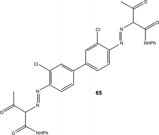 | ||
| Fig. 3 Illustration of Yellow-12 65 an azo-dye produced under flow conditions. | ||
Looking towards the production of highly energetic materials, Loebbecke et al.105 described the construction of a micro reaction plant for the synthesis and downstream processing of nitrate esters. Owing to the thermallability of the materials, a remote controlled reactor was constructed and the optimisation of an undisclosed material performed; enabling the evaluation of process parameters that would have previously remained uninvestigated. Once identified, the optimal processing conditions were transferred an automated multi-purpose plant where continuous synthesis of the explosive materials was performed; incorporating downstream processes such as washing and extraction. Using this approach the authors were able to synthesise materials such as trinitroglycerin at a pharmaceutical grade with throughputs of 9 kg h−1.
Experiencing significant temperature rises (180 to 445 °C) during a key synthetic step in the preparation of a drug candidate 66, researchers at Bristol Myers Squibb proposed a safe process could be developed through the application of continuous flow.
Employing a stainless steel tube reactor, heated to 220 °C, the authors investigated the effect of reaction time (3.5–17.7 min) Claisen re-arrangement of propargyl ether 67 to 6-cyano-2,2-dimethylchromene 68; observing >96% conversion under all conditions explored (Scheme 33).106
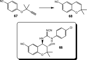 | ||
| Scheme 33 Illustration of the Claisen re-arrangement which forms a key step in the synthesis of the benzopyran-based potassium channel activator 66 of BMS. | ||
Increasing the reactor volume, the authors readily scaled the process to afford the benzopyran 68 derivative in 91% yield at a throughput of 7 kg h−1. By controlling the exothermicity of the reaction, the authors were also able to increase the quality of the product generated, with purities > 96% obtained over four 40 g batches.
Gas-liquid phase
In addition to the laboratory scale examples of ozonolysis reactions, Roberge and Nobis107 recently published details of a tonne-scale ozonolysis reaction performed under flow conditions. Looking to the conversion of chrysanthemic ester 69, as illustrated in Scheme 34, the authors were able to develop a safe method of synthesising the corresponding aldehyde 70-a key intermediate of an insecticide. Utilising a 450 L loop reactor, the ester was safely reacted with ozone 71 in a process that was optimised to a production scale of 0.5 tonne day−1; with Lonza demonstrating the manufacture of commercial quantities of the material. | ||
| Scheme 34 Oxidation of chrysanthemic ester 69 to the aldehyde 70 which is a key intermediate in the synthesis of an insecticide. | ||
With a view to reducing scaling issues associated with a key oxidation step, which required 16–24 h at −70 °C in batch, LaPorte and co-workers108 developed a three-stage continuous flow process for the synthesis of 6-hydroxybuspirone 72 (Scheme 35). Utilising a pre-formed enolate 73, the authors investigated its reaction with oxygen 57 at a reactor temperature of −10 °C and addition of triethylphosphite 74 afforded the target product 72 in 65–70% conversion; which was readily increased to 85–92% by the addition of a second stream of O257; affording a throughput of 300 g day−1. Compared to the previous process, reaction times were reduced to 5 min and large cost savings harnessed by increasing the reactor temperature by 60 °C for the oxidation step.
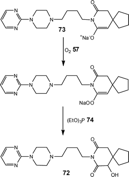 | ||
| Scheme 35 Illustration of the synthetic route developed for the continuous processing of 6-hydroxybuspirone 72. | ||
Challenges of flow reactor technology
Whilst it can be seen from the examples provided that flow reactor technology is an emerging technique that will benefit many synthetic researchers over the years to come, a recent publication by Ley and co-workers109 succinctly combines a practical description of the advantages and disadvantages of continuous flow processing.22 In this report, the authors highlight on one hand the processing advantages associated with the performance of reactions under cryogenic conditions; without the need for liquid N2 or solid CO2 baths. On the other hand, the authors detail the challenges associated with the manipulation of highly corrosive reagents and the foresight required in order to prevent precipitation of intermediates and products within the reactor coil itself. Once time is spent to overcome these technical challenges, the result is a segmented flow process capable of rapidly preparing pinacol boronate esters at a maximum product concentration of 0.2 M in moderate to high yield and > 95% purity; after an offline aqueous extraction (Scheme 36).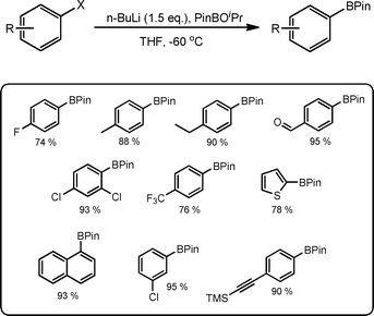 | ||
| Scheme 36 Illustration of the synthetic route to pinacol boronate esters under segmented flow conditions. | ||
Another significant aspect of flow reactor research that is often over-looked by those new to the field is the importance of selecting the correct reactor for the process under investigation. Of the wide number of reactors available, it is imperative that the user select the correct one for the task at hand, this can include (but not exhaustively) wetted material type, pumping mechanism, reactor size and mixer type. This is illustrated in an example by Browne et al.110 where the manipulation of slurries would be unsuitable in a tube reactor however the hydroiodide salt of N-iodomorpholine 75 (Scheme 37) is efficiently prepared at a throughput of 3.9 kg week−1; even in this case however it must be noted that homogeneous solutions were required to dose the reagents due to the pumping technology employed.
 | ||
| Scheme 37 Iodination of morpholine 76 in an agitated cell reactor to afford the hydroiodide salt of N-iodomorpholine 75. | ||
Summary
For the chemical industry to realise its potential in developing sustainable processes, it is imperative that the link between research chemists and process engineers continues to strengthen. Going forward, the focus of the chemical sector therefore needs to centre on the development of practices which continue to reduce waste and increase sustainability, whilst maintaining high production qualities.Through improvements in process control, continuous flow methodology has the ability to play an integral role in revolutionising the chemical sector, not only from an environmental standpoint but also from a quality, safety and economic perspective. Further work is required to address the challenges associated with the manipulation of slurries and the recovery of solvents and catalysts in order to expand the reaction types that can benefit from flow processing.
Notes and references
- C.-J. Li and B. M. Trost, Proc. Natl. Acad. Sci. U. S. A., 2008, 105(36), 13197–13202 CrossRef CAS.
- C. Jiménez-González, P. Poechlauer, Q. B. Broxterman, B.-S. Yang, D. AmEnde, J. Baird, C. Bertsch, R. E. Hannah, P. Dell'Orco, H. Noorman, S. Yee, R. Reintjens, A. Wells, V. Massonneau and J. Manley, Org. Proc. Res. Dev., 2011, 15, 900–911 Search PubMed.
- V. Hessel, D. Kralisch and U. Krtschil,, Energy Environ. Sci., 2008, 1, 467–478 CAS.
- E. D. Lavric and P. Woehl, Chemistry Today, 2009, 27, 45–48 CAS.
- C. Wiles and P. Watts,, Chem. Commun., 2011, 47, 6512–6535 RSC; B. P. Mason, K. E. Price, J. L. Steinbacher, A. R. Bogdan and D. T. McQuade, Chem. Rev., 2007, 107, 2300–2318 CrossRef CAS.
- S. Marre, A. Adamo, S. Basak, C. Aymonier and K. F. Jensen, Ind. Eng. Chem. Res., 2010, 49, 11310–11320 CrossRef CAS.
- V. Hessel, Chem. Eng. Technol., 2009, 32, 1655–1681 CrossRef CAS.
- P. T. Anastas and M. M. Kirchhoff, Acc. Chem. Res., 2002, 35, 686–694 CrossRef CAS.
- R. A. Sheldon, Pure Appl. Chem., 2000, 72, 1233–1246 CrossRef CAS.
- G. Kaupp, CrystEngComm, 2006, 8, 794–804 RSC.
- T. Schwalbe, V. Autze, M. Hohmann and W. Stirner, Org. Process Res. Dev., 2004, 8, 440–454 CrossRef CAS.
- H. Löwe, V. Hessel, P. Löb and S. Hubbard, Org. Process Res. Dev., 2006, 10, 1144–1152 CrossRef.
- A. Renken, V. Hessel, P. Löb, R. Miszczuk, M. Uerdingen and L. Kiwi-Minsker, Chem. Eng. Process., 2007, 46, 840–845 CrossRef CAS.
- H. Oyamada, T. Naito and S. Kobayashi, Beilstein J. Org. Chem., 2011, 7, 735–739 CrossRef CAS.
- P. J. Nieuwland, K. Koch, N. van Harskamp, R. Wehrens, J. C. M. van Hest and F. P. J. T. Rutjes,, Chem.–Asian J., 2010, 5, 799–805 CrossRef CAS.
- J. P. McMullen, M. T. Stone, S. L. Buchwald and K. F. Jensen, Angew. Chem., Int. Ed., 2010, 49, 7076–7080 CrossRef CAS.
- B. M. Trost, Acc. Chem. Res., 2002, 35, 695–705 CrossRef CAS.
- T. Razzaq, T. N. Glasnov and C. O. Kappe, Eur. J. Org. Chem., 2009, 1321–1325 CrossRef CAS.
- S. Ceylanm, C. Friese, C. Lammel, K. Mazac and A. Kirschning, Angew. Chem., Int. Ed., 2008, 47, 8950–8953 CrossRef.
- U. Tilstam, T. Defrance, T. Giard and M. D. Johnson, Org. Process Res. Dev., 2009, 13, 321–323 CrossRef CAS.
- D. A. Snyder, C. Noti, P. H. Seeberger, F. Schael, T. Bieber and W. Ehrfeld, Helv. Chim. Acta, 2005, 88, 1–9 CrossRef CAS.
- C. Wiles and P. Watts, Micro Reaction Technology in Organic Synthesis, 2011, CRC-Press Search PubMed.
- B. Hallmark, M. R. Mackley and F. Gadala-Maria, Adv. Eng. Mater., 2005, 7, 545–547 CrossRef CAS.
- A. Odedra and P. H. Seeberger, Angew. Chem., Int. Ed., 2009, 48, 2699–2702 CrossRef CAS.
- B. Gutmann, J.-P. Roduit, D. Roberge and C. O. Kappe, Angew. Chem., Int. Ed., 2010, 49, 7101–7105 CrossRef CAS.
- B. Gutmann, T. N. Glasnov, T. Razzaq, W. Goessler, D. M. Roberge and C. O. Kappe, Beilstein J. Org. Chem., 2011, 7, 503–517 CrossRef CAS.
- N. Zaborenko, E. R. Murphy, J. G. Kralj and K. F. Jensen, Ind. Eng. Chem. Res., 2010, 49, 4132–4139 CrossRef CAS.
- C. H. Hornung, C. Guerrero-Sanchez, M. Brasholz, S. Saubern, J. Chiefari, G. Moad, E. Rizzardo and S. H. Thang, Org. Process Res. Dev., 2011, 15, 593–601 CrossRef CAS.
- B. Ahmed-Omer and A. J. Sanderson, Org. Biomol. Chem., 2011, 9, 3854–3862 CAS.
- A. Russom, C. Jonsson, G. Stemme, S. J. Haswell, H. Anderson and C. Moberg, 8th International Conference on Miniaturised Systems for Chemistry and Life Sciences, 2004, p. 878 Search PubMed.
- F. Bonfils, I. Cazaux, P. Hodge and C. Caze, Org. Biomol. Chem., 2006, 4, 493–497 CAS.
- C. Capello, U. Fischer and K. Hungerbühler, Green Chem., 2007, 9, 927–934 RSC.
- K. Mikami, M. Yamanaka, M. N. Islam, K. Kudo, N. Seino and M. Shinoda, Tetrahedron, 2003, 59, 10593–10597 CrossRef CAS.
- S. Liu, T. Fukuyama, M. Sato and I. Ryu, Org. Process Res. Dev., 2004, 8, 477–481 CrossRef CAS.
- C. N. Baroud and H. Willaime, C. R. Phys., 2004, 5, 547–555 CrossRef CAS.
- R. Pestman and J. Jovanovic, Speciality Chem., 2011, 24–25 CAS.
- E. Sinkovec and M. Krajnc, Org. Process Res. Dev., 2011, 15, 817–823 CAS.
- S. L. Poe, M. A. Cummings, M. P. Haaf and D. T. McQuade, Angew. Chem., Int. Ed., 2006, 45, 1544–1548 CrossRef CAS.
- S. J. Dolman, J. L. Nyrop and J. T. Kuethe, J. Org. Chem., 2011, 76, 993–996 CrossRef CAS.
- R. L. Hartman, J. R. Naber, N. Zabrenko, S. L. Buchwald and K. F. Jensen, Org. Process Res. Dev., 2010, 14, 1347–1357 CrossRef CAS.
- T. Noël, J. R. Naber, R. L. Hartman, J. P. McMullen, K. F. Jensen and S. L. Buchwald, Chem. Sci., 2011, 2, 287–290 RSC.
- B. Ahmed-Omer, D. A. Barrow and T. Wirth, Tetrahedron Lett., 2009, 50, 3352–3355 CrossRef CAS.
- J. R. Naber and S. L. Buchwald, Angew. Chem., Int. Ed., 2010, 49, 9469–9474 CrossRef CAS.
- H. Kawanani, K. Matsushima, M. Sato and Y. Ikushima, Angew. Chem., Int. Ed., 2007, 46, 6284–6288 CrossRef.
- S. Marre, J. Baek, J. Park, M. G. Bawendi and K. F. Jensen, J. Assoc. Lab. Autom., 2009, 367–373 CrossRef CAS.
- S. Becht, R. Franke, A. Geißelmann and H. Hahn, Chem. Eng. Technol., 2007, 30, 295–299 CrossRef CAS.
- J. D. Moseley and C. O. Kappe, Green Chem., 2011, 13, 794–806 RSC.
- T. Razzaq and C. O. Kappe, ChemSusChem, 2008, 1, 123 CrossRef CAS.
- M. C. H. L. Dressen, B. H. P. Van de Kruijs, J. Meuldijk, J. A. J. M. Vekemans and L. A. Hulshof, Org. Process Res. Dev., 2010, 14, 351 CrossRef CAS.
- D. Obermayer, T. N. Glasnov and C. O. Kappe, J. Org. Chem., 2011, 76, 6657–6669 CrossRef CAS.
- M. Viviano, T. N. Glasnov, B. Reichart, G. Tekautz and C. O. Kappe, Org. Process Res. Dev., 2011, 15, 585–870 CrossRef.
- S. Ceylan, L. Coutable, J. Wegner and A. Kirschning, Chem.–Eur. J., 2011, 17, 1884–1893 CrossRef CAS.
- H. Lu, M. A. Schmidt and K. F. Jensen, Lab Chip, 2001, 1, 22–28 RSC.
- H. Mukae, H. Maeda, S. Nashihara and K. Mizuno, Bull. Chem. Soc. Jpn., 2007, 80(6), 1157–1161 CrossRef CAS.
- O. Shvydkiv, K. Nolan and M. Oelgemöller, Beilstein J. Org. Chem., 2011, 7, 1055–1063 CrossRef CAS.
- Z. He, Y. Li, Q. Zhang and H. Wang, Appl. Catal., B, 2010, 93, 376–382 CrossRef CAS.
- T. Schwalbe, A. Kursawe and J. Sommer, Chem. Eng. Technol., 2005, 28, 408–419 CrossRef CAS.
- A. Nagaki, S. Yamada, M. Doi, Y. Tomida, N. Takabayashi and J. Yoshida, Green Chem., 2011, 13, 1110–1113 RSC.
- A. Nagaki, A. Kenmoku, Y. Moriwaki, A. Hayashi and J. Yoshida,, Angew. Chem., Int. Ed., 2010, 49, 7543–7547 CrossRef CAS.
- A. Nagaki, E. Takizawa and J. Yoshida, J. Am. Chem. Soc., 2009, 13, 1654–1655 CrossRef.
- A. Nagaki, Y. Uesugi, Y. Tomida and J. Yoshida, Beilstein J. Org. Chem., 2011, 7, 1064–1069 CrossRef CAS.
- M. Brasholz, K. Von Känel, C. H. Hornung, S. Saubern and J. Tsanaktsidis, Green Chem., 2011, 13, 1114–1117 RSC.
- G. P. Wild, C. Wiles, P. Watts and S. J. Haswell, Tetrahedron, 2009, 65, 1618–1629 CrossRef CAS.
- H. Kim, A. Nagaki and J. Yoshida,, Nat. Commun., 2011, 2, 264 CrossRef.
- P. P. Lange, L. J. Gooßen, P. Podmore, T. Underwood and N. Sciammetta, Chem. Commun., 2011, 47, 3628–3630 RSC.
- A. El Kadib, R. Chimenton, A. Sachse, F. Fajula and B. Coq, Angew. Chem., Int. Ed., 2009, 48, 4969–4972 CrossRef CAS.
- C. J. Smith, C. D. Smith, N. Nikbin, S. V. Ley and I. R. Baxendale, Org. Biomol. Chem., 2011, 9, 1927–1937 CAS.
- G. Shore, M. Tsimerman and M. G. Organ, Beilstein J. Org. Chem., 2009, 5(No. 35) CAS.
- F. Costantini, W. P. Bula, R. Salvio, J. Huskens, H. J. G. E. Gardeniers, D. N. Reinhoudt and W. Verboom, J. Am. Chem. Soc., 2009, 131, 1650–1651 CrossRef CAS.
- W. Lau, K. L. Yeung and R. Martin-Aranda, Microporous Mesoporous Mater., 2008, 115, 156–163 CrossRef CAS.
- E. V. Rebrov, A. Berenguer-Murcia, H. E. Skelton, B. F. G. Johnson, A. E. H. Wheatley and J. C. Schouten, Lab Chip, 2009, 9, 503–506 RSC.
- C. G. Frost and L. Mutton, Green Chem., 2010, 12, 1687–1703 RSC.
- J. W. Swarts, R. C. Kolfschoten, M. C. A. A. Jansen, A. M. Janssen and R. M. Boom, Chem. Eng. J., 2010, 162, 301–306 CrossRef CAS.
- F. Constantini, E. M. Benetti, D. N. Reinhoudt, J. Huskens, G. J. Vancso and W. Verboom, Lab Chip, 2010, 10, 3407–3412 RSC.
- P. He, G. M. Greenway and S. J. Haswell, Process Biochem., 2010, 45, 593–597 CrossRef CAS.
- B. Orsat, B. Wirz and S. Bishof, Chimia, 1999, 53, 579–584 CAS.
- K. Koch, R. J. F. Van den berg, P. J. Nieuwland, R. Wijtmans, H. E. Shoemaker, J. C. M. van Hest and F. P. J. T. Rutjes, Biotechnol. Bioeng., 2008, 99, 1028–1033 CrossRef CAS.
- S. Mozharov, A. Nordon, D. Littlejohn, C. Wiles, P. Watts, P. Dallin and J. M. Girkin, J. Am. Chem. Soc., 2011, 133, 3601–3608 CrossRef CAS.
- T. M. Floyd, M. A. Schmidt and K. F. Jensen, Ind. Eng. Chem. Res., 2005, 44, 2351–2358 CrossRef CAS.
- C. F. Carter, I. R. Baxendale, M. O'Brien, J. B. J. Pavey and S. V. Ley, Org. Biomol. Chem., 2009, 7, 4594–4597 CAS.
- B. V. Silva, F. A. Violante, A. C Pinto and L. S. Santos, Rapid Commun. Mass Spectrom., 2011, 25, 423–428 CrossRef CAS.
- T. Jacobs, C. Kutzner, M. Kropp, W. Lang, A. Kienle and P. Huptmann, Procedia Chem., 2009, 1, 148–151 CrossRef CAS.
- J. P. McMullen and K. F. Jensen, Annu. Rev. Anal. Chem., 2010, 3, 19–42 CrossRef CAS.
- F. Ebrahimi, E. Kolehmainene and I. Turunen, Org. Process Res. Dev., 2009, 13, 965–969 CrossRef CAS.
- M. O'Brien, N. Taylor, A. Polyzos, I. R. Baxendale and S. V. Ley, Chem. Sci., 2011, 2, 1250–1257 RSC.
- J. J. W. Bakker, M. M. P. Zieverink, R. W. E. G. Reintjens, F. Kapteijn, J. A. Moulijn and M. T. Kreutzer, ChemCatChem., 2011, 7, 1155–1157 CrossRef.
- T. A. Nijhuis, G. Van Koten, F. Kapteijn and J. A. Moulijn, Catal. Today, 2003, 79–80, 315 CrossRef CAS.
- R. Jones, L. Godorhazy, N. Varge, D. Szalay, L. Urge and F. Darvas, J. Comb. Chem., 2006, 8, 110–116 CrossRef CAS.
- S. Lou, P. Dai and S. E. Schaus, J. Org. Chem., 2007, 72, 9998–10008 CrossRef CAS.
- M. Tarleton and A. McCluskey, Tetrahedron Lett., 2011, 52, 1583–1586 CrossRef CAS.
- M. Irfan, T. N. Glasnov and C. O. Kappe, ChemSusChem, 2011, 4, 300–316 CrossRef CAS.
- N. Zotova, K. Hellgardt, G. H. Kelsall, A. S. Jessiman and K. K. Hii, Green Chem., 2010, 12, 2157–2163 RSC.
- X. Ye, M. D. Johnson, T. Diao, M. H. Yates and S. S. Stahl, Green Chem., 2010, 12, 1180–1186 RSC.
- M. D. Roydhouse, A. Ghaini, A. Constantinou, A. Cantu-Perez, W. B. Motherwell and A. Gavriilidis, Org. Process Res. Dev., 2011 DOI:10.1021/op200036d.
- M. Irfan, T. N. Glasnov and C. O. Kappe, Org. Lett., 2011, 13, 984–987 CrossRef CAS.
- R. D. Chambers and R. C. H. Spink, Chem. Commun., 1999, 883–884 RSC.
- J. R. Breen, G. Sandford, D. S. Yufit, J. A. K. Howard, J. Fray and B. Patel, Beilstein J. Org. Chem., 2011, 7, 1048–1054 CrossRef CAS.
- T. Gustafsson, R. Gilmour and P. H. Seeberger, Chem. Commun., 2008, 3022–3024 RSC.
- D. Kirschneck and H. Haas, Speciality Chem., 2011, 26–28 CAS.
- D. Kirschneck and G. Tekautz, Chem. Eng. Technol., 2007, 30, 305–308 CrossRef CAS.
- R. C. R. Wootton, R. Fortt and A. J. de Mello, Lab Chip, 2002, 2, 5–7 RSC.
- R. Fortt, R. C. R. Wootton and A. J. de Mello, Org. Process Res. Dev., 2003, 7, 762–768 CrossRef CAS.
- Ch. Wille, H. P. Gabski, Th. Haller, H. Kim, L. Unverdorben and R. Winter, Chem. Eng. J., 2004, 101, 179–185 CrossRef CAS.
- H. Pennemann, S. Forster, J. Kinkel, V. Hessel, H. Löwe and L. Wu, Org. Process Res. Dev., 2005, 9, 188–192 CrossRef CAS.
- S. Loebbecke, D. Boskovic, T. Tuercke, A. Mendel and J. Antes, 11th International Conference on Microreaction Technology, Kyoto, 2010, 82–83 Search PubMed.
- R. J. Bogaert-Alvarez, P. Demena, G. Kodersha, R. E. Polomski, N. Soundararajan and S. S. Y. Wang, Org. Process Res. Dev., 2001, 5, 636–645 CrossRef CAS.
- M. Nobis and D. M. Roberge, Chemistry Today, 2011, 29, 56–58 CAS.
- T. L. LaPorte, M. Hamedi, J. S. DePue, L. Shen, D. Watson and D. Hsieh, Org. Process Res. Dev., 2008, 12, 956–966 CrossRef CAS.
- D. L. Browne, M. Baumann, B. H. Harji, I. R. Baxendale and S. V. Ley, Org. Lett., 2011, 13, 3312–3315 CrossRef CAS.
- D. L. Browne, B. J. Deadman, R. Ashe, I. R. Baxendale and S. V. Ley, Org. Process Res. Dev., 2001, 15, 693–697 CrossRef.
| This journal is © The Royal Society of Chemistry 2012 |
