Superior radical polymer cathode material with a two-electron process redox reaction promoted by graphene†
Wei
Guo‡
,
Ya-Xia
Yin
,
Sen
Xin‡
,
Yu-Guo
Guo
* and
Li-Jun
Wan
Beijing National Laboratory for Molecular Sciences (BNLMS), Center for Molecular Sciences, Institute of Chemistry, Chinese Academy of Sciences (CAS), Beijing, 100190, P. R. China. E-mail: ygguo@iccas.ac.cn; Fax: +86-10-62557908; Tel: +86-10-62557908
First published on 6th September 2011
Abstract
Poly(2,2,6,6-tetramethyl-1-piperidinyloxy-4-yl methacrylate) (PTMA) displays a two–electron process redox reaction, high capacity of up to 222 mA h g−1, good rate performance and long cycle life, which is promoted by graphene as cathode material for lithium rechargeable batteries.
Broader contextThe demand for green lithium ion batteries (LIBs) with increasing use of renewable energy is continuously increasing because of sustainable energy and environmental issues. This requires scientists to search for various electrode materials to meet the demands. Cathode material is a bottleneck in lithium ion batteries, especially in the application of LIBs in EV/HEV due to its low power capacity and low theoretical capacity compared to that of anode materials. Organic cathode materials can provide higher capacity because of some special reaction mechanisms and alterable chemical structures, and can also be prepared from renewable resources and eco-friendly processes coupled with a simple recycling management. Stable radical polymers are emerging as a promising choice of such new cathode materials. At present, many questions regarding the reaction mechanisms and structure of the radical polymers are not well understood. Here we report a superior cathode material, poly(2,2,6,6-tetramethylpiperidinyloxy-4-yl methacrylate) (PTMA)/graphene composite. The composite shows high capacity, high rate capability and ultra-long cycle life, benefiting from a two-electron process redox reaction and an electronic wiring of graphene. The detailed reaction mechanisms of the composite are also discussed. The PTMA/graphene composite promises good application in stationary energy storage devices. |
High-performance lithium-ion batteries have attracted continuous attention for satisfying the demands of communication, portable electronic devices, electric vehicles (EVs) and hybrid EVs (HEVs).1–5 Compared with the anode materials, it is challenging to design high-capacity, low-cost and environmentally-friendly cathode materials.6 The cathode materials generally used in lithium-ion batteries are inorganic materials (e.g., LiCoO2, LiMn2O4, and LiFePO4),7–12 which however, suffer from some drawbacks involving the limited theoretical capacities, the unrenewable mineral resources, and the large energy consumption during synthesis. As an alternative approach, organic compounds have been investigated for renewable resources prepared by eco-efficient processes, which allow their structures to be tailored according to different applications.13–18
Organic-based electrode materials have some inherent advantages: lightness, environmentally-benign characteristics, mechanical flexibility, and processing compatibility. Many organic materials have been developed for lithium rechargeable batteries, including organic conductive polymers (polyaniline, polythiophene and polyimide),19,20organosulfur compounds,21carbonyl-based compounds22–25 and stable radical polymers.26,27 Among the radical polymers, poly(2,2,6,6-tetramethylpiperidinyloxy-4-yl methacrylate) (PTMA), a derivative of polymethacrylate with a 2,2,6,6-tetramethyl-1-piperidinyloxy (TEMPO) radical in the repeating unit, was first reported by Nakahara et al. as the cathode-active material,28 which exhibited high capacity, high charging and discharging rate performance, and long cycle life.29 When assuming one electron per monomer unit taking part in the redox reaction at an average discharge voltage of 3.5 V for the organic radical battery with negative electrode of lithium metal, the theoretical capacity of PTMA is 111 mA h g−1, which is slightly lower than some inorganic cathode materials, such as LiFePO4.29,30 It is reported that DNA complexes containing TEMPO radicals displayed a reversible two-stage charge/discharge process,31 indicating that TEMPO can have a two-electron redox reaction. Due to the low conductivity of PTMA, much effort is focused on the preparation of PTMA membrane electrode32 and electrode material composites (such as PTMA/carbon composite).33–35Graphene has recently been demonstrated as a promising material because of its distinctive band structure and physical properties (such as superior thermal conductivity, high mechanical strength, high electrical and electrochemical properties).36–40 Three-dimensional (3D) graphene networks have been used for inorganic electrode materials and polymers for improving the electronic conductivities of composites.41–47 However, according to our knowledge, there is no report on the introduction of graphene into radical polymers such as PTMA, which needs to improve their electronic conductivities. Here, we report the possibility of combining PTMA and graphene 3D networks towards improved electrochemical performance in lithium-ion batteries.
In this communication, we have prepared PTMA/graphene composite with graphene as electronic conductivity promoter. Particularly, PTMA/graphene composite showed a two-electron process redox reaction (reversible two-stage charge/discharge processes), good rate performances, long life, and high capacity approaching the theoretical capacity (222 mA h g−1 in the voltage of 2–4 V, larger than LiFePO4, 170 mA h g−1).
PTMA was prepared according to the reported method with minor modifications (Scheme 1).282,2,6,6-tetramethylpiperidine methacrylate (MTMP) monomer was polymerized using 2,2′-azobisisobutyronitrile (AIBN) radical initiator, and then oxidized with H2O2 in the presence of Na2WO4 catalyst at 60 °C to obtain PTMA (see experimental section in the ESI†). Fig. 1 shows the infrared (IR) spectra of PTMA with MTMP monomer for comparison. MTMP shows the characteristic absorption peaks at 1634, 1705 and 3400 cm−1, corresponding to the C![[double bond, length as m-dash]](https://www.rsc.org/images/entities/char_e001.gif) C, C
C, C![[double bond, length as m-dash]](https://www.rsc.org/images/entities/char_e001.gif) O and N–H groups, respectively (Fig. 1a). After polymerization, no absorption peaks were observed at 1634 and 3400 cm−1, but instead a new absorption peak at 1362 cm−1 assignable to the nitroxyl radical of PTMA (Fig. 1b). Fig. 1c shows the solid state 13C NMR of PTMA, in which the shift values at 177.27, 48.63, 25.62 and 21.88 ppm correspond to the C
O and N–H groups, respectively (Fig. 1a). After polymerization, no absorption peaks were observed at 1634 and 3400 cm−1, but instead a new absorption peak at 1362 cm−1 assignable to the nitroxyl radical of PTMA (Fig. 1b). Fig. 1c shows the solid state 13C NMR of PTMA, in which the shift values at 177.27, 48.63, 25.62 and 21.88 ppm correspond to the C![[double bond, length as m-dash]](https://www.rsc.org/images/entities/char_e001.gif) O and alkyl carbon of PTMA. The electron spin resonance spectrum (ESR) was also employed to confirm the existence of radical in PTMA (Fig. 1d). The ESR spectrum of PTMA is a broadened singlet signal, which is associated with the stable nitroxyl radical.28Thermogravimetric (TG) analysis of PTMA (ESI†, Fig. S1) shows a slight weight loss at about 250 °C in N2 atmosphere, indicative of the moderate thermal stability, resulting from the cleavage of the ester linkage and the subsequent degradation of the main chain. The thermal stability of PTMA is expected to be sufficient for battery application.
O and alkyl carbon of PTMA. The electron spin resonance spectrum (ESR) was also employed to confirm the existence of radical in PTMA (Fig. 1d). The ESR spectrum of PTMA is a broadened singlet signal, which is associated with the stable nitroxyl radical.28Thermogravimetric (TG) analysis of PTMA (ESI†, Fig. S1) shows a slight weight loss at about 250 °C in N2 atmosphere, indicative of the moderate thermal stability, resulting from the cleavage of the ester linkage and the subsequent degradation of the main chain. The thermal stability of PTMA is expected to be sufficient for battery application.
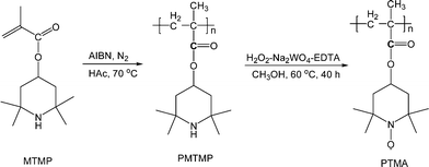 | ||
| Scheme 1 Synthesis of PTMA. | ||
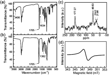 | ||
| Fig. 1 IR spectra of (a) MTMP and (b) PTMA, (c) solid state 13C NMR of PTMA, (d) ESR of PTMA. | ||
Graphene oxide (GO) was synthesized according to the modified Hummer's method starting from graphite powders.48 GO was then reduced into graphene by heating for 2 h at 900 °C under 25% H2–Ar atmosphere. The structures of pristine graphite, as-synthesized GO, and graphene were characterized by the X-ray diffraction (XRD) patterns (ESI†, Fig. S2). After the oxidation of graphite to GO, the high-intensity diffraction peak of (002) plane shifts to low angle. However, the diffraction peak shifts back to higher angle with a significant broadening after the H2–Ar reduction of GO to graphene. The XRD results are similar to the previous reported.49 The as-prepared graphene was dispersed in N-methylpyrollidinone (NMP) solvent for the preparation of electrodes.
The PTMA/graphene composite materials were prepared through a dispersing–depositing process (ESI†). SEM image (Fig. S3 in ESI†) and TEM image (Fig. S4 in ESI†) show that the composite is a nanocomposite, while the XRD pattern (Fig. S5 in ESI†) indicates that the nanocomposite is an amorphous material. When added into the solution, the graphene layers were impregnated with the soluble PTMAvia the force of absorption and capillarity. During the solvent vaporization, the PTMA deposited gradually and adhered on the surface of graphene. Meanwhile, the continuous stirring was helpful to form a homogeneous distribution.
Electrochemical tests were performed on pristine PTMA and PTMA/graphene composite by using lithium metal as the negative electrode. The ratio of active electrode material was the same as previously reported in the literature.28Fig. 2a shows the cyclic voltammogram (CV) curves of the PTMA electrode between 2.0 and 4.0 V at a scan rate of 0.1 mV s−1. Two pairs of chemically reversible redox peaks were observed. The first pair of peaks is in the range of 2.8–3.0 V, corresponding to the redox reaction between the PTMA radical and aminoxy anion (n-type doped state). The second pair of peaks is at around 3.6 V, attributed to the redox reaction between the PTMA radical and oxoammonium cation (p-type doped state) (Scheme 2). In addition, the reduction peak at 2.2 V is irreversible due to the irreversible reaction. The two-electron redox reaction behavior of PTMA is similar to that of DNA linked TEMPO complexes.31
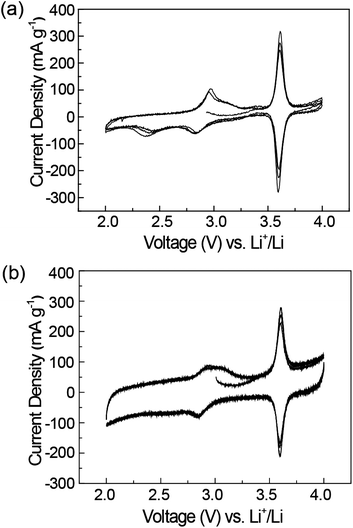 | ||
| Fig. 2 Cyclic voltammograms for (a) PTMA, and (b) PTMA/graphene electrodes. | ||
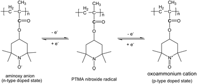 | ||
| Scheme 2 Redox couples of PTMA. | ||
Fig. 2b shows that the PTMA/graphene composite exhibits a rectangular shape except for the two pairs of redox peaks, indicating the supercapacitance contribution from graphene and carbon black.
Fig. 3a shows the charge–discharge profiles of the initial 3 cycles for PTMA at a rate of 1 C (completing the discharge or charge process in 1 h). During the first charge process of PTMA, voltage increases from the open voltage of 3.0 V to 3.5 V, followed by a plateau at 3.6 V, and finally increases to a top cutoff voltage of 4.0 V. The initial charge capacity is up to 120 mA h g−1. During the discharge process, the voltage quickly reduces from 4.0 to 3.7 V, followed by a plateau at about 3.6 V. Then the voltage decreases to 2.8 V, followed by another plateau at about 2.5–2.8 V, and then gradually decreases to a bottom cutoff voltage at 2.0 V. The first discharge capacity finally reaches 166 mA h g−1. It is remarkable that two voltage plateaus at 2.5–3.2 V and 3.5–3.7 V display in the second charge/discharge process of PTMA. In addition, the discharge voltage plateau at 2.3 V is irreversible. Fig. 3b shows the charge-discharge profiles of the initial 3 cycles for PTMA/graphene composite at a rate of 1 C. Similar to PTMA, the charge-discharge profiles also have two voltage plateaus at 2.5–3.2 V and 3.5–3.7 V. Note that the charge capacity is 250 mA h g−1 and the discharge capacity is up to 222 mA h g−1 in the 3rd cycle, which is about double the theoretical capacity of PTMA based on one electron redox reaction,28,29 and indicating a two-electron process.
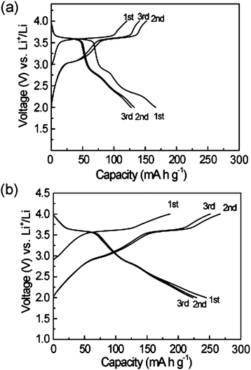 | ||
| Fig. 3 The charge-discharge profiles of the initial three cycles at a rate of 1 C for (a) PTMA, and (b) PTMA/graphene. | ||
It should be mentioned that the discharge curve becomes sloped between 2.3 V and 2.0 V, which might be ascribed to the contribution from the non-faradic reaction of ion sorption/desorption on the graphene and carbon black, and is consistent with the rectangular shape as shown in above CV curves (Fig. 2b). In order to clarify the capacity contribution from graphene and carbon black, the charge-discharge voltage profiles were measured and the results are shown in Fig. S6 in the ESI.† It is found that the specific capacity of graphene and carbon black is only 20 mA h g−1 in the voltage range of 2.0 and 4.0 V, which is much lower than that of PTMA. The charge/discharge curves of PTMA/graphene composite appeared to be similar from the 2nd to the 3rd cycle, indicating that the PTMA/graphene composite possesses stable charge/discharge properties and good cycle performance. It can be concluded that, for the PTMA/graphene composite, the first charge process at the 3.6 V plateau corresponds to the oxidation of PTMA to oxoammonium cation, and the discharge process is the two-stage reduction of oxoammonium cation to radical, followed to aminoxy anion. The second charge process begins from aminoxy anion to oxoammonium cation with a charge capacity at the 2nd stage of about 266 mA h g−1, and the specific capacity is slightly reduced during the 2nd to the 3rd cycles. The PTMA/graphene composite exhibits a two-stage redox reaction from an anion via a radical to a cation, in which the two-electron processes results in a high capacity of 222 mA h g−1 promoted by graphene. These results are also in good accordance with those results from above CV tests. After 100 cycles, the reversible capacities of PTMA/graphene composite and PTMA remain 169 and 76 mA h g−1 at a rate of 1 C (Fig. 4a).
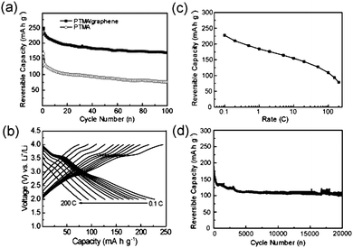 | ||
| Fig. 4 Rate capability and cycle performance of PTMA/graphene. (a) Reversible capacity vs. cycle number at 1 C. (b) Galvanostatic charge-discharge curves at different rates from 0.1 C to 200 C. (c) Plots of reversible capacity vs. rate. (d) Cycle performance at 100 C. | ||
The rate-capability of PTMA/graphene composite was further evaluated at different rates from 0.1 C to 200 C. The reversible capacities shown in Fig. 4b, 4c represent the remaining capacities after 50 cycles. It can be seen that the capacities decrease slowly with the increase of charge-discharge rates. The reversible capacity is about 226 mA h g−1 at a rate of 0.1 C, and about 80 mA h g−1 even at a high rate of 200 C (completing the charge or discharge process in about 18 s), suggesting an outstanding rate capability of the PTMA/graphene composite. Fig. 4d illustrates the cycle performance of the PTMA/graphene composite at a high rate of 100 C in a voltage range of 2.0–4.0 V. The cell could maintain a high capacity of 100 mA h g−1 even after 20![[thin space (1/6-em)]](https://www.rsc.org/images/entities/char_2009.gif) 000 cycles. These results demonstrate that the PTMA/graphene composite has an excellent rate performance and an ultra-long cycle life. While the former is related with the fast electrode reaction of radical polymer with the help of unlimited electron transportvia the 3D network of graphene, the latter could be attributed to the good chemical and structure stability of the radical polymer of PTMA.29
000 cycles. These results demonstrate that the PTMA/graphene composite has an excellent rate performance and an ultra-long cycle life. While the former is related with the fast electrode reaction of radical polymer with the help of unlimited electron transportvia the 3D network of graphene, the latter could be attributed to the good chemical and structure stability of the radical polymer of PTMA.29
In summary, we have developed a simple method to synthesis PTMA/graphene composite in which the graphene serves as the electronic conductivity support. The PTMA/graphene composite exhibits a two-electron reaction process and reversible two-stage charge/discharge processes. The composite shows a reversible capacity of up to 222 mA h g−1 at 1 C, and a ultra-long cycle life of more than 20![[thin space (1/6-em)]](https://www.rsc.org/images/entities/char_2009.gif) 000 cycles at 100 C. In view of its excellent rate performance and long cycle life, the PTMA/graphene composite promises a good application in electrochemical energy storage devices. The results here also give clear evidence of the utility of graphene to improve the electrochemical performance of radical polymers as electrode materials for lithium-ion batteries. The strategy is simple, yet very effective, and because of its versatility could also be extended to other radical polymers used in lithium-ion batteries.50,51
000 cycles at 100 C. In view of its excellent rate performance and long cycle life, the PTMA/graphene composite promises a good application in electrochemical energy storage devices. The results here also give clear evidence of the utility of graphene to improve the electrochemical performance of radical polymers as electrode materials for lithium-ion batteries. The strategy is simple, yet very effective, and because of its versatility could also be extended to other radical polymers used in lithium-ion batteries.50,51
Acknowledgements
We gratefully thank the National Basic Research Program of China (Grant Nos. 2011CB935700 and 2009CB930400), the National Natural Science Foundation of China (Grant Nos. 20821003, 21073205 and 50730005), and the Chinese Academy of Sciences for financial support.Notes and references
- A. S. Arico, P. Bruce, B. Scrosati, J. M. Tarascon and W. Van Schalkwijk, Nat. Mater., 2005, 4, 366–377 CrossRef CAS.
- J. Maier, Nat. Mater., 2005, 4, 805–815 CrossRef CAS.
- Y. G. Guo, J. S. Hu and L. J. Wan, Adv. Mater., 2008, 20, 2878–2887 CrossRef CAS.
- P. G. Bruce, B. Scrosati and J. M. Tarascon, Angew. Chem., Int. Ed., 2008, 47, 2930–2946 CrossRef CAS.
- C.-X. Zu and H. Li, Energy Environ. Sci., 2011, 4, 2614–2624 CAS.
- V. Etacheri, R. Marom, R. Elazari, G. Salitra and D. Aurbach, Energy Environ. Sci., 2011, 4, 3243–3262 CAS.
- H. Li, Z. X. Wang, L. Q. Chen and X. J. Huang, Adv. Mater., 2009, 21, 4593–4607 CrossRef CAS.
- X. L. Wu, L. Y. Jiang, F. F. Cao, Y. G. Guo and L. J. Wan, Adv. Mater., 2009, 21, 2710–2714 CrossRef CAS.
- J. W. Fergus, J. Power Sources, 2010, 195, 939–954 CrossRef CAS.
- X. X. Li, F. Y. Cheng, B. Guo and J. Chen, J. Phys. Chem. B, 2005, 109, 14017–14024 CrossRef CAS.
- G. Z. Wei, X. Lu, F. S. Ke, L. Huang, J. T. Li, Z. X. Wang, Z. Y. Zhou and S. G. Sun, Adv. Mater., 2010, 22, 4364–4367 CrossRef CAS.
- O. K. Park, Y. Cho, S. Lee, H.-C. Yoo, H.-K. Song and J. Cho, Energy Environ. Sci., 2011, 4, 1621–1633 CAS.
- J. M. Tarascon, Philos. Trans. R. Soc. London, Ser. A, 2010, 368, 3227–3241 CrossRef.
- M. Armand and J. M. Tarascon, Nature, 2008, 451, 652–657 CrossRef CAS.
- H. Chen, M. Armand, G. Demailly, F. Dolhem, P. Poizot and J. M. Tarascon, ChemSusChem, 2008, 1, 348–355 CrossRef CAS.
- J. K. Feng, Y. L. Cao, X. P. Ai and H. X. Yang, J. Power Sources, 2008, 177, 199–204 CrossRef CAS.
- P. Poizot and F. Dolhem, Energy Environ. Sci., 2011, 4, 2003–2019 CAS.
- X. P. Gao and H. X. Yang, Energy Environ. Sci., 2010, 3, 174–189 CAS.
- P. Novák, K. Müller, K. S. V. Santhanam and O. Hass, Chem. Rev., 1997, 97, 207–281 CrossRef.
- Z. P. Song, H. Zhan and Y. H. Zhou, Angew. Chem., Int. Ed., 2010, 49, 8444–8448 CrossRef CAS.
- N. Oyama, T. Tatsuma, T. Sato and T. Sotomura, Nature, 1995, 373, 598–600 CrossRef CAS.
- M. Yao, H. Senoh, S. I. Yamazaki, Z. Siroma, T. Sakai and K. Yasuda, J. Power Sources, 2010, 195, 8336–8340 CrossRef CAS.
- X. Han, C. Chang, L. Yuan, T. Sun and J. Sun, Adv. Mater., 2007, 19, 1616–1621 CrossRef CAS.
- T. L. Gall, K. H. Reiman, M. C. Grossel and J. R. Owen, J. Power Sources, 2003, 119–121, 316–320 CrossRef.
- R.-H. Zeng, X.-P. Li, Y.-C. Qiu, W.-S. Li, J. Yi, D.-S. Lu, C.-L. Tan and M.-Q. Xu, Electrochem. Commun., 2010, 12, 1253–1256 CrossRef CAS.
- T. Suga, H. Ohshiro, S. Sugita, K. Qyaizu and H. Nishide, Adv. Mater., 2009, 21, 1627–1630 CrossRef CAS.
- K. Qyaizu and H. Nishide, Adv. Mater., 2009, 21, 2339–2344 CrossRef.
- K. Nakahara, S. Iwasa, M. Satoh, Y. Morioka, J. Iriyama, M. Suguro and E. Hasegawa, Chem. Phys. Lett., 2002, 359, 351–354 CrossRef CAS.
- J.-K. Kim, J.-H. Ahn, G. Cheruvally, G. S. Chauhan, J.-W. Choi, D.-S. Kim, H.-J. Ahn, S. H. Lee and C. E. Song, Met. Mater. Int., 2009, 15, 77–82 CrossRef CAS.
- Y. Wang, P. He and H. Zhou, Energy Environ. Sci., 2011, 4, 805–817 CAS.
- J. Qu, R. Morita, M. Satoh, J. Wada, F. Terakura, K. Mizoguchi, N. Ogata and T. Masuda, Chem.–Eur. J., 2008, 14, 3250–3259 CrossRef CAS.
- K. Nakahara, J. Iriyama, S. Iwasa, M. Suguro, M. Satoh and E. J. Cairns, J. Power Sources, 2007, 165, 870–873 CrossRef CAS.
- J.-K. Kim, G. Cheruvally, J.-H. Ahn, Y.-G. Seo, D. S. Choi, S.-H. Lee and C. E. Song, J. Ind. Eng. Chem., 2008, 14, 371–376 CrossRef CAS.
- S. Komaba, T. Tanaka, T. Ozeki, T. Taki, H. Watanabe and H. Tachikawa, J. Power Sources, 2010, 195, 6212–6217 CrossRef CAS.
- R. Zhao, L. Zhu and H. Yang, Prog. Chem., 2011, 23, 302–309 CAS.
- F. Ding, H. Ji, Y. Chen, A. Herklotz, K. Dörr, Y. Mei, A. Rastelli and O. G. Schmidt, Nano Lett., 2010, 10, 3453–3458 CrossRef CAS.
- S. Stankovich, D. A. Dikin, G. H. B. Dommett, K. M. Kohlhaas, E. J. Zimney, E. A. Stach, R. D. Piner, S. T. Nguyen and R. S. Ruoff, Nature, 2006, 442, 282–286 CrossRef CAS.
- S. Yang, X. Feng, L. Wang, K. Tang, J. Maier and K. Müllen, Angew. Chem., Int. Ed., 2010, 49, 4795–4799 CAS.
- C. N. R. Rao, A. K. Sood, K. S. Subrahmanyam and A. Govindaraj, Angew. Chem., Int. Ed., 2009, 48, 7752–7777 CrossRef CAS.
- B. Z. Jang and A. Zhamu, J. Mater. Sci., 2008, 43, 5092–5101 CrossRef CAS.
- F. F. Cao, Y. G. Guo and L. J. Wan, Energy Environ. Sci., 2011, 4, 1634–1642 CAS.
- L. S. Zhang, L. Y. Jiang, H. J. Yan, W. D. Wang, W. Wang, W. G. Song, Y. G. Guo and L. J. Wan, J. Mater. Chem., 2010, 20, 5462–5467 RSC.
- B. Wang, X. L. Wu, C. Y. Shu, Y. G. Guo and C. R. Wang, J. Mater. Chem., 2010, 20, 10661–10664 RSC.
- H. Wang, L.-F. Cui, Y. Yang, H. S. Casalongue, J. T. Robinson, Y. Liang, Y. Cui and H. Dai, J. Am. Chem. Soc., 2010, 132, 13978–13980 CrossRef CAS.
- J. Zhu, Y. K. Sharma, Z. Zeng, X. Zhang, M. Srinivasan, S. Mhaisalkar, H. Zhang, H. H. Hng and Q. Yan, J. Phys. Chem. C, 2011, 115, 8400–8406 CAS.
- S. Yang, G. Cui, S. Pang, Q. Cao, U. Kolb, X. Feng, J. Maier and K. Müllen, ChemSusChem, 2010, 3, 236–239 CrossRef CAS.
- Y. Sun, Q. Wu and G. Shi, Energy Environ. Sci., 2011, 4, 1113–1132 CAS.
- W. S. Hummers, Jr and R. E. Offeman, J. Am. Chem. Soc., 1958, 80, 1339 CrossRef.
- A. V. Murugan, T. Muraliganth and A. Manthiram, Chem. Mater., 2009, 21, 5004–5006 CrossRef CAS.
- K. Koshika, N. Sano, K. Oyaizu and H. Nishide, Chem. Commun., 2009, 836–838 RSC.
- T. Suga, H. Konishi and H. Nishide, Chem. Commun., 2007, 1730–1732 RSC.
Footnotes |
| † Electronic supplementary information (ESI) available: Experimental details, TGA result of PTMA; XRD patterns of pristine graphite, as-synthesized graphite oxide, graphene, and PTMA/graphene composite; SEM and TEM image of PTMA/graphene composite, charge-discharge voltage profiles of graphene and carbon black. See DOI: 10.1039/c1ee02148f |
| ‡ Also at the Graduate School of CAS, Beijing, 100064, P. R. China. |
| This journal is © The Royal Society of Chemistry 2012 |
