One-pot green hydrothermal synthesis of CuO–Cu2O–Cu nanorod-decorated reduced graphene oxide composites and their application in photocurrent generation†
Jingqi
Tian
ab,
Haiyan
Li
a,
Zhicai
Xing
a,
Lei
Wang
a,
Yonglan
Luo
a,
Abdullah M.
Asiri
cd,
Abdulrahman O.
Al-Youbi
cd and
Xuping
Sun
*acd
aState Key Lab of Electroanalytical Chemistry, Changchun Institute of Applied Chemistry, Chinese Academy of Sciences, Changchun, 130022 Jilin, China. E-mail: sunxp@ciac.jl.cn; Fax: +86-431-85262065; Tel: +86-431-85262065
bGraduate School of the Chinese Academy of Sciences, Beijing 100039, China
cChemistry Department, Faculty of Science, King Abdulaziz University, Jeddah 21589, Saudi Arabia
dCenter of Excellence for Advanced Materials Research, King Abdulaziz University, Jeddah 21589, Saudi Arabia
First published on 9th August 2012
Abstract
In this communication, we develop a facile one-pot green strategy toward CuO–Cu2O–Cu nanorod-decorated reduced graphene oxide (CuNRs–rGO) composites by hydrothermal heating of the mixed solution of GO and Cu(OAc)2 under basic conditions without the use of extra reducing agents. As-synthesized composites have been successfully applied in photocurrent generation in the visible spectral region.
Graphene, a flat monolayer of sp2-bonded carbon atoms tightly packed into a two-dimensional (2D) honeycomb lattice, has received tremendous attention due to its high surface area (∼2600 m2 g−1), high chemical stability, unique electronic and mechanical properties.1 Among the various exciting characteristics, the superior electrical conductivity and mechanical properties make graphene an excellent material for collecting and transporting charge in photocatalysis.2 Recently, much efforts have been made in preparing graphene-based composites to increase the efficiency of photocatalysis and solar cells,3 in which graphene serves as a scaffold to anchor metal or semiconductor nanoparticles and assists in promoting selectivity and efficiency of the catalytic process.4
Cu and its oxides have also attracted a great deal of attention because of their various applications. CuO has been widely used in many important fields such as gas sensors, magnetic phase transitions, superconductors and photocatalysts.5 Cu2O, a p-type semiconductor with particular optical and magnetic properties, has also been applied in a series of fields such as solar energy conversion, electronics, magnetic storage, photocatalytic water splitting and gas sensors.6 Cu is usually found in both fundamental research and technical applications.7 Inspired by enhancement of the properties of nanoparticles through anchoring them onto reduced graphene oxide (rGO), researchers have attempted to prepare Cu or its oxides decorated rGO. Till now, many synthetic methods have been developed,8 including direct mixing of the pre-synthesized Cu nanowires and graphene to fabricate Cu-nanowire-doped graphene,8a heating an aqueous solution of Cu salts in the presence of graphene synthesized by an arc discharge method to synthesize CuO–graphene,8b solvothermal synthesis of CuO–GO and the subsequent reduction of GO by hydrothermal reaction,8c nanocrystal-seed-directed hydrothermal synthesis of CuO–G–CuO heterostructures,8d decorating CuO on the functionalized hydrogen induced exfoliated graphene (f-HEG) followed by a chemical reduction process to form CuO–HEG,8e chemical vapor deposition of graphene on the Cu substrate,8f synthesis of CuO–rGO by heating the mixture of Cu salts and GO in the presence of poly[(2-ethyldimethylammonioethyl methacrylate ethyl sulfate)-co-(1-vinylpyrrolidone)] and urea,8getc. Unfortunately, these methods suffer from the involvement of two steps in the preparation or the use of toxic or hazardous reducing agents such as N,N-dimethylformamide (DMF), NaBH4, urea and easily burning H2 in the reaction, posing environmental and health risks. Cu2O–graphene have also been prepared by a one-pot solvothermal8h or a one-step solution-phase8i method; however, this system suffers from the involvement of an extra reducing agent such as ethylene glycol or glucose. Although the synthesis of Cu or its oxides decorated rGO has been intensively explored, to the best of our knowledge, no attention has been paid to synthesizing multicomponent Cu and its oxides decorated rGO so far.
In this communication, we develop a facile green strategy toward one-pot hydrothermal synthesis of CuO–Cu2O–Cu nanorod-decorated rGO (CuNRs–rGO) for the first time. The formation of the composites is accomplished by direct hydrothermal heating of the mixed solution of GO and Cu(OAc)2 under basic conditions at 180 °C for 3 h without the extra introduction of other reducing agents. We further demonstrate the successful application of such composites in photocurrent generation in the visible spectral region of white light.
Fig. 1 shows the UV-vis spectra of aqueous dispersion of GO and the product thus formed. As excepted, GO exhibits strong bands centered at 230 and 300 nm, corresponding to π–π* transitions of the aromatic C![[double bond, length as m-dash]](https://www.rsc.org/images/entities/char_e001.gif) C band and n–π* transitions of the C
C band and n–π* transitions of the C![[double bond, length as m-dash]](https://www.rsc.org/images/entities/char_e001.gif) O band in GO, respectively. It is clearly seen that the adsorption peak at 230 nm disappeared and a new broad absorption band at around 400 nm appeared after the hydrothermal treatment, indicating the reduction of GO and that the product is capable of absorbing visible light. The inset of Fig. 1 shows the corresponding photographs, indicating a distinct color change from pale-yellow to black after reaction.
O band in GO, respectively. It is clearly seen that the adsorption peak at 230 nm disappeared and a new broad absorption band at around 400 nm appeared after the hydrothermal treatment, indicating the reduction of GO and that the product is capable of absorbing visible light. The inset of Fig. 1 shows the corresponding photographs, indicating a distinct color change from pale-yellow to black after reaction.
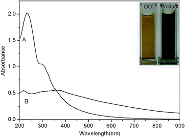 | ||
| Fig. 1 UV-vis absorption spectra of aqueous dispersion of GO (A) and the product thus obtained (B). Inset shows the corresponding photographs. | ||
Fig. 2 shows the Raman spectra of GO and the product thus formed. It is reported that graphene obtained by chemical reduction of GO exhibits two characteristic main peaks: the D band at ∼1350 cm−1, arising from a breathing mode of κ-point photons of A1g symmetry; the G band at 1575 cm−1, corresponding to the first order scattering of the E2g phonon of sp2 C atoms.9 In our study, it is seen that both GO and the product exhibit a D band at 1355 cm−1 and a G band at 1596 cm−1. The product is also found to show relatively higher intensity of the D to the G band (0.93) than that of GO (0.80). These observations confirm the formation of new graphitic domains after the reaction.
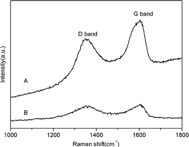 | ||
| Fig. 2 Raman spectra of GO (A) and the product thus obtained (B). | ||
The XRD pattern of the product is shown in Fig. 3. The peaks located at 32.5°, 35.5°, 38.7°, 48.8°, 53.4°, 58.3°, 61.6°, 66.2°, 68.1° and 75.2° are assigned to 110, 002, 111, ![[2 with combining macron]](https://www.rsc.org/images/entities/char_0032_0304.gif) 02, 020, 202,
02, 020, 202, ![[1 with combining macron]](https://www.rsc.org/images/entities/char_0031_0304.gif) 13,
13, ![[3 with combining macron]](https://www.rsc.org/images/entities/char_0033_0304.gif) 11, 220 and
11, 220 and ![[2 with combining macron]](https://www.rsc.org/images/entities/char_0032_0304.gif) 22 faces of CuO, which are consistent with the standard reported values (JCPDS File no. 05-0661), demonstrating the formation of CuO.10 The peaks located at 29.7°, 36.5° and 42.4° correspond to the reflections from 200, 211 and 220 planes of Cu2O, which are consistent with the standard reported values (JCPDS File no. 02-1067), demonstrating the formation of Cu2O.11 In addition, the two peaks centered at 43.3° and 50.4° can be assigned to the 111 and 200 planes of metallic copper, indicating the formation of metallic Cu.12 The broad peak observed at 2θ = 20–30° indicates the disordered stacking of rGO sheets.13 All these observations indicate the formation of CuO, Cu2O, and Cu. The mass percentage of CuO, Cu2O, and Cu was estimated to be 45%, 48% and 7%, respectively.
22 faces of CuO, which are consistent with the standard reported values (JCPDS File no. 05-0661), demonstrating the formation of CuO.10 The peaks located at 29.7°, 36.5° and 42.4° correspond to the reflections from 200, 211 and 220 planes of Cu2O, which are consistent with the standard reported values (JCPDS File no. 02-1067), demonstrating the formation of Cu2O.11 In addition, the two peaks centered at 43.3° and 50.4° can be assigned to the 111 and 200 planes of metallic copper, indicating the formation of metallic Cu.12 The broad peak observed at 2θ = 20–30° indicates the disordered stacking of rGO sheets.13 All these observations indicate the formation of CuO, Cu2O, and Cu. The mass percentage of CuO, Cu2O, and Cu was estimated to be 45%, 48% and 7%, respectively.
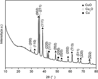 | ||
| Fig. 3 XRD pattern of the product thus obtained. | ||
Fig. 4A shows the typical TEM images of the product, suggesting that a large amount of nanorods with a length of 100 to 500 nm and a width of 20 to 50 nm are formed on the surface of rGO sheets. The chemical composition of the product was further determined by the energy-dispersed spectrum (EDS), as shown in Fig. 4B. The peaks of C, Cu, and O elements are observed, indicating that the composites are formed from copper salt and GO. All these observations confirm the successful synthesis of CuO–Cu2O–Cu nanorod-decorated rGO composites.
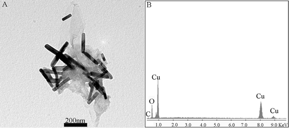 | ||
| Fig. 4 Typical TEM image (A) and the corresponding EDS (B) of the product thus obtained. | ||
It is well known that nanocatalysis is a very exciting and promising field in nanomaterials and nanochemistry and the properties of nanomaterials will be affected by size, morphology and other factors. For example, Pan et al. have confirmed that both the particle size of CuO and the oxidation state of Cu play vital roles in the catalytic process.14 The influence of GO on the morphology of Cu and its oxides in the present system was investigated. It is found that the absence of GO in this system yields irregular particles of several micrometers in size (Fig. S1, ESI†), which were labeled CuMPs. Such an observation suggests that GO is key to the formation of nanorods, but the exact mechanism is not clear at present time. Furthermore, the composition of thus obtained CuMPs was characterized by XRD, which is shown in Fig. S2 (ESI†), demonstrating that the CuMPs are comprised of CuO.11
Huaman et al. have reported that the addition of NaOH to the alcohol solution of Cu2+ salts under heat treatment results in the formation CuO, Cu2O, and Cu.15 It is also established that NaOH is capable of accelerating the reduction of copper oxide due to the formation of a hydroxo complex of copper.15,16 GO is covered with hydroxyl groups on the hexagonal basal plane17 and can serve as a mild reducing agent. Indeed, it is confirmed that GO can reduce Ag+ under basic conditions.18 In our present study, NaOH not only reacts with Cu2+ leading to CuO, but also accelerates the partial reduction of CuO into Cu2O and further to Cu under hydrothermal conditions. It is of importance to note that the absence of GO only gives CuO, suggesting that GO serves as a reducing agent for CuO. On the other hand, GO is converted into rGO rapidly under alkaline conditions.19 As a result, CuO–Cu2O–Cu nanorod-decorated rGO was formed finally.
We further explored the application of the composites for photocurrent generation in the visible range of light. The transient photocurrents of rGO, CuMPs, and CuNRs–rGO irradiated with visible light (λ > 400 nm) are shown in Fig. 5. For rGO, a small anodic photocurrent ca. 0.04 μA in intensity is obtained under visible light illumination (Fig. 5A). For CuMPs, a cathodic photocurrent (0.11 μA) is obtained under visible light illumination (Fig. 5B), which can be attributed to the ability of the CuMPs to absorb visible light, indicating that the photogenerated electrons move to the outer surface and leave holes in the bulk. In contrast, when irradiated with visible light, a cathodic photocurrent is observed for CuNRs–rGO and the photocurrent intensity is about 0.23 μA, exhibiting a 2-fold enhancement with CuMPs (Fig. 5C). This is mainly because both CuO and Cu2O in the composites are semiconductors with a narrow band gap, which is 1.2 eV and 2.0 eV, respectively.20 It is also seen from Fig. 5C that when the light was on, a cathodic sharp spike photocurrent appeared immediately, followed by the generation of an anodic sharp spike photocurrent. This phenomenon can be attributed to the faster photocurrent generation of rGO than that of CuNRs21 and then the rapid recombination of photogenerated electrons and holes in the composites. Although the anodic photocurrent was offset by the cathodic photocurrent generated by rGO, the enhancement in photocurrent intensity for CuNRs–rGO indicates that the photoresponse has been improved by rGO in the composites, as shown in Scheme 1. Thus we come to the conclusion that rGO has a positive role in the photocurrent generation of the modified electrode. On one hand, rGO can accept the electrons from the CuNRs; on the other hand, rGO can facilitate electrons transfer within the composite film.22
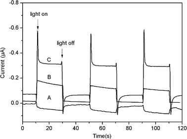 | ||
| Fig. 5 Photocurrent responses of rGO (A), CuMPs (B) and CuNRs–rGO (C) modified ITO electrodes in a standard three-compartment cell along with a Pt wire counter electrode and a reference electrode (Ag/AgCl) under white light illumination (λ > 400 nm; input power, 100 mW cm−2; electrolyte, 1 M Na2SO4 aqueous solution; electrode potential of 0 V vs. Ag/AgCl). | ||
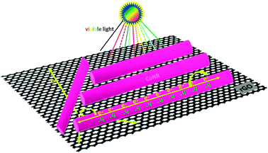 | ||
| Scheme 1 Schematic diagram illustrating the photogenerated charge transport in the CuNRs–rGO composites. | ||
In summary, hydrothermal heating of the mixed solution of GO and Cu(OAc)2 in the presence of sodium hydroxide has been proven to be an effective strategy toward one-pot green preparation of CuNRs–rGO without the use of other reducing agents. The application of such CuNRs–rGO in photocurrent generation has also been demonstrated. Compared to CuMPs, the CuNRs–rGO composites show an enhancement in photocurrent. Our present study is significant because it provides us a practical, facile and green approach toward multicomponent graphene-based composites for energy and other applications.
Acknowledgements
This work was supported by the National Natural Science Foundation of China (No. 21175129), the National Basic Research Program of China (No. 2011CB935800), and the Scientific and Technological Development Plan Project of Jilin Province (No. 20100534 and 20110448).Notes and references
- (a) H. L. Guo, X. F. Wang, Q. Y. Qian, F. B. Wang and X. H. Xia, ACS Nano, 2009, 3, 2653 CrossRef CAS; (b) X. Huang, Z. Yin, S. Wu, X. Qi, Q. He, Q. Zhang, Q. Yan, F. Boey and H. Zhang, Small, 2011, 7, 1876 CrossRef CAS; (c) S. Liu, J. Tian, L. Wang, H. Li, Y. Zhang and X. Sun, Macromolecules, 2010, 43, 10078 CrossRef CAS; (d) D. Li, M. B. Muller, S. Gilje, R. B. Kaner and G. G. Wallace, Nat. Nanotechnol., 2008, 3, 101 CrossRef CAS; (e) X. Huang, X. Y. Qi, F. Boey and H. Zhang, Chem. Soc. Rev., 2012, 41, 666 RSC; (f) A. K. Geim and K. S. Novoselov, Nat. Mater., 2007, 6, 183 CrossRef CAS; (g) J. Hass, W. A. de Heer and E. H. Conrad, J. Phys.: Condens. Matter, 2008, 20, 323202 CrossRef; (h) Q. Y. He, S. X. Wu, Z. Y. Yin and H. Zhang, Chem. Sci., 2012, 3, 1764 RSC.
- P. V. Kamat, J. Phys. Chem. Lett., 2011, 2, 242 CrossRef CAS.
- (a) H. Zhang, X. Lv, Y. Li, Y. Wang and J. Li, ACS Nano, 2009, 4, 380 CrossRef; (b) X. Zhang, H. Li, X. Cui and Y. Lin, J. Mater. Chem., 2010, 20, 2801 RSC; (c) N. Yang, J. Zhai, D. Wang, Y. Chen and L. Jiang, ACS Nano, 2010, 4, 887 CrossRef CAS.
- (a) G. Williams and P. V. Kamat, Langmuir, 2009, 25, 13869 CrossRef CAS; (b) G. Williams, B. Seger and P. V. Kamat, ACS Nano, 2008, 2, 1487 CrossRef CAS; (c) B. Seger and P. V. Kamat, J. Phys. Chem. C, 2009, 113, 7990 CrossRef CAS; (d) H. Li, S. Liu, J. Tian, L. Wang, W. Lu, Y. Luo, A. M. Asiri, A. O. Al-Youbi and X. Sun, ChemCatChem, 2012, 4, 1079 CrossRef CAS; (e) J. Tian, S. Liu, H. Li, L. Wang, Y. Zhang, Y. Luo, A. M. Asiri, A. O. Al-Youbi and X. Sun, RSC Adv., 2012, 2, 1318 RSC.
- (a) C. D. Cavellin and M. Lagues, Nature, 2001, 414, 434 CrossRef; (b) L. C. Jiang and W. D. Zhang, Biosens. Bioelectron., 2010, 25, 1402 CrossRef CAS; (c) S. Gao, S. Yang, J. Shu, S. Zhang, Z. Li and K. Jiang, J. Phys. Chem. C, 2008, 112, 19324 CrossRef CAS; (d) M. J. Song, S. W. Hwang and D. Whang, Talanta, 2010, 80, 1648 CrossRef CAS; (e) H. Yu, J. Yu, S. Liu and S. Mann, Chem. Mater., 2007, 19, 4327 CrossRef CAS.
- (a) W. Wang, G. Wang, X. Wang, Y. Zhan, Y. Liu and C. Zheng, Adv. Mater., 2002, 14, 67 CrossRef CAS; (b) L. Gou and C. J. Murphy, Nano Lett., 2003, 3, 231 CrossRef CAS; (c) R. Liu, F. Oba, E. W. Bohannan, F. Ernst and J. A. Switzer, Chem. Mater., 2003, 15, 4882 CrossRef CAS; (d) C. Lu, L. Qi, J. Yang, X. Wang, D. Zhang, J. Xie and J. Ma, Adv. Mater., 2005, 17, 2562 CrossRef CAS; (e) J. T. Zhang, J. F. Liu, Q. Peng, X. Wang and Y. D. Li, Chem. Mater., 2006, 18, 867 CrossRef CAS; (f) L. Huang, F. Peng, H. Yu and H. Wang, Solid State Sci., 2009, 11, 129 CrossRef CAS; (g) S. X. Wu, Z. Y. Yin, Q. Y. He, G. Lu, X. Z. Zhou and H. Zhang, J. Mater. Chem., 2011, 21, 3467 RSC; (h) S. X. Wu, Z. Y. Yin, Q. Y. He, X. Huang, X. Z. Zhou and H. Zhang, J. Phys. Chem. C, 2010, 114, 11816 CrossRef CAS.
- (a) X. Wang, F. Zhang, B. Xia, X. Zhu, J. Chen, S. Qiu, P. Zhang and J. Li, Solid State Sci., 2009, 11, 655 CrossRef CAS; (b) S. X. Wu, Z. Y. Yin, Q. Y. He, G. Lu, Q. Y. Yan and H. Zhang, J. Phys. Chem. C, 2011, 115, 15973 CrossRef CAS.
- (a) J. Liang, H. Bi, D. Wan and F. Huang, Adv. Funct. Mater., 2012, 22, 1267 CrossRef CAS; (b) B. Wang, X.-L. Wu, C.-Y. Shu, Y.-G. Guo and C.-R. Wang, J. Mater. Chem., 2010, 20, 10661 RSC; (c) Y. J. Mai, X. L. Wang, J. Y. Xiang, Y. Q. Qiao, D. Zhang, C. D. Gu and J. P. Tu, Electrochim. Acta, 2011, 56, 2306 CrossRef CAS; (d) R. J. Zou, Z. Y. Zhang, L. Yu, Q. W. Tian, Z. G. Chen and J. Q. Hu, Chem.–Eur. J., 2011, 17, 13912 CrossRef CAS; (e) T. T. Baby and R. Sundara, J. Phys. Chem. C, 2011, 115, 8527 CrossRef CAS; (f) Y. Qi, J. R. Eskelsen, U. Mazur and K. W. Hipps, Langmuir, 2012, 18, 3489 CrossRef; (g) S. Liu, J. Q. Tian, L. Wang, Y. L. Luo and X. P. Sun, Catal. Sci. Technol., 2012, 2, 339 RSC; (h) F. Zhang, Y. Li, Y. Gu, Z. Wang and C. Wang, Microchim. Acta, 2011, 173, 103 CrossRef CAS; (i) B. Li, H. Cao, G. Yin, Y. Lu and J. Yin, J. Mater. Chem., 2011, 21, 10645 RSC.
- Y. Guo, S. Guo, J. Ren, Y. Zhai, S. Dong and E. Wang, ACS Nano, 2010, 4, 4001 CrossRef CAS.
- C. Yan, L. Zou, D. Xue, J. Xu and M. Liu, J. Mater. Sci., 2008, 43, 2263 CrossRef CAS.
- (a) A. N. Tsvigunov, L. A. Frolova and V. G. Khotin, Glass Ceram., 2003, 60, 9 CrossRef; (b) V. G. Pol, D. N. Srivastava, O. Palchik, V. Palchik, M. A. Slifkin, A. M. Weiss and A. Gedanken, Langmuir, 2002, 18, 3352 CrossRef CAS.
- Z. Zhang and P. Wang, J. Mater. Chem., 2012, 22, 2456 RSC.
- (a) Y. Yang, L. Ren, C. Zhang, S. Huang and T. Liu, ACS Appl. Mater. Interfaces, 2011, 3, 2779 CrossRef CAS; (b) E. H. L. Falcao, R. G. Blair, J. J. Mack, L. M. Viculis, C. W. Kwon, M. Bendikov, R. B. Kaner, B. S. Dunn and F. Wudl, Carbon, 2007, 45, 1367 CrossRef CAS; (c) H. P. Cong, J. J. He, Y. Lu and S. H. Yu, Small, 2010, 6, 169 CrossRef CAS; (d) V. Chandra, J. Park, Y. Chun, J. W. Lee, I. Hwang and K. S. Kim, ACS Nano, 2010, 4, 3979 CrossRef CAS.
- K. Pan, H. Ming, H. Yu, Z. Kang, H. Zhang and S. Lee, Cryst. Res. Technol., 2011, 11, 1167 CrossRef.
- J. L. C. Huaman, K. Sato, S. Kurita, T. Matsumoto and B. Jeyadevan, J. Mater. Chem., 2011, 21, 7062 RSC.
- S. Sun, C. Kong, D. Deng, X. Song, B. Ding and Z. Yang, CrystEngComm, 2011, 13, 63 RSC.
- P. R. Kannan, A. Swami, D. Srisathiyanarayanan, P. S. Shirude, R. Pasricha, A. B. Mandale and M. Sastry, Langmuir, 2004, 20, 7825 CrossRef.
- (a) R. Pasricha, S. Gupta and A. K. Srivastava, Small, 2009, 5, 2253 CrossRef CAS; (b) J. Tian, S. Liu, Y. Zhang, H. Li, L. Wang, Y. Luo, A. M. Asiri, A. O. Al-Youbi and X. Sun, Inorg. Chem., 2012, 51, 4742 CrossRef CAS.
- X. Fan, W. Peng, Y. Li, X. Li, S. Wang, G. Zhang and F. Zhang, Adv. Mater., 2008, 20, 4490 CrossRef CAS.
- (a) A. E. Rakhshani, Solid-State Electron., 1986, 29, 7 CrossRef CAS; (b) W. Siripala, R. D. L. D. Perera, K. T. L. De Silva, J. K. D. S. Jayanetti and I. M. Dharmadasa, Sol. Energy Mater. Sol. Cells, 1996, 44, 251 CrossRef CAS.
- C. Chao, W. Cai, M. Long, B. Zhou, Y. Wu, D. Wu and Y. Feng, ACS Nano, 2010, 4, 6425 CrossRef.
- H. I. Hayashi, V. Lightcap, M. Tsujimoto, M. Takano, T. Umeyama, P. V. Kamat and H. Imahori, J. Am. Chem. Soc., 2011, 133, 7684 CrossRef CAS.
Footnote |
| † Electronic supplementary information (ESI) available. See DOI: 10.1039/c2cy20406a |
| This journal is © The Royal Society of Chemistry 2012 |
