Nanoconfinement of Ni clusters towards a high sintering resistance of steam methane reforming catalysts†
Roya
Dehghan-Niri
a,
John C.
Walmsley
*ab,
Anders
Holmen
c,
Paul A.
Midgley
d,
Erlying
Rytter
e,
Anh Hoang
Dam
c,
Ana B.
Hungria
df,
Juan C.
Hernandez-Garrido
df and
De
Chen
*c
aDepartment of Physics, Norwegian University of Science and Technology (NTNU), Hogskoleringen 5, 7491, Trondheim, Norway
bSINTEF Materials and Chemistry, Hogskoleringen 5, 7491, Trondheim, Norway. E-mail: John.Walmsley@sintef.no
cDepartment of Chemical Engineering, Norwegian University of Science and Technology (NTNU), Sem Sælands vei 4, Trondheim, Norway. E-mail: chen@nt.ntnu.no; Fax: +47 73595047; Tel: +47 48222428
dDepartment of Materials Science and Metallurgy, University of Cambridge, Pembroke Street, CB23QZ, Cambridge, UK
eStatoil R&D, Research centre, Postuttak, NO-7005 Trondheim, Norway
fDepartamento de Ciencia de los Materials, Ingenieria Metalurgicay Quimica Inorganica, Facultad de Ciencias, Universidad de Cadiz, Rio San Pedro s/n, Puerto Real, 11510, Spain
First published on 2nd August 2012
Abstract
This study reports an improvement of the stability of steam reforming catalysts at relatively low temperatures, such as for pre-reforming, and reforming of biomass derived compounds, by enhanced stabilization of Ni nanoparticles through spatial confinement in a mixed oxides matrix. We revealed a simple approach of three dimensional engineering of Ni particles by means of self-assembly of Ni atoms inside the nanoribbon of hydrotalcite-derived mixed oxides. Taking advantage of Transmission Electron Microscopy (TEM), together with electron tomography, the three dimensional (3D) structure of the catalyst was investigated at a nanometer scale, including the Ni particle size, shape, location and spatial distribution, as well as pore size and morphology of the mixed oxides. Porous nano-ribbons were formed by high temperature treatment, adopting the layer structure of the hydrotalcite-like materials. Ni particles formed by selective reduction of mixed oxides embedded in the nano-ribbons with connected pore channels, allowing good access for the reactants. These spatially confined and well distributed Ni particles increased catalyst stability significantly compared to the Ni particles supported on the support surfaces in a commercial catalyst during the steam methane reforming.
Introduction
Rational design of catalysts has played an increasing role in the development of new catalysts and radical improvements of the existing industrial catalysts.1 In addition to the surface composition, particle size and, shape of nanoparticles, the hierarchical structure of the catalysts has an important implication for catalytic activity, selectivity and stability.2,3 Great efforts have been devoted to design catalysts with a high stability without compromising high activity. Steam methane reforming is the most promising reaction for synthesis gas production, which is of great importance for large scale production of methanol, ammonia, and hydrogen.4,5 The Ni catalyst is still a preferred selection as the industrial catalyst due to its relatively low price and high abundance. Ni is also a typical catalyst for pre-reforming, which is conventionally used to convert heavy hydrocarbons to methane and syngas at relatively low temperatures to reduce the coking potential during steam reforming at high temperatures.6,7 In addition, Ni catalysts have drawn increasing attention for hydrogen production from biomass derived compounds at relatively low temperatures.8 However, there has long been a challenge to increase the resistance to carbon formation and sintering of the Ni catalysts. Enormous efforts have been made in the fundamental investigation of surface elementary reaction steps, including carbon formation, effects of the surface composition and the Ni particles size on the activity and stability.9–17 These fundamental insights make it possible to rationally design Ni based catalysts with respect to high activity, high resistances to carbon formation and sintering,11,16,18 which are essential for the reforming reactions at relatively low temperatures, such as pre-reforming and reforming of biomass derived compounds. Manipulating the surface composition is a prevalent principle in rational catalyst design to reduce surface carbon concentration by reducing the methane decomposition rate.16,18 However, the most promising strategy to achieve a high carbon resistance but without compromising high activity is to use Ni nanoparticles with smaller size.17 As a consequence, the greatest challenge is how to stabilize the Ni nanoparticles at relatively high temperatures in the presence of steam.Conventional metal nanoparticles are typically deposited on the surface of the supports and sintering is unavoidable at high temperatures due to their mobility. Approaches involving embedded catalysts, where the small metal particles are isolated by the porous support shell, have shown promising potential in suppressing sintering of the metal effectively. The porous structure of the support shell ensures the access of reactant molecules to the active sites.3 Several approaches have been employed to isolate individual nanoparticles, such as embedding in sol–gel matrices and metal@support core–shell catalysts.3 In addition high hydrothermal stability of the support is a strong requirement for steam reforming catalysts. Spinels, such as MgAl2O4 and CaAl2O4, have long been used as the industrial catalyst supports, due to their high stability and mechanical strength. Moreover, high Ni activity requires highly porous catalysts with a relatively large pore size to reduce mass transport resistance. However, it remains a challenge to prepare small sized Ni nanoparticles isolated in a highly stable, suitable porous support.
Hydrotalcite-derived materials have long been used as sorbents and catalysts.19–21 The general formula for hydrotalcite (HT) materials is:
| [Mn2+Mm3+(OH)2(n+m)]m+Am/xx−·yH2O | (1) |
It is demonstrated that the hydrotalcite-derived Ni catalysts possess a superior activity and stability with respect to a commercial reforming Ni catalysts. The hydrotalcite-derived Ni catalysts provide small Ni particles, high resistance to carbon formation and excellent stability.9,23 However, a detailed understanding of the catalyst structure and properties responsible for such superior catalytic performance is still missing. Here we combine Transmission Electron Microscopy (TEM) and High Angle Annular Dark Field (HAADF) Scanning TEM (STEM) imaging to study the development of the structure, including three dimensional structures of pores, Ni or Ni oxide particle size, shape and distribution in each treatment step starting from the hydrotalcite like materials. Taking advantage of electron tomography in heterogeneous catalysts and related nanomaterials,24–29 we reveal for the first time that the three dimensional structure of the porous oxide ribbons, where the individual Ni particles were isolated by the oxide shell, makes them stable. These new fundamental insights provide prevalent principles in rational catalyst design of nanomaterials highly stable at high temperatures.
Experimental procedure
Catalyst preparation and characterization
Hydrotalcite like materials containing Ni catalysts were prepared by co-precipitation of Mg(NO3)2·6H2O and Al(NO3)3·9H2O and Ni(NO3)2·6H2O to obtain the 12.5 wt% catalyst (12.5%Ni/HT), as described previously.9 The catalyst was dried overnight under vacuum at 343 K and calcined at 873 K for 6 h with a heating rate of 5 K min−1 in air. The materials were characterized by different techniques including TEM, chemisorption and X-ray diffraction (XRD). XRD spectra clearly indicate the pure structure of hydrotalcite of the synthesized catalyst, composed of 12.5 wt%Ni and the ratio of the Ni![[thin space (1/6-em)]](https://www.rsc.org/images/entities/char_2009.gif) :Mg:Al is 0.38:2.62:1.9
:Mg:Al is 0.38:2.62:1.9
A portion of the calcined sample was reduced in H2 flow (50% H2 in Ar) from 273 K to 943 K with a heating rate of 10 K min−1 and then kept for 10 hours. Passivation of the reduced Ni catalyst was performed at 305 K with 1% O2 in Ar before the ex-situ TEM characterization.
Transmission electron microscopy (TEM)
TEM samples were prepared by two different methods: dispersion and ultramicrotomy. In the first method, a dispersion of crushed catalysts powder in ethanol solvent is dried on a carbon support Cu mesh grid. For ultramicrotomy, a small amount of catalyst powder is embedded in a resin and stored overnight at room temperature. Thin uniform slices (∼50 nm thick) are then obtained by cutting the embedded catalyst with a diamond blade, using a commercial ultramicrotome. The slices are collected on a carbon support Cu mesh grid.Conventional TEM and STEM images were taken by a JEOL 2010F Field Emission Gun (FEG) instrument operating at 200 kV acceleration voltage. Electron tomography was used to reconstruct the three dimensional structure of the catalysts sample. Electron tomography series were acquired with a FEI Tecnai F20 FEG electron microscope operating at 200 kV. Tomographic acquisition of two dimensional images of the calcined and reduced 12.5%Ni/HT samples was performed in STEM mode over the tilt range of ±72°, with 2° increments, using a dedicated high-tilt sample holder. Image acquisition was undertaken using the FEI software package Xplore 3D. Alignment of the image stack and tomographic reconstructions were performed with FEI software package Inspect 3D using the Simultaneous Iterative Reconstructive Technique (SIRT) routine. Reconstructed volumes were then processed with ImageJ. Avizo6 software from Mercury Computer Systems was used to visualize the 3D data volume by the voltex view and segmentation. In the voltex view the re-projection of the 3D volume at each angle is produced from the intensity value of each voxel. In the segmentation method, the area of interest in the 3D volume is selected through the whole volume and visualized separately. Thresholding of feature edges was done manually within the visualization software.
Volumetric hydrogen chemisorption
Hydrogen adsorption of the Ni catalysts was measured at 308 K using a Micromeritics ASAP 2010C apparatus. The catalyst was loaded in a U-shaped quartz reactor heated by an electric furnace. The samples were initially evacuated at 308 K for one hour and then reduced in H2 flow at 943 K for 10 hours with a heating rate of 10 K min−1. After reduction, the samples were evacuated for 30 minutes at 943 K, followed by 60 minutes at 308 K. An adsorption isotherm was constructed at 308 K, based on the adsorbed amount of hydrogen at 10 different pressures in the range 4–310 mmHg. After pumping for 30 minutes, a second isotherm was measured in order to separate strongly and weakly bonded hydrogen. The difference between the two isotherms represents the chemisorbed amount of H2. The monolayer capacity was determined by extrapolating the linear part of the different isotherms to zero pressure.Nitrogen adsorption
Nitrogen adsorption–desorption isotherms for the Ni catalysts were performed using a CoulterTM SA 3100 instrument and the data were collected at liquid nitrogen temperature. Prior to the measurements the samples were dried under vacuum at 423 K for 1 h. The surface area was calculated from the Brunauer–Emmett–Teller (BET) equation and the total pore volume and the average pore size were calculated using the Barrett–Joyner–Halenda (BJH) method.30,31 BJH pore size distribution was estimated from the adsorption branch of the N2 adsorption isotherm, to avoid the possible tensile strength effect.32Catalyst testing
Catalysts activity and deactivation have been studied in a fixed-bed reactor at atmospheric pressure. 10 mg of the Ni catalyst diluted with 100 mg of inert α-Al2O3 was heated from ambient temperature to 943 K at 2 K min−1 in a mixture of 1:1 H2–Ar and held under these conditions for 10 h to reduce. The catalyst stabilized at 923 K, steam to carbon ratio: S/C = 3 and 50 cm3 min−1 of CH4. A total gas flow of 100 cm3 min−1 was obtained by using Ar and H2 as diluents.
Results
Properties of Ni catalysts
Fig. 1 shows the microstructural changes at different stages of the processing during the catalyst preparation. Fig. 1a shows that the synthesized materials have a compact structure of densely-packed, plate-shaped, crystals. Due to the overlapping of particles in the aggregate, the morphology of the individual particles is not obvious. Closer inspection reveals individual particles showing contrast that is consistent with the plate-like morphology that is expected for this material. Several examples are indicated by arrows. The uncalcined material was unstable under the electron beam and this prevented three dimensional analyses. After treatment at 873 K, XRD revealed that the hydrotalcite structure was transformed into mixed oxides, where the Ni–Mg–Al oxide solid solution is possibly formed, although MgO, NiO, Al2O3 and Ni–Mg oxide solid solutions could not be distinguished in the XRD spectra.9,17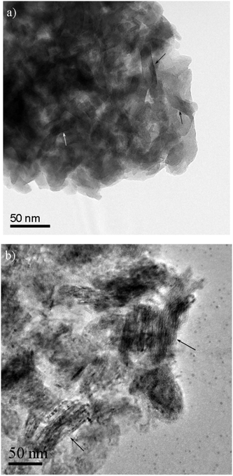 | ||
| Fig. 1 BF-TEM images of 12.5%Ni/HT, (a) before calcination and (b) after calcination, respectively. Likely plates, viewed approximately edge-on, are indicated in Fig. 1a. Particles where the layer structure is viewed approximately edge-on are indicated in Fig. 1b. | ||
The TEM image in Fig. 1b shows a more well-developed layered structure of the homogeneous mixed oxides than the hydrotalcite like material. The morphology of the calcined sample shows good contrast in the STEM images (Fig. 2a), in which contrast depends on the atomic number (Z). The dark areas are holes and the gray bright areas show the catalyst materials. The white contrast in Fig. 2a is due to the thickness of the sample.
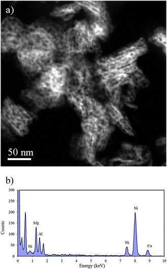 | ||
| Fig. 2 (a) A HAADF-STEM image of 12.5%Ni/HT after calcination, without reduction and (b) EDS spectrum of the calcined material. | ||
A layered ribbon structure is seen in the calcined material, which appears to be derived from the plate morphology of the hydrotalcite-like material. The morphology of the calcined material is described further in the next section. The length of the ribbons in the calcined material is larger than that of the original hydrotalcites, suggesting that a solid-state reaction occurred between the layered hydrotalcite like layers during calcination. More interestingly, the STEM image (Fig. 2a) reveals the rather characteristic pore structure of the ribbons in which the pores are roughly aligned in layers parallel to the ribbon surface. The calcination process obviously transforms the dense layer structure into the structure with a higher level of porosity and no obvious NiO particles are visible. The STEM contrast indicates that the Ni is homogeneously distributed in the oxide ribbons. Energy Dispersive Spectroscopy (EDS) analysis of several different positions in the sample gave Ni peaks with similar intensities relative to Mg and Al. Fig. 2b shows the EDS spectrum, which was taken from one of the examined areas similar to the one in Fig. 2a. The presence of strong Cu peaks is an artifact due to secondary fluorescence of the mesh grid used to support the carbon film.
By contrast, phase separation clearly occurred during the reduction and the Ni particles were formed from the mixed oxides. This is seen by comparing Fig. 2a and 3a. Fig. 3a is a STEM image of 12.5%Ni/HT after reduction.
 | ||
| Fig. 3 (a) A HADF STEM image of 12.5%Ni/HT after reduction treatment, and (b) EDS spectrum of a Ni particle indicated in Fig. 3a. | ||
The ribbons have smaller size after reduction. The Ni particles appear as bright features, which are embedded in the porous support and their composition was confirmed by EDS. The EDS spectrum in Fig. 3b was recorded from the Ni particle indicated in Fig. 3a, in which Ni has a peak with higher relative intensity than Mg and Al peaks which is seen in Fig. 2b, consistent with the particle being Ni surrounded by Mg/Al oxide.
The BET surface area was measured by N2 adsorption. Ni dispersion and Ni particle size were measured by H2 chemisorption and the results are summarized in Table 1. The properties of the commercial Ni catalyst supported on α-Al2O3 used as reference catalyst are also listed in Table 1. Both BET surface area and Ni dispersion are much higher for the hydrotalcite-derived catalyst, which results in a higher steam methane reforming activity than the commercial Ni catalyst. The catalyst stability was examined by the deactivation function 1 − r25/r0 (Table 1), where r0 and r25 are the reaction rates at 0 and 25 hours of the time on stream, respectively. Interestingly, the stability of the hydrotalcite-derived Ni catalysts is much better, as indicated by a much lower deactivation rate, than for the commercial Ni catalyst, although the Ni particle size is much smaller. Our previous results have indicated that a S/C of 3 is far beyond the coking threshold, and carbon formation should not be the cause of the deactivation.11 The improvement of stability of Ni catalysts derived form hydrotalcite like materials has been further evident from a comparative study between the hydrotalcite-derived Ni catalysts with several Ni loadings (12.5, 40 and 77.5) and the Ni (12 wt%) catalysts supported on hydrotalcite materials prepared by impregnation.9 A kinetic study also illustrated a much slower sintering kinetics of hydrotalcite-derived Ni catalysts compared to Ni supported on α-Al2O3 and CaAl2O4 spinels, although the Ni particles sizes are much larger on two late supports.17 Moreover, a large body of the literature has consistently shown a better stability of hydrotalcite-derived materials against heat treatment21,33–35 and good stability in steam reforming of ethanol.23
| Catalyst | BET (m2 gcat−1) | Ni surface area (m2 gcat−1) | Ni dispersion (%) | d Ni a (nm) | r 0 (mmol (gNi,s)−1) | Db (1 − r25/r0) |
|---|---|---|---|---|---|---|
| a Calculated from H2 chemisorption, dNi(nm) = 101/D(%), D: dispersion. b Deactivation rate at time on stream after 25 h where r0 is the initial activity and r25 is the activity measured at time on stream of 25 hours, steam reforming of CH4 at 923 K, 28.5 cm3 min−1 CH4, 20 cm3 min−1 H2, 5.1 g h−1 H2O, 9 cm3 min−1 Ar and 1 bar.9 c Commercial Ni catalyst, 12.5 wt% Ni/α-Al2O3. d BET surface area was measured on reduced and passivated 12.5%Ni/HT. | ||||||
| 12.5% Ni/HT | 229d | 9.1 | 11.4 | 8.9 | 7.8 | 0.04 |
| CCc | 5.5 | 1.3 | 1.5 | 65 | 2.4 | 0.51 |
Sintering has been identified as the main cause of the deactivation under the conditions studied.17 Both atomic and crystallite migration are important mechanisms for sintering.17,36 The better stability of the hydrotalcite-derived Ni catalysts could be ascribed to the different morphology and location of Ni particles in, or on, the supports (Fig. 3b) compared to the one on the commercial catalyst, studied in the calcined state, shown in Fig. 4. The large porous triangular shaped Ni particles were found on the blocky α-Al2O3 surfaces (Fig. 4) in the commercial Ni catalysts. Deposition of the metal particles on the support surfaces is the typical particle location for the conventional oxide supported catalysts prepared by impregnation. It is very different from the Ni particle location derived from hydrotalcite materials as shown in Fig. 3a, which will be analyzed by electron tomography in the next section.
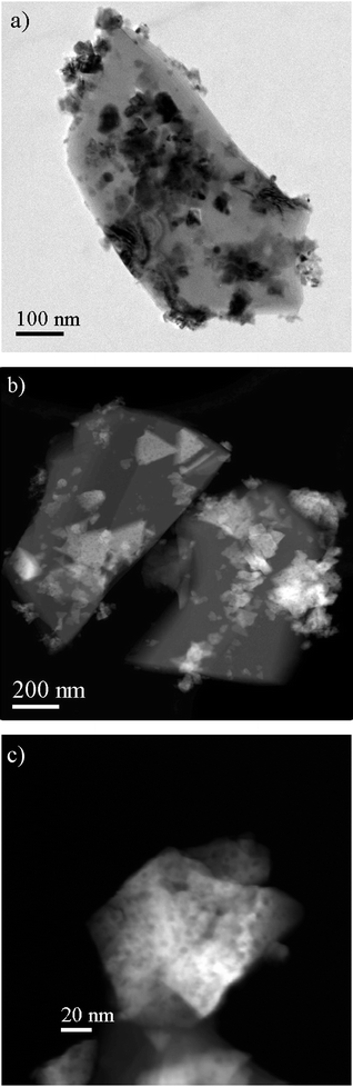 | ||
| Fig. 4 (a) BF-TEM and (b) HAADF-STEM images of a commercial Ni/α-Al2O3 catalyst. (c) STEM images showing porosity in Ni oxides. | ||
Three dimensional visualization analysis
For the hydrotalcite-derived catalyst, two dimensional images could not reveal the detailed three dimensional structures including pore structure and network, Ni particle size, shape and location and distribution in this embedded Ni catalysts. Electron tomography is applied to determine the three dimensional structure.Fig. 5a shows an orthoslice through a 3D reconstruction of the calcined material. Fig. 5b and c are snapshots of the voltex view of the same reconstruction from two different views. In Fig. 5b the reconstruction is tilted in a direction in which at least one ribbon is viewed edge-on, showing its thickness to be 15.8 nm. The average thickness of the ribbons in the analyzed volume was 15.2 ± 2.8 nm. In Fig. 5c the same ribbon is seen obliquely and shows much weaker contrast. The size of the rectangular ribbon marked in Fig. 5b is 12.4 nm × 51.5 nm × 15.8 nm. The results illustrate an interesting feature of the hydrotalcite-derived catalysts that the rather regular 3D nanometer-scale rectangular ribbon structure can be produced by the calcination of layered hydrotalcite structure. Moreover, Fig. 5 shows the arrangement of regular, small pores inside the ribbons. These internal pores have a roughly rectangular morphology and are regularly distributed within the plates. The internal pores with the average size of 4.3 ± 1.0 nm are formed parallel to the ribbon sheets. Besides the internal pores inside the structure of the catalyst, external pores are present in its microstructure which were formed in the junction of layered planes and generally have a larger size than the internal pores. An average external pore size was found to be 17.4 ± 5.1 nm.
 | ||
| Fig. 5 (a) An orthoslice through the 3D reconstructed series of calcined material, which shows the ordered porosity in the ribbons, (b) 3D voltex of the same reconstructed series, viewed in a direction in which one ribbon is viewed edge-on and (c) the same voltex rotated so that the same ribbon is viewed more obliquely. | ||
The dual pore size distribution obtained by electron tomography is consistent with the measurements of low temperature N2 adsorption, which is shown in Fig. 6. In this figure, two types of pores were identified, with average pore sizes of 2.8 nm and 18 nm, respectively. However, electron tomography provides also the pore structure and the location. There is a slight difference between the average small pore size measured by electron tomography and low temperature N2 adsorption techniques. The reason for this is believed to be that the resolution in the electron tomography series is not high enough to resolve the smallest pores in the structure and measure them accurately. However, these pores are observed in two dimensional TEM images and measurements of these images give the average of 3.5 ± 0.9 nm for the small pores, in agreement with low temperature N2 adsorption data.
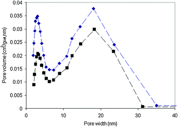 | ||
| Fig. 6 Pore size distribution of calcined (■) and reduced (◆) hydrotalcite-derived samples. | ||
The Ni nanoparticles location is shown in Fig. 7, where Fig. 7a shows an orthoslice of the 3D reconstructed series of the reduced materials and Fig. 7b is its voltex view. The bright features in Fig. 7 are Ni particles, which are located inside the oxide ribbon matrix. A movie of the voltex view of the reduced sample can be found in the supplementary information.†Fig. 7c and d show segmentation of the indicated Ni particle (yellow) and its surrounding oxides (red) from two different views. The morphology of the Ni nanoparticle without its surrounding is shown in Fig. 7e. A movie for segmentation of the Ni particle can be found in the supplementary information.† Segmentation shows that the Ni particle is embedded in the support structure but open channels are present, which makes it accessible to the reactant gases.
 | ||
| Fig. 7 (a) An orthoslice from the reconstructed series of reduced 12.5%Ni/HT, (b) a snapshot of the reconstruction in the voltex view in the same orientation, (c) and (d) segmented volume of the catalyst contains Ni (yellow) and its surrounding mixed oxides (red) in two different directions, (e) the segmented Ni particle showing its morphology. | ||
The Ni particles shape and 3D distribution are illustrated in Fig. 8, through segmentation of some of the Ni particles observed in the reconstructed series of the reduced sample, which is also shown in the movie in the supplementary information.†Fig. 8a shows the distribution of the Ni particles viewed from the x direction. Fig. 8b and c show the particles rotated for 20° and 40° relative to Fig. 8a, respectively. A few of the particles are labeled in each figure to make it easy to follow them after rotation. Fig. 8d and e show the morphology of a particle, P2, and Fig. 8f and g show the morphology of P3, in two different views. Both figures and movie show that most of the Ni particles are elongated in a direction along the ribbon axis and a few of them have a roughly spherical shape. All the Ni nanoparticles are constrained inside the rectangular ribbons.
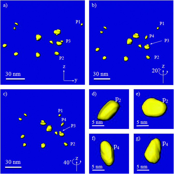 | ||
| Fig. 8 Segmentation of several particles in three different directions, (a) view parallel to the x direction, (b) rotated around z for 20°, (c) rotated around z for 40°, (d) and (e) showing the morphology of the particle 2, (P2), in two directions, and (f) and (g) showing the morphology of particle 4, (P4), in two directions. | ||
The catalyst particles are typically measured by hydrogen chemisorption, where metal particles are assumed to be of spherical shape. The Ni particle size of 8.9 nm measured by chemisorption is obviously only a mean size.
An attempt was made here to compare the mean size, which is estimated based on the 3D particle shape, to the one measured by chemisorption. Firstly, the size was measured in three directions for each particle, and the volume of each particle was estimated by assuming an ellipsoid shape. The mean size (2r) of Ni particles can then be estimated from the equivalent spherical volume with a radius as the volume measured. In this way, an average particle size of 7.5 ± 2.1 nm was obtained. The particle size measured on 2D images from several areas give an average of 8.9 ± 2.4 nm, which is similar to the Ni particle size measured by H2 chemisorptions, which was estimated by an assumption of ideal spherical Ni particles, Table 1. In the 2D particle size measurements of the oval shaped particles, the averages of maximum and minimum dimensions were considered. Since the measurements were made on several regions of the sample it is regarded as more reliable than the particle size from 3D visualization. It is interesting to note that the Ni particle size is larger than the pore size measured in the calcined samples. The pore size distributions in the calcined and reduced samples are unchanged. This is seen by the comparison of STEM images in Fig. 2a and 3a. The results from low temperature N2 adsorption in Fig. 6 confirm this, quantitatively. This indicates that the Ni particles nucleate and grow inside the oxide sheets, becoming enclosed in localized cages within the pore structure. This is consistent with the tomographic reconstruction of oxide ribbon sheets containing Ni particles.
Spatial confinement of Ni clusters and catalyst stability
Sintering is often the main cause of catalyst deactivation at high temperatures. Sintering occurs either through atomic migration from one crystallite to another, by diminishing small crystallites in size and increasing the larger ones, or via crystallite migration along the support surface, followed by collision and coalescence of two crystallites. The resistance to crystallite migration depends on the particle size and small sized crystals are mobile, thus having a low resistance for the migration.17,36,37 This leads to a great challenge in stabilization of nanoparticles at high temperatures. Industrial steam reforming catalysts typically use very large Ni particles supported on the low surface area of supports, as illustrated in Fig. 4. However, the particle migration resistance also depends on the support surface roughness, and maybe also the surface energy.37 The present work clearly illustrates that a large Ni particle size cannot guarantee the stability. The deactivation rate of Ni/α-Al2O3 (commercial catalysts) is still relatively high even though the Ni particle size is as high as 65 nm, Table 1.This study details a strategy for stabilizing the Ni nanoparticles through spatial confinement. The confinement is clearly demonstrated in Fig. 7c and d, where a Ni nanoparticle is confined inside a cage in porous ribbons (the segmented cube is 14 nm × 14 nm × 14 nm in size). In contrast to the deactivation of the large Ni particles on α-Al2O3, the confined catalyst is very stable during the steam methane reforming (Table 1). A very stable reaction rate with time on stream indicated a very little change in Ni dispersion. This suggests that the confinement of Ni particles increases the resistance for the crystal migration. Moreover, 3D volume measurements provide the distance between the closest neighboring Ni nanoparticles as shown in Fig. 8, which was determined to be 38 nm. The nanoconfined Ni nanoparticles and combined with a relatively long distance between adjacent particles provide a significant increase in the resistance to sintering, which results in a much lower deactivation rate compared to the commercial Ni catalyst, as indicated by a much lower deactivation function in Table 1. To find out more details of the catalyst stability with respect to sintering, it would be interesting to study the deactivated catalyst in 3D and compare it with the results from the fresh catalyst. This will be addressed in a future study.
Conclusions
The approach for improving the stability of the Ni nanoparticles catalyst for the steam reforming process, in particular under pre-reforming conditions, has been elucidated through nanoscale analysis. Three dimensional information of the structure of the catalyst was provided by electron tomography; the distribution, size, shape and location of the Ni nanoparticles were determined. In addition, the pore size, spatial shape and the thicknesses of the nano-ribbons in the Mg–Ni–Al mixed oxides substrate were measured. Good consistency between the results and the determined properties of the catalyst by chemisorption and low temperature N2 adsorption was observed. The combination of bulk property measurements and direct nanometer-scale observation is essential for an understanding of the structure at a nanometer level, providing a principle for rational design of the steam reforming catalysts towards a better stability, in particular for the steam reforming reactions at relatively low temperatures, such as pre-reforming and steam reforming of biomass derived compounds.8 The results reveal that rather regular rectangular shaped ribbons of Ni–Mg–Al mixed oxides were formed through calcination of layered hydrotalcites. The reduction resulted in the formation of Ni particles confined in the porous nano-ribbons of Mg–Al mixed oxides with connected pore channels which provided good catalyst stability and proper access for the gaseous reactants. Relatively long distances between the Ni particles further increase the resistance to crystal migration, and this may reduce the deactivation rate.Acknowledgements
The work is done through “NANOMAT and RENERGI Projects” financed by the Research Council of Norway and Statoil (NFR Project No. 169673/S10 and 178190). The financial support from the European Union under the Framework 6 program under a contract for an Integrated Infrastructure Initiative, Reference 026019 ESTEEM and financial support from the ERC under grant number 291523 3DIMAGE is greatly acknowledged.References
- J. H. Larsen and I. Chorkendorff, Surf. Sci. Rep., 1999, 35, 165–222 Search PubMed.
- G. A. Somorjai and J. Y. Park, Chem. Soc. Rev., 2008, 37, 2155–2162 RSC.
- C.-J. Jia and F. Schuth, Phys. Chem. Chem. Phys., 2011, 13, 2457–2487 RSC.
- J. R. Rostrup-Nielsen and R. Nielsen, Catal. Rev. Sci. Eng., 2004, 46, 247–270 CAS.
- J. R. Rostrup-Nielsen, J. Sehested and J. K. Norskov, in Advances in Catalysis, 2002, vol. 47, pp. 65–139 Search PubMed.
- T. S. Christensen, Appl. Catal., A, 1996, 138, 285–309 CrossRef CAS.
- T. Sperle, D. Chen, R. Lodeng and A. Holmen, Appl. Catal., A, 2005, 282, 195–204 CrossRef CAS.
- D. Chen and L. He, ChemCatChem, 2011, 3, 490–511 CrossRef CAS.
- E. Ochoa-Fernández, C. Lacalle-Vilà, K. Christensen, J. Walmsley, M. Rønning, A. Holmen and D. Chen, Top. Catal., 2007, 45, 3–8 CrossRef.
- H. S. Bengaard, J. K. Norskov, J. Sehested, B. S. Clausen, L. P. Nielsen, A. M. Molenbroek and J. R. Rostrup-Nielsen, J. Catal., 2002, 209, 365–384 CrossRef CAS.
- D. Chen, R. Lodeng, H. Svendsen and A. Holmen, Ind. Eng. Chem. Res., 2011, 50, 2600–2612 CrossRef CAS.
- D. W. Blaylock, T. Ogura, W. H. Green and G. J. O. Beran, J. Phys. Chem. C, 2009, 113, 4898–4908 CAS.
- F. Abild-Pedersen, J. K. Norskov, J. R. Rostrup-Nielsen, J. Sehested and S. Helveg, Phys. Rev. B: Condens. Matter Mater. Phys., 2006, 73 Search PubMed.
- F. Besenbacher, I. Chorkendorff, B. S. Clausen, B. Hammer, A. M. Molenbroek, J. K. Norskov and I. Stensgaard, Science, 1998, 279, 1913–1915 CrossRef CAS.
- D. Chen, K. O. Christensen, E. Ochoa-Fernandez, Z. X. Yu, B. Totdal, N. Latorre, A. Monzon and A. Holmen, J. Catal., 2005, 229, 82–96 CrossRef CAS.
- E. Nikolla, A. Holewinski, J. Schwank and S. Linic, J. Am. Chem. Soc., 2006, 128, 11354–11355 CrossRef CAS.
- K. O. Christensen, D. Chen, R. Lødeng and A. Holmen, Appl. Catal., A, 2006, 314, 9–22 CrossRef CAS.
- D. Chen, E. Bjørgum, R. Lødeng, K. Omdahl Christensen and A. Holmen, in Studies in Surface Science and Catalysis, ed. B. Xinhe and X. Yide, Elsevier, 2004, vol. 147, pp. 139–144 Search PubMed.
- S. Kannan, Catal. Surv. Asia, 2006, 10, 117–137 CrossRef CAS.
- M. R. Othman, Z. Helwani, Martunus and W. J. N. Fernando, Appl. Organomet. Chem., 2009, 23, 335–346 CrossRef CAS.
- K. Takehira and T. Shishido, Catal. Surv. Asia, 2007, 11, 1–30 CrossRef CAS.
- F. Cavani, F. Trifirò and A. Vaccari, Catal. Today, 1991, 11, 173–301 CrossRef CAS.
- L. He, H. Berntsen, E. Ochoa-Fernandez, J. C. Walmsley, E. A. Blekkan and D. Chen, Top. Catal., 2009, 52, 206–217 CrossRef CAS.
- P. A. Midgley, E. P. W. Ward, A. B. Hungria and J. M. Thomas, Chem. Soc. Rev., 2007, 36, 1477–1494 RSC.
- J. C. González, J. C. Hernández, M. López-Haro, E. del Río, J. J. Delgado, A. B. Hungría, S. Trasobares, S. Bernal, P. A. Midgley and J. J. Calvino, Angew. Chem., Int. Ed., 2009, 48, 5313–5315 CrossRef.
- K. P. de Jong and A. J. Koster, ChemPhysChem, 2002, 3, 776–780 CrossRef CAS.
- H. Friedrich, P. E. de Jongh, A. J. Verkleij and K. P. de Jong, Chem. Rev., 2009, 109, 1613–1629 CrossRef CAS.
- O. Ersen, J. Werckmann, M. Houllé, M.-J. Ledoux and C. Pham-Huu, Nano Lett., 2007, 7, 1898–1907 CrossRef CAS.
- J. M. Thomas and P. A. Midgley, Chem. Commun., 2004, 1253–1267 RSC.
- E. P. Barrett, L. G. Joyner and P. P. Halenda, J. Am. Chem. Soc., 1951, 73, 373–380 CrossRef CAS.
- S. Brunauer, P. H. Emmett and E. Teller, J. Am. Chem. Soc., 1938, 60, 309–319 CrossRef CAS.
- J. C. Groen, L. A. A. Peffer and J. Pérez-Ramírez, Microporous Mesoporous Mater., 2003, 60, 1–17 CrossRef CAS.
- Z. X. Yu, D. Chen, M. Ronning, B. Totdal, T. Vralstad, E. Ochoa-Fernandez and A. Holmen, Appl. Catal., A, 2008, 338, 147–158 CrossRef CAS.
- Z. X. Yu, D. Chen, M. Ronning, T. Vralstad, E. Ochoa-Fernandez and A. Holmen, Appl. Catal., A, 2008, 338, 136–146 CrossRef CAS.
- K. Takehira, J. Nat. Gas Chem., 2009, 18, 237–259 CrossRef CAS.
- C. H. Bartholomew, Appl. Catal., A, 1993, 107, 1–57 CrossRef CAS.
- E. Ruckenstein and D. B. Dadyburjor, J. Catal., 1977, 48, 73–86 CrossRef CAS.
Footnote |
| † Electronic supplementary information (ESI) available: Three supplementary videos included in this article show the visualized reconstruction of reduced 12.5%Ni/HT material, the segmented nanoparticle with surrounding mixed oxide and the segmentation of Ni nanoparticles. The content of movies is explained in the text. See DOI: 10.1039/c2cy20325a |
| This journal is © The Royal Society of Chemistry 2012 |