Mesostructured zeolite Y—high hydrothermal stability and superior FCC catalytic performance†
Javier
García-Martínez
*abc,
Marvin
Johnson
b,
Julia
Valla
b,
Kunhao
Li
b and
Jackie Y.
Ying
*cd
aMolecular Nanotechnology Laboratory, Inorganic Chemistry Department, University of Alicante, Campus de San Vicente, E-03690 Alicante, Spain. E-mail: j.garcia@ua.es
bRive Technology, Inc., 1 Deer Park Drive, Suite A, Monmouth Junction, NJ 08852, USA
cDepartment of Chemical Engineering, Massachusetts Institute of Technology, Cambridge, MA 02139, USA
dInstitute of Bioengineering and Nanotechnology, 31 Biopolis Way, The Nanos, Singapore 138669. E-mail: jyying@ibn.a-star.edu.sg
First published on 11th January 2012
Abstract
Controlled mesoporosity is successfully introduced into zeolite Y crystals through a surfactant templating approach. The mesoporous zeolite shows superb hydrothermal stability in the resulting mesostructure, while retaining strong acidity. Fluid catalytic cracking catalysts made from the mesostructured Y zeolites demonstrate significant improvement in product selectivity as a result of reduced limitation in reactant and product diffusion.
Introduction
Catalysis is probably one of the greatest contributions of chemistry to both economic growth and environmental protection.1 While 90% of the current chemical processes involve at least some catalytic steps,2 the field of catalytic materials still presents some major long-standing challenges, e.g. diffusion limitations of reactants and products within the porous structures of catalysts.3 Zeolites, the most widely used catalysts in industry,4 have micropores typically smaller than 1 nm, which limits the diffusion of compounds within these pores and the size of molecules that can be catalyzed.3–7 This issue has received increasing attention and research efforts have been devoted towards improving the internal pore accessibility by reducing the size of zeolite crystals8–13 or by synthesizing large-pore zeolites.14–18 The former strategy suffered from low yields and difficulty in handling nanometer-sized particles. Synthesis of zeolites with larger pore sizes has also received significant attention, but the high cost of these new materials has limited their potential applications.There has also been significant activity in the area of mesopore incorporation into zeolites. Two main approaches have been employed to impart mesoporosity to zeolites: (1) top-down techniques that involve the removal of one of the two main components of zeolites, i.e. silica (e.g. via desilication by treatment in alkaline solutions)19–23 or alumina (e.g. via dealumination by steaming at high temperatures or by chemical treatments),24–26 and (2) bottom-up procedures that utilize soft4,14,27–35 or hard13,36–41 templates (e.g. surfactants, inorganic sacrificial materials, etc.). The first is a destructive approach that often results in loss of zeolitic material. Other drawbacks of this approach may include: limited applicability due to materials composition (e.g. Si/Al ratio), poor control of the mesoporosity (e.g. size, shape, connectivity and location of the mesopores), etc. The second strategy is a convenient and versatile approach; however, the high cost of the templates may be a concern for large-scale applications. In addition, ordered mesoporous aluminosilicates have recently been prepared by assembling zeolite nanocrystals around surfactant micelles.42–45 These materials have much improved hydrothermal stability and acidity as compared to the amorphous mesoporous materials templated by the same surfactants. However, they are still inferior to zeolites in hydrothermal stability and acidity.
A technique that can introduce controlled mesoporosity directly into crystalline zeolites would be highly desirable and have a great impact on catalytic processes, such as fluid catalytic cracking (FCC).46 Herein, we describe a new surfactant-based technique that allows precisely controlled mesoporosity to be introduced within a wide range of zeolite crystals (i.e. mesostructuring), e.g. FAU, MOR and MFI of various Si/Al ratios, while maintaining the chemical and physical properties of the zeolites (i.e. microporosity, crystallinity, acidity, etc.).47
Experimental
Syntheses
In a typical synthesis, 1.00 g of a Y material (Zeolyst CBV720 with Si/Al = 15) in 64 mL of a 0.37 M solution of NH4OH containing 0.70 g of cetyltrimethyl ammonium bromide (CTAB) was stirred for 20 min. The mixture was next heated at 150 °C under autogenous pressure for 10 h. The solid was filtered, washed, and dried. Close to 100% recovery was observed, and there was no significant leaching of Si or Al species into the filtrate. Alternatively, other bases such as NaOH, Na2CO3 or tetrapropylammonium hydroxide (TPAOH) could be used. The pH of the reaction mixture was maintained at ∼9–11 to avoid desilication.To introduce mesoporosity into zeolite Y that has higher aluminium content (i.e. lower Si/Al ratio), e.g. Zeolyst CBV300, an acid wash pre-treatment step is needed. Typically, the zeolite slurry in water was treated with 1 mmol of citric acid per gram of zeolite (10% solution) for 1 hour. The acid treated material is then treated with the CTAB solution in NH4OH (or other bases such as NaOH, Na2CO3, etc.) to introduce mesoporosity. In order to remove the occluded templates, the dried product was heated in a nitrogen atmosphere from room temperature to 550 °C (at a ramping rate of ∼5 °C min−1), and kept at 550 °C for 2 hours. Next, the atmosphere was switched to air for 2 hours to remove any residual carbonaceous species. In order to convert the mesostructured NH4-Y (CBV300) sample to a typical USY, the rived sample (with template inside) was heated instead at 550 °C in 100% steam for 2 hours, followed by heating at 550 °C for another 2 hours in flowing air to remove any carbonaceous residue.
Characterization
The N2 or Ar adsorption–desorption isotherms were measured on Quadrasorb-SI surface area/pore size analyzers from Quantachrome Instruments. Samples were activated at 400 °C under vacuum overnight before measurements. A NLDFT model and a BJH model were used to obtain pore size distribution from the adsorption branches of the isotherms. X-Ray diffraction patterns were collected on a PANalytical Cubix Pro (PW3800) industrial X-ray diffractometer with a 1.8 kW Cu-target X-ray tube following ASTM D3942. Samples were hydrated inside a closed chamber with saturated CaCl2 aqueous solution overnight before analysis. Silicon powder was added as an internal standard. Additionally, temperature programmed ammonium desorption (TPAD) measurements were done on a TA Instrument Q50 TGA coupled with a Metrohm 857 Titrando automatic titrator. Samples were ammonium exchanged and dried before measurements.The microstructure and morphology of the materials were examined by transmission electron microscopy, TEM (JEM-2010 microscope, JEOL, 200 kV, 0.14 nm resolution) and scanning electron microscopy, SEM (JSM-840 microscope, JEOL). For TEM analysis, the as-obtained powder (5–10 mg) was sonicated in ethanol solution and the resulting suspensions were dispersed on carbon film supported 200 mesh copper grids. The digital analysis of the TEM micrographs was done using DigitalMicrograph TM 3.6.1 by Gatan. In some cases, samples were ultramicrotomed using a RMC MTX Ultramicrotome. Samples for SEM analysis were covered with gold for their observation. The XPS analysis of a mesostructured USY sample was performed by Anderson Materials Evaluation, Inc., Columbia, MD, over an elliptical area irradiated by the low energy (1487 eV) monochromatic aluminium Kα X-ray with a major axis of 1.2 mm and a minor axis of 0.6 mm (an area of approximately 0.6 mm2). The depth of the analyzed volume is about 8 nm, which is determined by the mean free path of the emitted photoelectrons. The elemental survey spectra cover the binding energy range from 0 to 1100 eV, with a step size of 0.5 eV. In order to investigate the chemical composition depth profile of the powder sample, the sample was sputtered by a focused ion beam sputter gun operating at 4 KeV with argon ions to an equivalent SiO2 sputter depth of 250 nm. 27Al MAS NMR spectra were obtained at Spectral Data Services, Inc., Champaign, IL, on a Tecmag-based system, operating at a 27Al frequency of 94.669 MHz, corresponding to H-1 frequency of 363.3 MHz. The FIDs were processed and deconvoluted using NUTS software (Acorn NMR). The IR spectra were collected at the Chemical Process Engineering Research Institute (CPERI) in Thessaloniki, Greece, on a Nicolet 5700 FTIR spectrometer (resolution 4 cm−1) using a MCT-A detector and a homemade stainless steel, vacuum cell, with CaF2 windows. Sample preparation consisted of fine self-supporting wafer formation and pretreatment in situ at 723 K under high vacuum (10−6 mbar) for 1 hour in order to remove any moisture and impurities.
Catalytic testing
The FCC catalysts were tested at the Technical Center of W. R. Grace & Company, Columbia, MD, using an ACE® unit from Xytel and Kayser Technologies. The ACE unit was an automated fluidized bed widely accepted in the FCC industry. The reactor was fluidized with a stream of nitrogen. In these studies, the feed is flown over the catalyst at a rate of 3.2 g min−1 over 30 s. Different amounts of the catalyst were fluidized and stabilized at a reaction temperature of 980 °F to achieve a different catalyst/oil ratio. After the reaction, the catalyst was stripped by nitrogen to remove the adsorbed products. Coke on the catalyst was determined by a carbon analyzer. Simulated distillation and on-line gas chromatography were used to determine the liquid and gaseous products, respectively. The feedstock used for the experiments was a VGO with API 24.7, CCR 0.32 wt%, sulfur 0.35 wt%, IBP 275 °C and FBP 682 °C.Results and discussions
The mesoporous zeolites thus prepared from CBV720 have high mesopore volumes and narrow mesopore size distributions (Fig. 1). N2 adsorption analysis showed that the mesostructured Y has a micropore volume (0–20 Å) of 0.21 cc g−1 and a mesopore volume (mainly in the 20–300 Å range) of 0.50 cc g−1, compared to 0.30 cc g−1 and 0.16 cc g−1 for the starting CBV720, respectively. The starting CBV720 has a BET surface area of 893 m2 g−1, of which 168 m2 g−1 is contributed by “external” surface area from t-plot analysis, i.e. surface areas from the true crystal external surfaces and from internal voids larger than micropores. The mesostructured Y exhibits a BET surface area of 1101 m2 g−1, ∼200 m2 g−1 higher than that of the starting material. More remarkably, 704 m2 g−1 is from the “external” surface for the mesostructured Y, about four times higher than that of the starting CBV720. This is believed to be directly related to the increased mesopore volume (0.50 cc g−1vs. 0.16 cc g−1) and the much more uniform size distribution of the mesopores around 40 Å in the mesostructured Y (Fig. 1). The size of these mesopores can be nicely controlled by using surfactant molecules of different lengths confirming the surfactant-templating mechanism proposed (ESI†, Fig. S2) as well as the mesopore architecture which can be controlled by adjusting the synthesis conditions to produce hexagonal ordering (ESI†, Fig. S3) at a higher degree of mesostructuring, or non-ordered mesoporosity (ESI†, Fig. S4) at a lower degree of mesostructuring. SEM and TEM images (Fig. 2 and ESI†, Fig. S1) revealed that the morphology of the zeolite crystals was maintained, and there was no sign of formation of separate amorphous mesoporous particles. Characteristic crystal lattice fringes and intracrystalline mesoporosity (holes) were clearly observed within the same crystal. This observation was recently confirmed in a different group by reproducing the same preparation described in our patent.48 It is also notable that most of the channels (of irregular shape and size) in the starting high Si/Al CBV720 zeolite (Fig. 2a, right), which have been generated due to the steaming dealumination process, disappeared after the treatment to introduce mesoporosity (Fig. 2b), which is corroborated by the reduction of the N2 uptake at high relative pressures (P/P0 > 0.9) after the material was treated by a solution of CTAB in NH4OH (Fig. 1).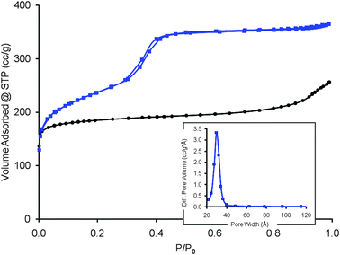 | ||
| Fig. 1 Nitrogen adsorption–desorption isotherms at 77 K for CBV720 (black circle) and the mesostructured CBV720 (blue square). The corresponding BJH pore size distribution of mesostructured CBV720 is shown in the inset. | ||
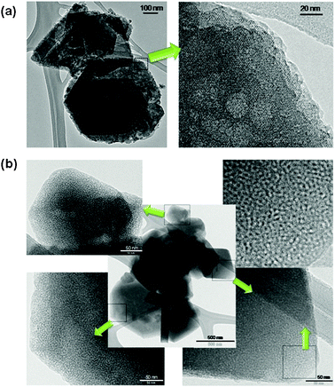 | ||
| Fig. 2 TEM images of (a) zeolite CBV720 and (b) mesostructured zeolite Y. The higher magnification micrographs of various mesostructured zeolite Y crystals clearly show intracrystalline mesoporosity and crystal lattices. | ||
The observations described above suggest that the introduction of controlled mesoporosity into crystalline zeolites proceeds possibly through a surfactant-assisted crystal rearrangement mechanism. Fig. 3 illustrates a plausible scheme of the critical steps in this process. Under the basic reaction conditions (pH ≈ 10.5), some of the Si–O–Si bonds are broken to offer some flexibility in the crystalline structure, and yield negatively charged sites in the zeolite framework that attract cationic surfactants. Electrostatic interactions between these negatively charged sites and the positively charged surfactants, and self-assembly of surfactant cations to form micelles within the zeolite crystals (so as to minimize the interaction of hydrophobic surfactant tails with the aqueous solution) cause the crystal structure to rearrange to form mesopores around the micelles. The whole process could be very dynamic and follow a mechanism similar to the cooperative formation of surfactant-templated mesoporous silicates4 except that in our materials the mesopores are formed in between crystalline pore walls.
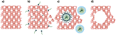 | ||
| Fig. 3 Schematic of the speculated zeolite mesopore formation process: (a) original zeolite Y, (b) Si–O–Si bond opening/reconstruction in basic media, (c) crystal rearrangement to accommodate the surfactant micelles, and (d) removal of the template to expose the mesoporosity introduced. | ||
There was no obvious change in the Si/Al ratio (the unit cell size, a0, stayed the same at ∼24.33 Å after the treatment) observed after the incorporation of mesoporosity, which suggested that no desilication occured under the mild basic conditions used. When CBV720 was treated under the same conditions but without base, no mesoporosity was generated, which suggested that it was the combination of cationic surfactant and mild basic conditions that allowed the structure rearrangement that was necessary in the formation of mesoporosity. This treatment has a product yield close to 100%, which was a significant advantage over destructive methods such as desilication. The role of the cationic surfactant was therefore critical because it protected the zeolite from desilication (as confirmed by control experiments with no surfactant), and allowed us to obtain much higher “hierarchy factors”22 and “desilication efficiency” (defined as external surface area developed per percent weight loss49), due to a more efficient preservation of microporosity. Moreover, the precise control over pore volume and size as well as pore architecture, thanks to the surfactant-assisted mesopore formation, was a clear advantage and a unique feature of mesostructured zeolites over hierarchical zeolites, a broader classification of zeolites with bimodal porosity.22
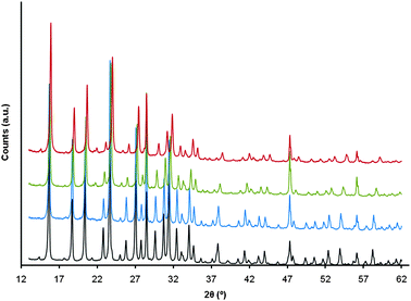
This discovery was made in 2004 and it was the first surfactant-templated mesoporous zeolite reported.50 However, this approach only worked for high silica content zeolites such as CBV720 (Si/Al = ∼15). Recently, significant progress has been made to extend this technique to zeolites with much higher alumina content (e.g. Na-Y, NH4-Y and USY of Si/Al ratio of 2.5–3), which are more relevant to oil cracking applications, specifically in FCC catalysis.51–53 Since Si–O–Al bonds are not as labile as the Si–O–Si under basic conditions, zeolites with higher aluminium content cannot undergo the proposed structure rearrangement to incorporate mesoporosity as in CBV720. An additional pre-treatment step of acid wash was introduced to the process to “loosen up” the crystalline structure of these zeolites with high aluminium contents.51 Careful pre-treatment of the zeolites with a dilute acid opened some of the Si–O–Al bonds with only minor dealumination of the zeolites (and thus slight increase in the bulk Si/Al ratio), without collapsing the crystalline structure. This was critical to extend the mesostructuring process to zeolites with high aluminium contents (with Si/Al as low as 2.5), which was deemed infeasible by other processes.54 X-ray diffraction of the acid-treated zeolite showed typical diffraction peaks for a Y zeolite with reduced peak intensity and broadened peak width (Fig. 4), suggesting the breakage of some of the O–Al bonds and formation of some defective sites (hydroxyl nests). There were slight shifts to higher angles for the peaks at ~ 54° and ~ 58° after the acid treatment. From the peak shifts, it was calculated that the unit cell size (a0) was reduced from 24.70 Å to 24.61 Å, suggesting slight dealumination by the citric acid (and consequently, formation of hydroxyl nests). The average FWHM (full width half max) of the two peaks also doubled from 0.16° to 0.32°, suggesting the introduction of defective sites by the acid treatment. The severity of this pre-treatment (e.g. amount of acid, time, temperature, etc.) could be fine-tuned to control the degree of dealumination and the amount of the mesoporosity that could be introduced in the subsequent treatment by surfactants in a basic media.
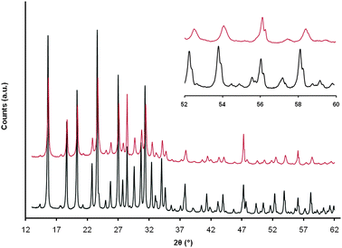 | ||
| Fig. 4 X-ray diffraction patterns of NH4-Y before (bottom) and after (top) acid pre-treatment. Inset: blow-up of the 52–60° range of the two diffraction patterns. | ||
Additional experimental evidence of the formation of hydroxyl nest defective sties during the acid pre-treatment step comes from the FT-IR analysis (Fig. 5). The analysis of the region between 3800–3500 cm−1 allows for the study of silanol terminal groups.55–57 In Y zeolites, the O–H stretch of silanol groups is typically observed at ∼3740 cm−1 and the O–H stretch of the strong Brønsted acid sites, i.e. Si–O(–H)–Al, is typically observed at ∼3640 cm−1. As one would expect, the initial material NH4-Y, after ammonia evacuation in situ at 723 K under high vacuum (10−6 mbar), shows a very intense peak at 3640 cm−1 due to strong Brønsted acidity with a negligible peak at 3740 cm−1 indicating a low concentration of silanol terminal groups at the external surface of the crystals. The IR spectrum changes significantly after the zeolite was washed with acid. Part of the Brønsted acidity was lost as the presence of silanol terminal groups increased; this was shown by the decrease in the intensity of the peak at 3640 cm−1 while the peak at 3740 cm−1 developed. This is consistent with the extraction of Al from the framework and the consequential formation of hydroxyl nests. More of these silanol terminal groups were formed when mesoporosity was introduced into the zeolite by caustic treatment in the presence of surfactant. The disappearance of Brønsted acid site O–H stretch at 3640 cm−1 was due to the treatment of the zeolite with NaOH that caused ion exchange of H+ with Na+. After NH4+ ion exchange, the peak reappeared (Fig. 5). The remaining peak at 3740 cm−1 corresponded to the terminal silanol groups on the mesopore surface.
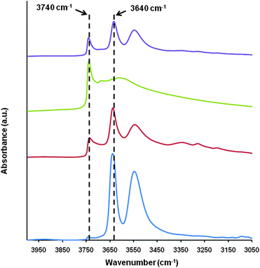 | ||
| Fig. 5 O–H stretch region of the FT-IR of, from bottom to top, the starting NH4-Y (CBV300), after citric acid pre-treatment, after treatment with CTAB in NaOH solution, after removal of template by calcination and NH4+ exchange. | ||
SEM and TEM (Fig. 6) analyses proved the formation of intracrystalline mesostructure similar to that shown in Fig. 2 and Fig. S1 (ESI†) for mesostructured CBV720. The TEM image of an ultramicrotomed sample (Fig. 6d) suggests that the mesopores penetrate deep into the crystals. From 27Al MAS-NMR analyses, it is noteworthy that only tetrahedrally coordinated Al with a chemical shift of ca. 60 ppm58–62 was observed in all the materials produced along the synthesis of mesostructured zeolite Y (Fig. 7). Octahedrally coordinated Al will typically give a peak at ∼0 ppm, which was not observed in any of these samples. The introduction of mesoporosity by basic treatment in the presence of CTAB caused slight broadening of the tetrahedral Al peak at 60 ppm, possibly due to the presence of distorted tetracoordinated Al (similar to those observed in the micro-mesoporous ZSM-5 prepared by carbon black templating63). The careful calcination of this sample in flowing N2 and then air to remove the surfactant produced a narrowing of the peak indicating that the heat treatment was enough to remove any distortions in the tetrahedral coordination of Al in the framework.
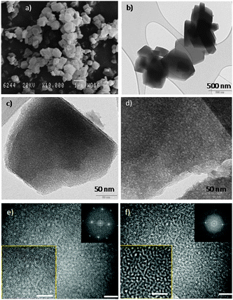 | ||
| Fig. 6 (a) SEM and (b–f) TEM images of the mesostructured Y zeolites. (c) A mesostructured zeolite single crystal showing crystalline lattice fringes and mesoporosity (holes). (d) An ultramicrotomed mesostructured zeolite crystal showing both crystallinity and mesoporosity. (e–f) Two TEM images of the same area of a mesostructured zeolite obtained at two different foci to better visualize the two features of this material: crystallinity and mesoporosity. The white scale bars represent 20 nm. | ||
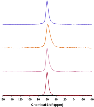 | ||
| Fig. 7 27Al MAS-NMR of, from bottom to top, the starting NH4-Y (CBV300), after citric acid pre-treatment, after treatment with CTAB in NaOH solution, after removal of template by calcination and NH4+ exchange. | ||
As to the mechanism of the formation of intracrystalline mesoporosity in zeolite Y with low Si/Al ratio, the experimental evidences described above are generally consistent with the mechanism described earlier for the high Si/Al Y zeolite such as CBV720. The acid pre-treatment extracts Al from the zeolite framework and introduces defects/hydroxyl nests that weaken the framework. In the subsequent basic reaction media, the silanol groups dissociate to form negatively charged SiO− sites that attract cationic surfactants. The surfactant molecules self-assemble to form micelles. It is speculated that the zeolite framework rearranges to accommodate these templates and thus forms the intracrystalline mesostructure. However, how exactly the rearrangement happens at the molecular level remains unclear.
It should be noted that the calcination condition used here is quite different from that used in the ultrastabilization described below. By carefully excluding any effect of water by flowing N2 through the samples when they were gradually heated to 550 °C, there was no extraframework Al species formed as evidenced by the NMR results. However, when the mesostructured NH4-Y was converted to a typical USY, water vapor was intentionally introduced in order to impart higher hydrothermal stability to the resulted material. This is a typical practice in Y zeolite manufacturing for FCC catalysis. It is well known that under such hydrothermal conditions, Y zeolite framework undergoes dramatic changes: framework Al species are expelled from tetrahedral positions to form extraframework Al species at the outer surface of the crystals, filling of some hydroxyl nests by Si atoms that leads to stabilization of the framework, migration and agglomeration of the other hydroxyl nests to form larger “holes” (which may appear in N2 or Ar adsorption analysis as meso-size “pores”), etc. XPS analysis of an ultrastabilized mesostructured NH4-Y (Table S2 in ESI†) revealed that the Si/Al ratio at the surface is lower than that at ∼250 nm equivalent SiO2 sputter depth, 3.0 vs. 3.4, suggesting that there was also formation and enrichment of extraframework Al species at the outer surface of the mesostructured Y zeolite. It is believed that these changes will cause interconnection and/or agglomeration of neighboring “rived” mesopores and lead to the broadening of the pore size distributions.
Fig. 8 shows the Ar adsorption isotherms and BJH pore size distributions of NH4-Y (Zeolyst CBV300, Si/Al = 2.55) as received and after being treated under similar conditions as described in the Experimental section, except that there was an acid wash pre-treatment, and that the NH4OH was replaced by NaOH. Significant mesoporosity (0.16 cc g−1; Table S1 in ESI†) was evidenced by the relatively sharp gas uptake at ca. 0.5 P/P0, which corresponded nicely to a mesopore size of ca. 40 Å, in accordance with the size of the surfactant micelles (CTAB). After converting to mesostructured USY by a typical ultrastabilization calcination, there was obvious broadening of the mesopore size distribution. Further broadening of the mesopore size distribution was noted upon treatment at 788 °C in pure steam for 4 h (this treatment is to simulate the typical deactivation of a Y zeolite inside an FCC unit). The inevitable (and to some degree, advantageous) change of pore size distribution is accompanied by reduction of mesopore surface area (ESI†, Table S1); however, it is notable that the mesopore volumes were maintained at ∼0.16 cc g−1 throughout these steps, confirming the excellent hydrothermal stability of the mesostructured zeolites.
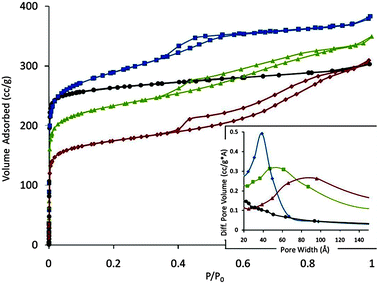 | ||
| Fig. 8 Ar adsorption isotherm of NH4-Y (black circle), mesostructured Y (blue square), and mesostructured USY before (green triangle) and after (red diamond) deactivation at 788 °C in 100% steam for 4 hours. The corresponding BJH pore size distributions of these samples are shown in the inset. | ||
The evolution of this sample was also monitored by X-ray diffraction (XRD) (Fig. 9 and Table S1, ESI†). After the incorporation of mesoporosity in the starting NH4-Y zeolite, the micropore volume was largely maintained (97%). After conversion to mesostructured zeolite USY by an ultrastabilization step, there was a decrease in micropore volume of ∼26%, which was comparable to that observed in conventional zeolite Y when ultrastabilized under the same conditions. Mesostructured USY did not show XRD peaks at low angles (2θ = 1–5°) as in the case of a highly mesostructured CBV720 (Fig. S3, ESI†), indicating that the mesopores were not ordered (Fig. S4, ESI†). After steaming at 788 °C for 4 h in 100% steam, the sample still showed very good retention of micropore volume (∼63% of that for the starting zeolite Y).
 | ||
| Fig. 9 XRD patterns of, from bottom to top, the starting NH4-Y (CBV300), mesostructured Y, and mesostructured USY, and after deactivation at 788 °C in 100% steam for 4 h. The intensities of the last three samples were corrected using a 1.45 empirical factor to account for the radiation absorption by the rare earth oxides (5 wt%) in these materials. | ||
The changes in the micropore volume of the mesostructured zeolite Y during the severe hydrothermal treatment steps described herein were similar in trend as those for conventional zeolite Y. The exceptional thermal and hydrothermal stabilities of the mesostructured zeolites prepared by the new technique were superior to those of the mesoporous silicates prepared by surfactant-templating methods.4,42–45,64 This could be attributed to the presence of intracrystalline mesoporosity, instead of X-ray amorphous mesoporosity. The preservation of zeolite crystallinity in the mesostructured zeolites enabled a high degree of hydrothermal stability, high micropore volume and strong acidity to be maintained in these new materials. Temperature programmed ammonium desorption (TPAD) measurements (Fig. S5, ESI†) revealed that the total acidity of the mesostructured USY is 1.18 milliequivalent H (meq. H) g−1, almost identical to that of conventional USY (CBV500, 1.25 meq. H g−1). These attractive characteristics are essential in the development of a successful catalyst for FCC applications.
Extensive catalytic testing of pure steam-deactivated samples for the catalytic cracking of a vacuum gas oil (VGO) was conducted in a microactivity unit (MAT). Fig. S6 (ESI†) shows the representative effect of the intracrystalline mesoporosity on the catalytic selectivity. Significant increase in the yields of gasoline and diesel (transportation fuels) and reduction in the yields of coke and dry gases were achieved with the steam-deactivated mesostructured USY zeolite as compared to conventional zeolites. The scalability of surfactant-assisted processes has been a question of wide interest.54 Preparation of mesostructured USY zeolites at multi kilogram (and even higher) quantity has been achieved using industrial equipment. The zeolites were also formulated in a wide variety of matrix compositions, including commercial silica and alumina sol matrices, into FCC microspheres (of ∼70 micron in size) using production-scale spray driers. The catalysts, after being properly deactivated (e.g. at 788 °C under 100% steam for 4 h) were tested on a fixed fluidized bed ACE testing unit with different feedstocks. Control catalysts were made with the same formulation using untreated zeolite USY and deactivated and tested following the same protocols. A typical comparison of the product selectivity is shown in Fig. 10 and Table S3 (ESI†). The catalysts made from mesostructured USY zeolites produced significantly more gasoline and light cycle oil (LCO), and less bottoms and coke. The much improved product selectivity could be attributed to the mesostructure introduced into the zeolites that eased the diffusion limitation in the conventional zeolites.65 The mesopores would allow larger molecules in the feedstock to access the acidic catalytic sites within the zeolite crystals, promoting the primary reactions to yield more gasoline and LCO. At the same time, the mesopores would also facilitate transport of the feed and the products into and out of the zeolite crystals more easily, thereby reducing the undesirable secondary reactions, i.e. over-cracking of the valuable gasoline and LCO to the low-value coke and dry gases. In addition, hydrogen transfer reaction, another secondary reaction, was also reduced, which explains the higher C3 and C4 olefin yields achieved with the new catalysts containing mesostructured zeolites.
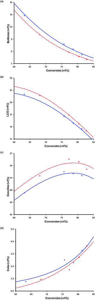 | ||
| Fig. 10 Catalyst evaluation of two FCC catalysts prepared and deactivated under the same conditions (788 °C in 100% steam for 8 h): one containing a conventional zeolite USY (blue diamond/solid line) and the other containing a mesostructured zeolite USY (red triangle/broken line). The catalyst evaluation was conducted in an ACE unit at 527 °C using a VGO feedstock (see Experimental). The lines were fitted by a kinetic lump model. | ||
Cost of the surfactant templates has been a concern for large-scale applications of the mesoporous materials prepared by this approach. Our estimates show that by proper recovery and recycle of the surfactants, the cost to the production of the mesoporous zeolite is incremental and well manageable. In a more recent development,66 we have also identified a new process that introduces similarly controlled mesoporosity into faujasite crystals without the use of surfactant templates. In-depth investigation is underway to better understand the material properties and catalytic performance, as well as details of the mechanism.
Conclusions
In summary, zeolite Y with well-controlled intracrystalline mesoporosity has been prepared via a surfactant-assisted synthesis. It is the first time that well-controlled mesoporosity is introduced into Y zeolites with low Si/Al ratios, which are relevant to catalytic cracking. The mesostructured zeolite Y also demonstrated excellent hydrothermal stability critical to such applications. Testing of FCC catalysts made from mesostructured zeolite Y showed significantly improved selectivity in product yields (more transportation fuels, i.e. gasoline and LCO, and less coke, dry gases and uncracked bottoms). Mesostructured zeolites are not only superior FCC catalysts, but also ideal materials for a wide variety of other applications whereby slow diffusion presents a limiting factor in the reaction process, e.g. hydrocracking. Other potential applications of mesostructured zeolites include catalytic pyrolysis of biomass, catalytic upgrading of bio-oil, transesterification of vegetable oil, methanol conversion to hydrocarbons, water treatment, and less energy-intensive adsorptive separations.Acknowledgements
This work was supported by the MIT Institute for Soldier Nanotechnologies, which was sponsored in part by a grant from the US Army Research Office (Grant #DAAD19-02-D-0002). J. G.-M. is grateful to the Ministerio de Educación, Cultura y Deportes de España and the Fulbright Commission for a MECD/Fulbright Fellowship at MIT. The authors thank the NCUT (Alberta, Canada) and CPERI (Thessaloniki, Greece) for assistance in the catalytic evaluation and catalyst characterization, respectively, of the zeolites and FCC catalysts, and the Universidad de Alicante (Spain) for assistance with sample characterization. The contributions of the employees, advisors and investors of Rive Technology, Inc. are greatly appreciated.Notes and references
- G. Ertl, H. Knözinger, F. Schüth and J. Weitkamp, in Handbook of Heterogeneous Catalysis, Wiley-VCH, Weinheim, Germany, 2nd edn, 2008 Search PubMed.
- National Academy of Sciences, in Catalytic Process Technology, National Academy Press, Washington, DC, USA, 2000 Search PubMed.
- J. Weitkamp and L. Puppe, in Catalysis and Zeolites: Fundamentals and Applications, Springer, Berlin, Germany, 1999 Search PubMed.
- A. Corma, Chem. Rev., 1997, 97, 2373–2419 CrossRef CAS.
- J. Čejka, A. Corma and S. I. Zones, in Zeolites and Catalysis: Synthesis, Reactions and Applications, Wiley-VCH, Weinheim, Germany, 2010 Search PubMed.
- J. Kärger and D. M. Ruthven, in Diffusion in Zeolites and Other Microporous Solids, Wiley & Sons, New York, USA, 1992 Search PubMed.
- N. Y. Chen, T. F. Degnan and C. M. Smith, in Molecular Transport and Reaction in Zeolites, VCH, New York, USA, 1994 Search PubMed.
- L. Tosheva and V. P. Valtchev, Chem. Mater., 2005, 17, 2494–2513 CrossRef CAS.
- C. Madsen and C. J. H. Jacobsen, Chem. Commun., 1999, 673–674 RSC.
- M. A. Camblor, A. Corma and S. Valencia, Microporous Mesoporous Mater., 1998, 25, 59–74 CrossRef CAS.
- A. Corma, V. Fornes, S. B. Pergher, Th. L. M. Maesen and J. G. Buglass, Nature, 1998, 396, 353–356 CrossRef CAS.
- M. Choi, K. Na, J. Kim, Y. Sakamoto, O. Terasaki and R. Ryoo, Nature, 2009, 461, 246–249 CrossRef CAS.
- W. Fan, M. A. Snyder, S. Kumar, P.-S. Lee, W. Ch. Yoo, A. V. McCormick, R. L. Penn, A. Stein and M. Tsapatsis, Nat. Mater., 2008, 7, 984–991 CrossRef CAS.
- M. E. Davis, Nature, 2002, 417, 813–821 CrossRef CAS.
- G. Férey, Science, 2001, 291, 994–995 CrossRef.
- A. Corma, M. J. Díaz-Cabañas, J. Martínez-Triguero, F. Rey and J. Rius, Nature, 2002, 418, 514–517 CrossRef CAS.
- J. Sun, C. Bonneau, C. Cantín, A. Corma, M. J. Díaz-Cabaña, M. Moliner, D. Zhang, M. Li and X. Zou, Nature, 2009, 458, 1154–1158 CrossRef CAS.
- A. Corma, M. J. Díaz-Cabañas, J. Jiang, M. Afeworki, D. L. Dorset, S. L. Soled and K. G. Strohmaier, Proc. Natl. Acad. Sci. U. S. A., 2010, 107, 13997–14002 CrossRef CAS.
- M. Ogura, S. Y. Shinomiya, J. Tateno, Y. Nara, E. Kikuchi and H. Matsukata, Chem. Lett., 2000, 882–883 CrossRef CAS.
- J. C. Groen, L. A. A. Peffer, J. A. Moulijn and J. Pérez-Ramírez, Chem.–Eur. J., 2005, 11, 4983–4994 CrossRef CAS.
- J. C. Groen, T. Bach, U. Ziese, A. M. Paulaime-van Donk, K. P. de Jong, J. A. Moulijn and J. Pérez-Ramírez, J. Am. Chem. Soc., 2005, 127, 10792–10793 CrossRef CAS.
- J. Pérez-Ramírez, D. Verboekend, A. Bonilla and S. Abelló, Adv. Funct. Mater., 2009, 19, 3972–3979 CrossRef.
- K. P. de Jong, J. Zecevic, H. Friedrich, P. E. de Jongh, M. Bulut, S. van Donk, R. Kenmogen, A. Finiels, V. Hulea and F. Fajula, Angew. Chem., Int. Ed., 2010, 49, 1–6 CrossRef.
- C.-Y. Chen and S. I. Zones, in Zeolites and Catalysis: Synthesis, Reactions and Application, ed. J. Čejka, A. Corma and S. I. Zones, Wiley-VCH, Weinheim, Germany, 2010, pp. 155–170 Search PubMed.
- S. van Donk, A. H. Janssen, J. H. Bitter and K. P. de Jong, Catal. Rev., 2003, 45, 297–319 CAS.
- C. S. Triantafillidis, A. G. Vlessidis and N. P. Evmiridis, Ind. Eng. Chem. Res., 2000, 39, 307–319 CrossRef CAS.
- C. T. Kresge, M. E. Leonowicz, W. J. Roth, J. C. Vartuli and J. S. Beck, Nature, 1992, 259, 710–712 CrossRef.
- P. Yang, D. Zhao, D. I. Margolese, B. F. Chmelka and G. D. Stucky, Nature, 1998, 396, 152–155 CrossRef CAS.
- T. Linssen, K. Cassiers, P. Cool and E. F. Vansant, Adv. Colloid Interface Sci., 2003, 103, 121–147 CrossRef CAS.
- Y. Wan and D. Zhao, Chem. Rev., 2007, 107, 2821–2860 CrossRef CAS.
- G. J. Soler-Illia, C. Sanchez, B. Lebeau and J. Patarin, Chem. Rev., 2002, 102, 4093–4138 CrossRef.
- J. Y. Ying, C. P. Mehnert and M. S. Wong, Angew. Chem., Int. Ed., 1999, 38, 56–77 CrossRef CAS.
- A. Taguchi and F. Schüth, Microporous Mesoporous Mater., 2005, 77, 1–45 CrossRef CAS.
- A. Stein, Adv. Mater., 2003, 15, 763–775 CrossRef CAS.
- F.-S. Xiao, L. Wang, C. Yin, Y. Di, J. Li, R. Xu, D. S. Su, R. Schlogl, T. Yokoi and T. Tatsumi, Angew. Chem., Int. Ed., 2006, 45, 3090–3093 CrossRef CAS.
- C. J. H. Jacobsen, C. Madsen, J. Houzvicka, I. Schmidt and A. Carlsson, J. Am. Chem. Soc., 2000, 122, 7116–7117 CrossRef CAS.
- S.-S. Kim, J. Shah and T. J. Pinnavaia, Chem. Mater., 2003, 15, 1664–1668 CrossRef CAS.
- H. Zhu, Z. Liu, Y. Wang, D. Kong, X. Yuan and Z. Xie, Chem. Mater., 2008, 20, 1134–1139 CrossRef CAS.
- C. H. Christensen, I. Schmidt, A. Carlsson, K. Johannsen and K. Herbst, J. Am. Chem. Soc., 2005, 127, 8098–8102 CrossRef CAS.
- Y. Tao, H. Kanoh, L. Abrams and K. Kaneko, Chem. Rev., 2006, 106, 896–910 CrossRef CAS.
- K. Egeblad, C. H. Christensen, M. Kustova and C. H. Christensen, Chem. Mater., 2008, 20, 946–960 CrossRef CAS.
- Y. Liu and T. J. Pinnavaia, J. Mater. Chem., 2002, 12, 3179–3190 RSC.
- Y. Liu, W. Zhang and T. J. Pinnavaia, Angew. Chem., Int. Ed., 2001, 7, 1255–1258 CrossRef.
- Z. Zhang, et al. , J. Am. Chem. Soc., 2001, 123, 5014–5021 CrossRef CAS.
- S. Inagaki, M. Ogura, T. Inami, Y. Sasaki, E. Kikuchi and M. Matsukata, Microporous Mesoporous Mater., 2004, 74, 163–170 CrossRef CAS.
- P. O'Connor, in Fluid Catalytic Cracking VII: Materials, Methods and Process Innovations, ed. M. L. Occelli, Elsevier, Oxford, United Kingdom, 2007 Search PubMed.
- J. Y. Ying and J. García-Martínez, US Patent, No. 7,589,041 B2, Sept. 15, 2009 Search PubMed.
- R. Chal, T. Cacciaguerra, S. van Donk and C. Gérardin, Chem. Commun., 2010, 46, 7840–7842 RSC.
- D. Verboekend, A. M. Chabaneix, K. Thomas, J.-P. Gilson and J. Perez-Ramirez, CrystEngComm, 2011, 13, 3408–3416 RSC.
- J. Y. Ying and J. García-Martínez, US Patent Application, Publication No. US 2005/0239634 A1. Filed on Apr. 23, 2004 Search PubMed.
- J. García-Martínez and M. Johnson, US Patent Application, 20080138274, 2008 Search PubMed.
- J. García-Martínez and M. Johnson, US Patent Application, 20100021321, 2010 Search PubMed.
- L. Dight, J. García-Martínez, J. Valla and M. Johnson, US Patent Application, 20100190632, 2010 Search PubMed.
- D. Verboekend and J. Perez-Ramirez, Catal. Sci. Technol., 2011, 1, 879–890 CAS.
- A. Jentys and J. A. Lercher, Techniques of zeolite characterization, in Studies in Surface Science and Catalysis 137, ed. H. van Bekkum, E. M. Flanigen, P. A. Jacobs and J. C. Jansen, Elsevier Science B.V., 2001 Search PubMed.
- L. M. Parker, D. M. Bibby and G. R. Burns, Interaction of water with the zeolite HY, studied by FTIR, in Zeolites, ed. 1991, vol. 11, March 293–297 Search PubMed.
- H. G. Karge, Microporous Mater., 1998, 22, 495–666 CrossRef.
- G. Engelhardt and D. Michel, High-Resolution Solid-State NMR of Silicates and Zeolites, John Wiley & Sons, New York, 1987 Search PubMed.
- Zeolite Characterization and Catalysis, ed. W. A. Chester and E. G. Derouane, 1st edn., 2010, vol. XX, p. 358 Search PubMed.
- J. Linowski, C. A. Fyfe and G. C. Gobbi, J. Chem. Soc., Faraday Trans. 1, 1985, 81, 3003–3019 RSC.
- E. Lippmaa, M. Magi, A. Samoson, M. Tarmak and G. Engelbardt, J. Am. Chem. Soc., 1981, 103, 4992–4996 CrossRef CAS.
- J. A. van Bokhoven, A. L. Roest, D. C. Koningsberger, J. T. Miller, G. H. Nachtegaal and A. P. M. Kentgens, J. Phys. Chem. B, 2000, 104, 6743–6754 CrossRef CAS.
- P. Sazama, B. Wichterlova, J. Dedecek, Z. Tvaruzkova, Z. Musilova, L. Palumbo, S. Sklenak and O. Gonsiorova, Microporous Mesoporous Mater., 2011, 143, 87–96 CrossRef CAS.
- J. P. Lourenço, A. Fernandes, C. Henriques and M. F. Ribeiro, Microporous Mesoporous Mater., 2006, 94, 56–65 CrossRef.
- A. Corma, M. S. Grande, V. Gonzalez-Alfaro and A. V. Orchillesy, J. Catal., 1996, 159, 375–382 CrossRef CAS.
- J. Garcia-Martinez, E. Senderov and B. Speronello, US Patent Application, 61/473,588, filed on April 8, 2011 Search PubMed.
Footnote |
| † Electronic supplementary information (ESI) available: Additional SEM, TEM, XPS, XRD, adsorption characterization and microactivity test results. See DOI: 10.1039/c2cy00309k |
| This journal is © The Royal Society of Chemistry 2012 |