Ru-nanoparticle deposition on naturally available clay and rice husk biomass materials—Benzene hydrogenation catalysis and synthetic strategies for green catalyst development
Received
13th July 2011
, Accepted 23rd October 2011
First published on 2nd December 2011
Abstract
We demonstrate the rapid synthesis of ruthenium nanoparticle supported on naturally available isolated soil clay and ceria-modified rice husk silica biomass. Ruthenium nanoparticle deposition on nanoclay (clay particles of <100 nm) and on rice husk silica was performed via a high pressure hydrogenation process. A ruthenium organometallic compound was used as a precursor for ruthenium nanoparticle formation. The physico-chemical characteristics of the synthesized materials were analyzed by XRD, FT-IR, SEM-EDX and TEM analysis. The successful incorporation of ruthenium nanoparticle on nanoclay (Ru/Nanoclay-A) and on ceria-modified rice husk silica (Ru/Ce-RHS-B) was confirmed by XRD and FT-IR analysis. Ruthenium deposition on ceira-modified rice husk silica catalyst (Ru-Ce/RHS-C) has also been synthesized and characterized for a comparison study. The spherical shaped particles were observed between 60–80 nm for Ru/Nanoclay-A. However Ru/Ce-RHS-B and Ru-Ce/RHS-C material derived from biomass showed an aggregated morphology. Benzene hydrogenation under high pressure conditions has been studied in presence of the aforementioned three types of catalysts, Ru/Nanoclay-A, Ru/Ce-RHS-B and Ru-Ce/RHS-C. The Ru/Ce-RHS-B catalyst showed maximum conversion of 85% with selectivity of 72% towards cyclohexene formation, compared with other catalysts.
1. Introduction
Development of non-toxic and rapid synthesis of low cost green catalysts from agricultural waste and biomass is growing field of interest. Rice husk ash (RHA) is a one of the major waste product of the rice milling industry and the silica content is known to be 94%.1,2 The waste product generated from rice husk is commonly utilized for agricultural purposes, additives and as an reinforcing material.3 The silica from rice husk ash can be easily extracted by an acid pretreatment process, which results in the formation of amorphous SiO2.4 Silica generated from RHA (RHS) has been successfully used as a support material for various metal catalysis processes in the fine chemical industry.5,6
Triangular triruthenium dodecacarbonyl-like organometallic complexes are proven to be efficient catalysts for carbonyl group reduction and hydrogenation of alkenes and arenes.7–9 Bimetallic catalysts and nanoparticles derived from organometallic complexes are found to be more effective precursors due to ordered cluster arrangement and uniform particle size formation.10 Liu et al. (2009) recently reported the ceria-promoted Ru-SBA-15 catalyst for hydrogenation of alkenes. Ruthenium chloride was used as the starting material to produce ruthenium deposition in the SBA-15 porous structure and subsequently tested for catalytic benzene hydrogenation.11 Ning et al. (2006) reported colloidal ruthenium particles stabilized by silica, which were prepared by microemulsion processing and the catalyst was tested for selective benzene hydrogenation under high pressure condition.12 Nanoparticles derived from metal carbonyls such as triruthenium dodecacarbonyl could provide a more ordered and effective particle size for catalysis applications compared to conventional metal salt precursors. Iron and magnesium-enriched smectite (SYS) clay is derived from the natural black soil existing in eastern Taiwan.13 The modified and isolated clay with a particle size of <100 nm is designated as nanoclay in the present study. The modified nanoclay (<100 nm clay particle) is obtained by a specific ultrafiltration device and details of the methodology for the isolation of clay with different nanoparticle sizes is reported elsewhere by our group.14
Tsao et al. (2009) reported different size ranges of clay nanoparticles by adopting a suitable alumina membrane filter in an automatic ultrafiltration (AUD) device.14 One of the Fe–Mg enriched smectite clays (clay particle with size of <100 nm) is used as the support material in the present study. The composition of smectite clay is enriched with Fe and Mg and deficient in Si content. A triruthenium organometallic complex is used as the starting material for Ru nanoparticle deposition on a nanoclay support, which is designated as Ru/Nanoclay-A, and on rice husk silica support, designated as Ru/Ce-RHS-B. The third sample (Ru-Ce/RHS-C) was prepared by the conventional method of co-precipitation of cerium and ruthenium salts in aqueous solution together with rice husk silica material.
Fekkul et al. (1983) reported ruthenium carbonyl clusters and mixed metal carbonyl clusters supported on γ-alumina, silica and zeolite for methanation of carbon monoxide and carbon dioxide.15 Ru3(CO)12 on alumina showed the maximum conversion for methanation activity compared to other support materials.15a Hydrogenation of benzene over colloidal ruthenium particles stabilized by silica has also been studied recently. Ning et al. achieved a maximum of 68% conversion and 63% selectivity towards cyclohexene formation for benzene hydrogenation.12 Su et al. (2007) have reported Ru nanoparticle deposition on carbon-coated silica materials, which looks relatively similar to the present study. Surface-coated carbon SBA-15 (Ru/C-silica) was used as a support for ruthenium nanoparticle formation and then tested for catalytic hydrogenation of monoaromatics.15bScheme 1 shows the synthetic strategies to produce potential low cost green catalysts derived from naturally available clay and RHS biomass material. The synthesized catalysts are finally tested for liquid phase hydrogenation of benzene under high hydrogen pressure conditions.
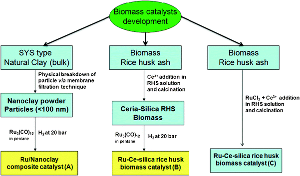 |
| | Scheme 1 Synthetic pathway for low cost green catalyst development from natural available clay and rice husk biomass materials. | |
2. Experimental section
2.1 Materials
Clay nanoparticles (Fe–Mg enriched smectite) was isolated from naturally available black soil of eastern Taiwan. The detailed methodology for soil treatment and the clay nanoparticle isolation process are reported elsewhere.13 Preparation of clay nanoparticles (<100 nm) from Fe–Mg-smectite via an automated ultrafiltration device is shown in Scheme 2. The rice husk (RH) was obtained from a rice mill in Penang, Malaysia. The white rice husk ash (RHA) obtained was used for the preparation of the supported catalysts. Ru3(CO)12, cerium nitrate and RuCl3 was purchased from Sigma-Aldrich Inc., and used without further purification. A stainless steel autoclave with an inserted glass tube and temperature controlled magnetic stirrer setup was used for catalytic hydrogenation process.
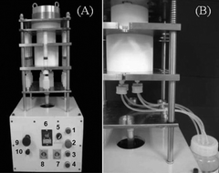 |
| | Scheme 2 Photograph showing the automated ultrafiltration device (AUD) apparatus (A) and one large Teflon container covered (diameter 12 cm, length 9 cm, volume 1018 mL) in central part. | |
2.2 Ru/Nanoclay-A preparation from Ru organometallic precursor
The isolated nanoclay was obtained by centrifuge processing as well as by an automated ultrafiltration device (AUD).14 The natural clay suspension (<2000 nm size fraction) was centrifuged at 980 × g (3370 rpm) for 6 min by ultracentrifugation at 4 °C using a Hitachi CR21 refrigerated centrifuge. The settled particles were resuspended in DDW (double distilled water) and sonicated at 170 W and 60 kHz for 1 min by NEY 300 Ultrasonic. The dispersed suspension was then repeatedly centrifuged and washed several times by centrifugation and dispersion method to obtain the 450–2000 nm size fraction. The suspension (<450 nm size fraction) collected from the above mentioned centrifugation process was further separated by AUD using a 100 nm size membrane filter to get the clay particles fraction with a size range of <100 nm. The obtained solution was freeze-dried to get the nanoclay (white flaky solid). The required amount of Ru3(CO)12 (3 mol% of Ru) was added together with the nanoclay powder in pentane solution. Then the solution was poured into a glass tube in a stainless steel autoclave for hydrogenation at 20 bar pressure for 3 h at 323 K. A yellowish solid powder was obtained after the hydrogenation process. This solid was dried and used for the catalysis study. The prepared sample is designated as Ru/Nanoclay-A.
2.3 Ru/Ce-RHS-B biomass catalyst preparation from Ru organometallic precursor
The rice husk (RH) was obtained from a rice mill in Penang, Malaysia. The washed RH was dried at room temperature for 24 h. About 30.0 g of clean RH was stirred in 750 mL of 1.0 M HNO3 at room temperature for 24 h to remove metallic impurities. The acid-treated RH was washed with distilled water until the pH of the rinse was constant. The RH was dried and burned in a muffle furnace at 873 K for 6 h for complete combustion to form rice husk ash (RHA). About 3.0 g of RHA was stirred to dissolve completely in 1.0 M NaOH (300 mL) to obtain sodium silicate solution. Cetyltrimethylammonium bromide (CTAB, 98%) was added as the structure-directing agent (SiO2![[thin space (1/6-em)]](https://www.rsc.org/images/entities/char_2009.gif) :
:![[thin space (1/6-em)]](https://www.rsc.org/images/entities/char_2009.gif) CTAB = 1
CTAB = 1![[thin space (1/6-em)]](https://www.rsc.org/images/entities/char_2009.gif) :
:![[thin space (1/6-em)]](https://www.rsc.org/images/entities/char_2009.gif) 0.05) and titrated with 3.0 M HNO3 containing cerium nitrate hexahydrate (10 wt% Ce) with constant stirring to pH 3. The gel was aged for 24 h, filtered, washed several times with distilled water followed by acetone and dried. The resulting sample was calcined at 773 K in air to obtain bulk ceria-modified RHS (Ce-RHS). The obtained Ce-RHS was mixed with Ru3(CO)12 (3 mol% Ru) in pentane solution and poured into a thick glass tube for hydrogenation at 20 bar pressure for 3 h. The yellowish solid powder obtained after the hydrogenation process was dried for further analysis. The as-prepared sample is designated as Ru/Ce-RHS-B.
0.05) and titrated with 3.0 M HNO3 containing cerium nitrate hexahydrate (10 wt% Ce) with constant stirring to pH 3. The gel was aged for 24 h, filtered, washed several times with distilled water followed by acetone and dried. The resulting sample was calcined at 773 K in air to obtain bulk ceria-modified RHS (Ce-RHS). The obtained Ce-RHS was mixed with Ru3(CO)12 (3 mol% Ru) in pentane solution and poured into a thick glass tube for hydrogenation at 20 bar pressure for 3 h. The yellowish solid powder obtained after the hydrogenation process was dried for further analysis. The as-prepared sample is designated as Ru/Ce-RHS-B.
2.4
In situ Ru-Ce/RHS-C preparation via RuCl3 precursor method
About 3.0 g of RHA was stirred to dissolve completely in 1.0 M NaOH (300 mL) to obtain sodium silicate solution. The prepared solution was titrated together with CTAB and 3.0 M HNO3 containing dissolved metal salts in the required quantity [RuCl3 (5 wt% Ru) and Ce(NO3)3·6H2O (10 wt% Ce)] at constant stirring and the pH maintained around 3. The gel was aged for 24 h, filtered, washed several times with distilled water followed by acetone and dried in an oven at 373 K for 24 h. The samples were calcined at 773 K in a muffle furnace in air. The prepared sample is designated as Ru-Ce/RHS-C.
2.5 Catalyst test reaction
The stainless steel autoclave with an inserted glass tube was used as a pressurized vessel to study the catalytic activity. The catalytic benzene hydrogenation under hydrogen pressure was studied between 20–60 bar (2.0–6.0 MPa, 1MPa = 10 bar) and temperature was varied between 313–333 K (40–60 °C, 0 °C = 273 K). The liquid phase hydrogenation of benzene was carried out in a 50 mL stainless steel autoclave with a mechanical stirrer. After the desired amount of ZnSO4 was dissolved in 100 mL distilled water, 0.2 g of the prepared catalyst and 5 mL benzene were poured into reactor vessel. Then the autoclave was sealed and purged with H2 at least three to four times to expel air before being fixed at a constant pressure. The catalytic reaction product was analyzed by Agilent gas chromatography with an SPB capillary column. Benzene conversion and selectivity was calculated in mol% by using the known concentration of authentic samples.
3. Results and discussion
3.1 Catalytic activity of benzene hydrogenation on Ru nanoparticle-deposited Nanoclay and rice husk silk materials
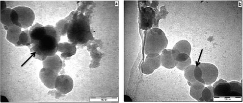
The catalytic conversion and selectivity of synthesized catalysts for catalytic benzene hydrogenation are shown in Table 1 and Fig. 1. The Ru/Ce-RHS-B catalyst shows higher conversion for selective hydrogenation of benzene under high pressure condition among other catalysts. The maximum conversion of 85% and 72% selectivity towards cyclohexene formation was obtained. Ru/Nanoclay-A showed 64% benzene conversion and 40% selectivity for cyclohexene. Ru-Ce/RHS-C showed 78% conversion and 65% selectivity for cyclohexene formation. The effect of variation in hydrogen pressure on catalytic hydrogenation of benzene has been studied such as 10, 20, 30 and 40 bars. The results are shown in Fig. 1A. The maximum conversion for benzene hydrogenation was achieved at 40 bar (4.0 MPa) pressure on Ru/Ce-RHS-B. The bulk Ce-RHS catalyst gave 62% conversion for benzene hydrogenation reaction and less (39%) selectivity towards cyclohexene formation. The superior catalytic conversion obtained by Ru/Ce-RHS-B is due to the fine, aggregated ruthenium nanoparticle dispersion on sphere shape large ceria modified on rice husk silica support. The promoting effect of ceria large particles and ruthenium nanoparticle dispersion enhance the catalytic conversion for benzene hydrogenation. TEM images show aggregated ruthenium nanoparticle deposition on rice husk support with large size ceria dispersion (Fig. 5).
| Catalyst |
Conv.b (mol%) |
Sel.b (%) |
Yieldb (%) |
TOFc (sec−1) |
|
Reaction conditions: catalyst = 0.2 g; 5 mL benzene, 50 mL water, temperature 313 K (40 °C), H2 pressure of 4.0 MPa (40 bar), stirring rate of 1200 rpm, and CZnSO4 = 0.14 M.
Values obtained at maximum yield of cyclohexene.
The catalyst activity was expressed in terms of turnover frequency (TOF, s−1) calculated as the ratio of the concentration of benzene consumed per unit time to the concentration of the total metal dopant.
|
| Ce(10 wt%)-RHS |
62±0.18 |
39 |
42 |
0.3 |
| Ru(3%)/Nanoclay-A |
64±0.58 |
40 |
25 |
0.8 |
| Ru(3%)/Ce(10 wt%)-RHS-B |
85±0.43 |
72 |
45 |
1.2 |
| Ru(5%)-Ce(10 wt%)/RHS-C |
78±0.38 |
65 |
24 |
0.5 |
| Colloidal Ru-stabilized silica12 |
68 |
62 |
42 |
0.8 |
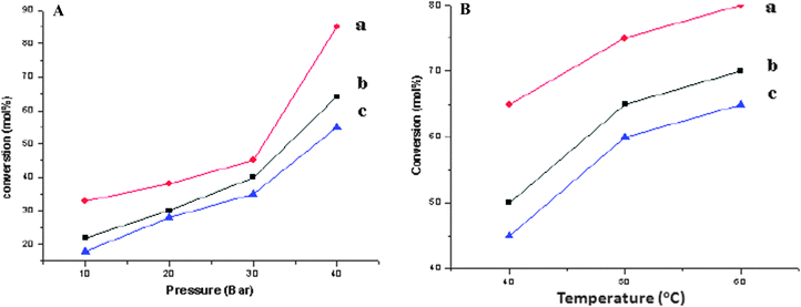 |
| | Fig. 1 A: Selective catalytic hydrogenation on (a) Ru/Ce-RHS-B, (b) Ru-Ce/RHS-C and (c) Ru/Nanoclay-A. Reaction conditions: catalyst = 0.1 g, 2.5 mL benzene, 30 mL water, temperature 313 K (40 °C), H2 pressure of 4.0 MPa (40 bar), stirring rate of 1200 rpm, and CZnSO4 = 0.14 M. B: Selective catalytic hydrogenation on (a) Ru/Ce-RHS-B, (b) Ru-Ce/RHS-C and (c) Ru/Nanoclay-A, at 3.0 MPa (30 bar) with different temperatures. Reaction conditions: catalyst = 0.5 g, 5 mL benzene, 30 mL water, temperature 313 K–333 K (40–60 °C), H2 pressure of 5.0 MPa (50 bar), and CZnSO4 = 0.14 M. | |
The catalytic activities of the above mentioned four catalysts were tested twice under the same reaction conditions to study the recyclability nature of the catalyst and were found to show the same reactivity towards benzene hydrogenation (Table 1). The literature-reported data of colloidal ruthenium particle stabilized silica for catalytic benzene conversion and turn over frequency (TOF) have also been included in Table 1. The microemulsion method was used to stabilize the ruthenium nanoparticles on silica. The microemulsion method is time consuming and less cost effective compared to our method preparing ruthenium nanoparticles on low cost clay and biomass support.
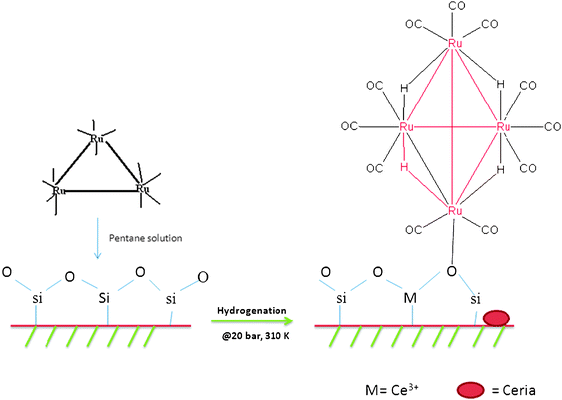
Another factor for the effective conversion achieved by the Ru/Ce-RHS-B catalyst is the ruthenium nanoparticle formation from an organometallic precursor. X-Ray diffraction patterns of Ru/Nanoclay-A and Ru/Ce-RHS-B further support the evidence for higher catalytic activity via the existence of tetranuclear Ru-clusters compared to conventionally prepared catalyst (Ru-Ce/RHS-C). A pictorial representation of a tetranuclear ruthenium cluster formation upon hydrogenation in the presence of a silica support is shown in Scheme 3. Generally, thermal treatment of ruthenium dodecacarbonyl complexes in hydrocarbon solvent transform the complexes into tetranuclear ruthenium clusters.
3.2 Effect of high pressure condition and various temperature conditions for catalytic hydrogenation of benzene
Effects of variation in hydrogen pressure and reaction temperature for catalytic benzene hydrogenation have also been studied and the results are presented in Fig. 1A and B. Higher benzene conversion was observed upon increasing the hydrogen pressure from 1 MPa to 4 MPa (10–40 bar). The Ru/Ce-RHS-B catalyst showed the maximum conversion with respect to different pressure conditions among other catalysts. Ru/Nanoclay-A showed improved conversion compared to Ru-Ce/RHS-C prepared by the conventional route. The effect of an increase in temperature at constant pressure has also been studied on the above mentioned three catalysts. The optimized conversion was observed upon increasing the temperature. The lowest benzene conversion was observed at a low temperature (313 K) and the maximum conversion was observed with an increase in temperature (333 K) with Ru/Ce-RHS-B > Ru-Ce/RHS-C > Ru/Nanoclay-A.
The mechanism for benzene hydrogenation normally proceeds via a planar π-complex of benzene and undergoes a stepwise hydrogenation through linear σ-bonded benzene in the presence of hydride bond formation with different catalytic sites of ruthenium nanoparticle-coated silica support.16 The hydride bond formation with tetranuclear ruthenium nanoparticles on a silica support plays a role in obtaining the maximum conversion for benzene. Hence, tetranuclear ruthenium cluster existence in Ru/Nanoclay-A and Ru/Ce-RHS-B show maximum and effective conversion for benzene to cyclohexene compared to conventionally prepared Ru-Ce/RHS-C and bulk Ce-RHS catalysts. The surface functional groups, physico-chemical characteristics and textural properties of the aforementioned catalysts were studied by various techniques and explained below in detail.
3.3 Surface and structural characterization of Ru/Nanoclay-A, Ru/Ce-RHS-B and Ru-Ce/RHS-C catalysts
The XRD patterns of isolated Fe–Mg enriched smectite-type nanoclay, Ru nanoparticle on nanoclay (Ru/Nanoclay-A), Ru nanoparticle on Ce-RHS (Ru/Ce-RHS-B) and Ru-Ce/RHS-C are shown in Fig. 2. Two intense peaks appeared (2θ = 12–15°) for both Ru/Nanoclay-A and Ru/Ce-RHS-B due to crystalline tetranuclear ruthenium carbonyl cluster formation in presence of nanoclay and RHS support, respectively23 (Fig. 2b and c), whereas only one peak is observed at 12.5° (2θ) in the isolated nanoclay (Fig. 2a). The ruthenium nanoparticle-coated Ru/Ce-RHS-B shows the partial crystalline phase formation together with the amorphous silica surface (Fig. 2c), which was observed between 10–50°. The broad peak observed between 20–30° was due to the amorphous silica.16Fig. 2d shows only a broad X-ray diffraction peak for Ru-Ce/RHS-C and the same kind of XRD pattern is observed in the case of bulk Ce-RHS, due to amorphous nature of the silica derived from RHS.16 Hence, ruthenium nanoparticle deposition on nanoclay and RHS biomass support improves the crystalline nature of the material.
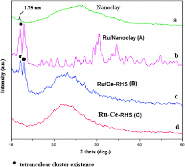 |
| | Fig. 2 XRD patterns of (a) Nanoclay, (b) Ru/Nanoclay-A, (c) Ru/Ce-RHS-B and (d) Ru-Ce/RHS-C. | |
The FT-IR spectra of the samples were recorded in the range 400–4000 cm−1 and are shown in Fig. 3. Fig. 3a and b show the corresponding vibration spectra of Ru/Nanoclay-A and undoped nanoclay. A new vibration frequency appeared at 2066 cm−1 after ruthenium nanoparticle deposition on nanoclay (marked as circle in Fig. 3). Fig. 3c and d show the FT-IR spectra of ruthenium nanoparticle deposition on RHS materials (Ru/Ce-RHS-B and Ru-Ce/RHS-C, respectively). Broad absorption bands at 1640 and 3460 cm−1 correspond to the vibration bands of adsorbed H2O molecules.17 RHS materials show weak absorption bands at 2854 and 2925 cm−1 and stretching vibrations at ∼1479 cm−1.18 The strong bands at 1095, 801 and 467 cm−1 are due to presence of Si–O–Si bond.19 The band at ∼974 cm−1 is due to the presence of Si–OH stretching vibration.20 The change in intensity of the band with increasing cerium content indirectly proves the incorporation of ceria deposition on rice husk silica matrix compared to unmodified RHS (spectrum not shown). Replacement of Si with Ce in the calcination process causes a decrease in intensity of the 974 cm−1 band via changing Si–O–H into Si–O–Ce and the same thing was observed in the case of Ce-MCM-41 synthesis.21a Ru/Nanoclay-A and Ru/Ce-RHS-B materials show new absorbance bands at 2050–2100 cm−1 (marked as circle in Fig. 3a and c) and can be associated to the ruthenium cluster existence.21b The conventionally prepared Ru-Ce/RHS-C shows similar spectrum to Ce-RHS. The co-precipitation ruthenium nanoparticle deposition favors nanoparticle dispersion on silica surface instead of incorporation or altering the functional groups present in RHS.
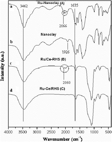 |
| | Fig. 3 FT-IR spectra of (a) Ru/Nanoclay-A, (b) Nanoclay, (c) Ru/Ce-RHS-B (d) Ru-Ce/RHS-C. | |
 |
| | Fig. 4 (a–b) Transmission electron micrographs of Ru/Nanoclay-A. | |
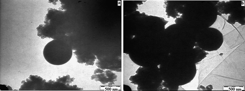 |
| | Fig. 5 (a–b) Transmission electron micrographs of Ru/Ce-RHS-B. | |
SEM micrographs of Ru/Nanoclay-A is shown in Fig. 6a and b. Flaky pastry morphology was observed for the nanoclay support. The ruthenium nanoparticle cluster formation exists in the form of fine hexagonal shapes on the flaky pastry morphology of nanoclay surface. Fig. 6c and d show the SEM micrographs of tetranuclear ruthenium cluster particles on Ce-RHS support (Ru/Ce-RHS-C). The SEM image of Ru/Ce-RHS-B coincides with ruthenium nanoparticle deposition on Al-MCM-41 support.25 Ru/Ce-RHS-B shows the aggregated particle morphology with larger spherical shaped ceria particle deposition on the silica support. The aggregated morphology of the ruthenium clusters did not affect the morphology of the support due to the dispersion of the fine ruthenium nanoparticles.26Fig. 6e and f show SEM micrographs of Ru-Ce/RHS-C and they show an aggregated powdery morphology instead of large particle aggregation on the silica surface.
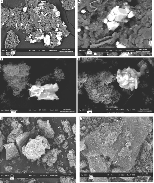 |
| | Fig. 6 (a–b) Scanning electron micrographs of Ru/Nanoclay. (c–d) Scanning electron micrographs of Ru/Ce-RHS-B. (e–f) Scanning electron micrographs of Ru-Ce-RHS-C. | |
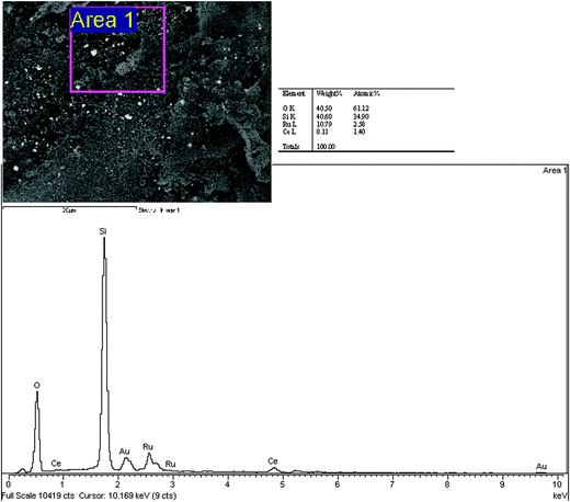
SEM-EDX analysis of Ru/Nanoclay is shown in Fig. 7a. In Fig. 7a, the area around the hexagonal shaped particle dispersed with flaky pastry particles of nanoclay shows the corresponding elemental content at that site and the respective EDX graph is shown together with the SEM image. The existence of Na (4.6%) and Fe (5.1%) in Ru/Nanoclay-A was due to nature of the iron-rich smectite clay and was found to be considerably less than the ruthenium (55.8%) content at the particular site of Fig. 7a. The diamond shaped ruthenium cluster formation possesses the higher ruthenium content. Other parts of Fig. 7a showing the flaky pastry particle contained less ruthenium and a large amount of Na (image not shown), due to sodium present in natural black soil. The presence of carbon at some sites is due to organic carbon present in the natural clay as well as from carbonyl group decomposition from ruthenium carbonyl clusters. The elemental content of the Ru/Ce-RHS-B is shown in Fig. 7b. The aggregated particle morphology of the biomass support is clearly observed in Fig. 8a. Area 1 in Fig. 8a shows ruthenium and cerium content present in limited levels. The higher carbon and silicon content accounts for the siliceous nature of the biomass material and ruthenium cluster formation. Fig. 8b shows the target area of a ruthenium cluster dispersed on aggregated Ce-RHS biomass material. The elemental content value is shown in the table opposite. This second site of Ru/Ce-RHS-B (large white color particle in Fig. 6d) has also been analyzed by EDX, the elemental content of that particular site accounts for the higher amount of ruthenium compared to carbon and oxygen. The spherical whitish ruthenium cluster with a size range of around 5–8 μm was dispersed on the Ce-RHS support. The SEM-EDX spectrum and elemental content of Ru-Ce-RHS-C is shown in Fig. 7c and 9. The EDX spectrum of marked area in Fig. 9 is recorded and it clearly accounts for the existence of ruthenium (10.79%), cerium (8.11%), oxygen (40.50%) and silicon (40.50%) content.
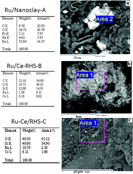 |
| | Fig. 7 SEM-EDX of (a) Ru/Nanoclay-A, (b) Ru/Ce-RHS-B, (c) Ru-Ce/RHS-C. | |
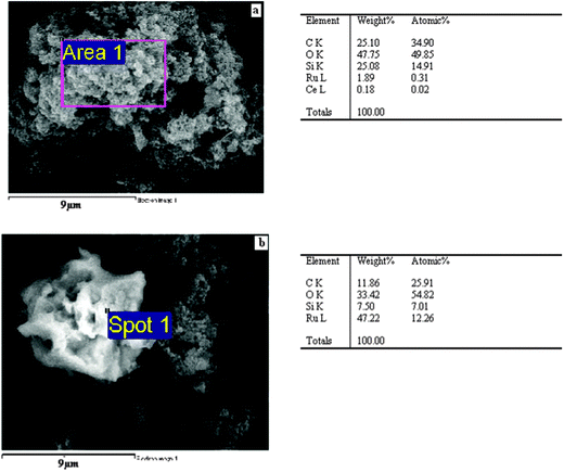 |
| | Fig. 8 (a) and (b) SEM-EDX of Ru/Ce-RHS-B. | |
4. Conclusions
Low-cost green catalysts were derived from naturally available low-cost clay and biomass materials by adopting novel synthetic strategies. An Ru-organometallic precursor was used as the starting material to make ruthenium nanoparticle-coated green catalysts. The as-prepared catalysts, Ru/Nanoclay-A and Ru/Ce-RHS-B, were shown to facilitate effective benzene hydrogenation compared to the conventionally prepared Ru-Ce/RHS-C catalyst. Nanoclay (clay particles size <100 nm) isolated from Fe and Mg enriched smectite clay material and rice husk silica derived from rice husk ash were successfully adopted as support materials. Catalytic hydrogenation of benzene to cyclohexene was successfully tested under high pressure conditions. Ru/Ce-RHS-B showed the maximum conversion (85%) for catalytic benzene conversion due to aggregated fine ruthenium nanoparticle dispersion on ceria modified rice husk silica. The selectivity and yield towards cyclohexene formation were 72% and 45%, respectively. Ru-Ce/RHS-C showed slightly less efficiency compared to the Ru/Ce-RHS-B catalyst but improved catalytic activity compared to Ce(10wt%)-RHS. XRD patterns of Ru/Nanoclay-A and Ru/Ce-RHS-B materials clearly evidenced the tetranuclear cluster formation upon hydrogenation process for ruthenium nanoparticle formation on support material. Ru/Nanoclay-A showed a flaky pastry morphology, whereas Ru/Ce-RHS-B showed an aggregated ruthenium nanoparticle morphology with larger spherical shape ceria particle deposition. Elemental analysis confirmed the amount of ruthenium content dispersion on nanoclay and rice husk biomass support materials. Therefore, the above mentioned Ru-nanoparticle based green catalysts derived from naturally available supports could be eco- and environmentally-friendly low-cost catalysts for monoaromatic hydrogenation.
Acknowledgements
The authors thank the Universiti Sains Malaysia (USM) and National Taiwan University (NTU) for financial support and all facilities provided by respective divisions.
References
- A. E. Ahmed and F. Adam, Micropor. Mesopor Mater., 2007, 103, 284 CrossRef CAS.
- S. Dash, S. Mishra, S. Patel and B. K. Mishra, Adv. Colloid Interface Sci., 2008, 140, 77 CrossRef CAS.
- S. Chiarakorn, T. Areerob and N. Grisdanurak, Sci. Technol. Adv. Mater., 2007, 8, 110 CrossRef CAS.
- F. Adam, K. Kandasamy and S. Balakrishnan, J. Colloid Interf. Sci., 2006, 304, 137 CrossRef CAS.
- F. Adam F and I. A. Sugiarmawan, J. Porous Mater., 2009, 16, 321 CrossRef.
- F. Adam and A. E. Ahmed, Chem. Eng. J., 2008, 145, 328 CrossRef CAS.
- Z. Yujun, Z. Jin, Z. Jianguo, L. Deyi and W. Shudong, Ind. Eng. Chem. Res., 2008, 47, 4641 CrossRef.
- A. Salvini, P. Frediani, C. Giannelli and L. Rosi, J. Organomet. Chem., 2005, 690, 371 CrossRef CAS.
- K. Ramalingam, S. T. Lee, M. Parameswary, H. K. Fun and K. Sivakumar, Polyhedron, 1998, 17, 1211 CrossRef.
- G. Beamson, A. J. Papworth, C. Philipps, A. M. Smith and R. Whyman, Adv. Synth. Catal., 2010, 352, 869 CAS.
- J. L. Liu, L. J. Zhu, Y. Pei, J. H. Zhuang, H. Li, H.-X. Li, M.-H. Qiao and K.-N. Fan, Appl. Catal., A, 2009, 353, 282 CrossRef CAS.
- J. Ning, J. Xu, J. Liu and F. Lu, Cataly. Lett., 2006, 109, 3 Search PubMed.
- C. W. Pai, M. K. Wang, W. M. Wang and K. H. Houng, Clays Clay Miner., 1999, 47, 389 CAS.
- T. M. Tsao TM, M. K. Wang and P. M. Huang, Soil Sci. Soc. Am. J., 2009, 73, 1808 CrossRef.
-
(a) H. E. Fekkul, J. M. Berlie, D. J. Stanton and M. Baird, Can. J. Chem., 1983, 61, 1306 CrossRef;
(b) F. Su, L. Lv, F. Y. Lee, T. Liu, A. I. Cooper and X. Z. Zhao, J. Am. Chem. Soc., 2007, 129, 14213 CrossRef CAS.
- K. H. V. Prasad, K. B. S. Prasad, M. M. Mallikarjunan and R. Vaidyeswaran, J. Catal., 1983, 84, 65 CrossRef CAS.
- T. Radhika and S. Sugunan, Catal. Commun., 2006, 7, 528 CrossRef CAS.
- L. Peng, W. Qisui, L. Xi and L. Chaocan, Colloids Surf., A, 2009, 334, 112 CrossRef.
- W. Xue, H. He, J. Zhu and P. T. Yuan, Spectrochim. Acta, Part A, 2007, 67, 1030 CrossRef.
- N. Venkatathri, Solid State Commun., 2007, 143, 493 CrossRef CAS.
-
(a) S. H. Park, B. Y. Song and T. G. Lee, J. Ind. Eng. Chem., 2008, 14, 261 CAS;
(b) D. Cauzzi, C. Graiff, R. Pattacini, G. Predieri and A. Tiripicchio, J. Braz. Chem. Soc., 2003, 14, 908 CrossRef CAS.
- S. C. Laha, P. Mukherjee, S. R. Sainkar and R. Kumar, J. Catal., 2002, 207, 213 CrossRef CAS.
- S. Yamamoto, K. Asakura, K. Mochida, A. Nitta and H. Kuroda, J. Phys. Chem., 1993, 97, 656 CrossRef CAS.
- A. Indra, S. Basu, S. D. Kulkarni, C. S. Gopinath, S. Bhaduri and G. K. Lahiri, Appl. Catal., A, 2008, 344, 124 CrossRef CAS.
- M. Lakshmi Kantam, B. Purna Chandra Rao, B. M. Choudary and B. Sreedhar, Adv. Synth. Catal., 2010, 348, 1970 CrossRef.
- C. M. G. Judkins, A. Kevin, K. A. Knights, B. F. G. Johnson, R. Yolanda de Miguel, R. Raja and J. Meurig Thomas, Chem. Commun., 2001, 2624 RSC.
|
| This journal is © The Royal Society of Chemistry 2012 |
Click here to see how this site uses Cookies. View our privacy policy here. 

![[thin space (1/6-em)]](https://www.rsc.org/images/entities/char_2009.gif) :
:![[thin space (1/6-em)]](https://www.rsc.org/images/entities/char_2009.gif) CTAB = 1
CTAB = 1![[thin space (1/6-em)]](https://www.rsc.org/images/entities/char_2009.gif) :
:![[thin space (1/6-em)]](https://www.rsc.org/images/entities/char_2009.gif) 0.05) and titrated with 3.0 M HNO3 containing cerium nitrate hexahydrate (10 wt% Ce) with constant stirring to pH 3. The gel was aged for 24 h, filtered, washed several times with distilled water followed by acetone and dried. The resulting sample was calcined at 773 K in air to obtain bulk ceria-modified RHS (Ce-RHS). The obtained Ce-RHS was mixed with Ru3(CO)12 (3 mol% Ru) in pentane solution and poured into a thick glass tube for hydrogenation at 20 bar pressure for 3 h. The yellowish solid powder obtained after the hydrogenation process was dried for further analysis. The as-prepared sample is designated as Ru/Ce-RHS-B.
0.05) and titrated with 3.0 M HNO3 containing cerium nitrate hexahydrate (10 wt% Ce) with constant stirring to pH 3. The gel was aged for 24 h, filtered, washed several times with distilled water followed by acetone and dried. The resulting sample was calcined at 773 K in air to obtain bulk ceria-modified RHS (Ce-RHS). The obtained Ce-RHS was mixed with Ru3(CO)12 (3 mol% Ru) in pentane solution and poured into a thick glass tube for hydrogenation at 20 bar pressure for 3 h. The yellowish solid powder obtained after the hydrogenation process was dried for further analysis. The as-prepared sample is designated as Ru/Ce-RHS-B.

