Structures of medium sized tin cluster anions†
Received
9th September 2011
, Accepted 11th October 2011
First published on 9th November 2011
Abstract
The structures of medium sized tin cluster anions Snn− (n = 16–29) were determined by a combination of density functional theory, trapped ion electron diffraction and collision induced dissociation (CID). Mostly prolate structures were found with a structural motif based on only three repeatedly appearing subunit clusters, the Sn7 pentagonal bipyramid, the Sn9 tricapped trigonal prism and the Sn10 bicapped tetragonal antiprism. Sn16− and Sn17− are composed of two face connected subunits. In Sn18−–Sn20− the subunits form cluster dimers. For Sn21−–Sn23− additional tin atoms are inserted between the building blocks. Sn24− and Sn25− are composed of a Sn9 or Sn10 connected to a Sn15 subunit, which closely resembles the ground state of Sn15−. Finally, in the larger clusters Sn26−–Sn29− additional bridging atoms again connect the building blocks. The CID experiments reveal fission as the main fragmentation channel for all investigated cluster sizes. This rather unexpected “pearl-chain” cluster growth mode is rationalized by the extraordinary stability of the building blocks.
1. Introduction
Bulk tin shows a large variation in physical properties reflecting different structures and bonding characteristics. Under ambient conditions, the thermodynamically most stable phase is the metallic β-tin which has a body centered tetragonal lattice. Slightly below room temperature (286 K) the covalently bonded α-tin with a cubic diamond structure is the most stable allotrope. In contrast to the well-established properties of the lighter element clusters of group 14, still not much is known about the properties of tin clusters, especially their structures. However, structure is a very important characteristic for understanding the physical and chemical properties of the cluster. For example, the question still arises whether tin clusters show more metal-like or more semiconductor-like properties, since in the bulk both types of corresponding crystal structures exist.
Fragmentation experiments carried out for isolated Snn+ have shown fragmentation behaviour which strongly resembles that of Gen+: monomer evaporation was the main decay channel for clusters with up to 11 atoms, whereas for clusters with ≥12 atoms mainly fission occurred.1–3 Similar fragmentation behavior was detected for Sin+, however for these clusters fission already dominates for sizes with n ≥ 9.4Tin clusters (as well as gallium clusters) show extraordinary behavior concerning their “melting points”, which were shown to be higher than for the bulk at the investigated cluster sizes. This has been inferred from both experimental (on cations)5–8 and theoretical studies9–11 and suggests that the structures of these clusters may have non-metal like features. Ion mobilities of tin cluster cations have been measured for clusters with up to 68 atoms. Globally, a development from quasispherical to prolate structures was observed within the size range of up to ∼35 atoms. This is followed by a decrease of the prolate character (and return to more spherical structures) for larger sizes.7 In general the evolution of the shape of tin clusters was found to be more similar to silicon and germanium than to lead clusters.7,12,13 Ion mobility studies on tin cluster cations (generated using laser vaporization) have been carried out at a variety of drift cell temperatures. Whereas at room temperature only one isomer was resolved at each size, at liquid nitrogen temperatures roughly a quarter of the clusters in the n ≥ 18 range (n = 18, 21, 24, 27, 37, 44, 46–49) were found to have two isomers, and Sn30+ was in fact found to have three resolvable isomeric forms of roughly equal abundance.
Going beyond global shape, molecular structures of small tin cluster anions have been deduced from density functional theory (DFT) calculations14 by comparison of calculated electronic densities of states and photoelectron spectra by Ganteför et al.15 Since then, photoelectron spectra of Snn− with extended cluster size range and improved resolution have been published16–18 but without structural assignments. As an exception a hollow icosahedral structure (“Stannaspherene”) was found for Sn122− using photoelectron spectroscopy and the same, slightly Jahn–Teller distorted structure for Sn12−.19
Recently, we have investigated the structures of tin cluster cations20 and anions21 with up to 15 atoms using a combined approach of ion mobility spectrometry, trapped ion electron diffraction (TIED) and DFT calculations. For the cluster anions we observed quasispherical structures up to 12 atoms and confirmed the hollow near-icosahedral structure for Sn12−. For Sn13−–Sn15− we found prolate structures composed of face-sharing subunit clusters. Collision induced dissociation (CID) experiments showed that predominantly monomer evaporation is favoured for the small tin cluster anions; the transition to fission-type fragmentation occurs at 8–11 atoms.
In the medium cluster size range only few structure searches have been conducted as yet. Majumder et al. performed DFT calculations on neutral and cationic tin clusters with up to 20 atoms.22,23 Schäfer et al. combined DFT calculations of neutral Snn (n = 6–20) with electric deflection experiments.24
In recent work of our group, the cluster structures of some chosen sizes of Snn− (n = 18–25) have been investigated.25 This uncovered a surprising “pearl-chain” cluster-of-clusters growth pattern not yet seen in experiment. In the present work this investigation has been extended to cover a larger size range thus adding structural information on some hitherto uninvestigated sizes. As before we use a combination of TIED experiments and DFT calculations applying a genetic algorithm approach for global minimum structure search. In addition, collision induced dissociation experiments were applied to reveal the thermodynamically most stable fragments of Sn16−–Sn26−.
2. Methods
Details of the trapped ion electron diffraction experiment and the data analysis have been described elsewhere,26–28 here only a brief overview will be given. 105–106tin cluster anions generated in a magnetron sputter source29 are stored in a radio frequency quadrupole ion trap, mass-selected to a single cluster size and thermalized through collisions with He buffer gas to a temperature of 100 ± 2 K. The ion cloud is irradiated by an electron beam (40 keV, ca. 1–2 μA) from a long focal length electron gun. Diffracted electrons from the clusters are detected by a phosphor screen assembly and integrated on an external CCD camera. A reference picture is accumulated by repeating the sequence without cluster ions in the trap. Roughly 500 pictures are taken leading to a total measurement time of 14–16 hours. The summed and reference corrected diffraction pictures are centered and radially integrated, yielding the total experimental scattering intensity, Itot, as a function of the electron momentum transfer, s = 4π/λ sin(θ/2). Considering the atomic scattering intensity, Iat, and an additional unspecific flat background, Iback, the experimental modified molecular scattering function is calculated as sMexpt = s[Itot/(IbackIat) − 1]. The theoretical modified molecular scattering function is approximated by
where s′ = kss, N is the number of atoms in the cluster, Sc and ks are scaling factors, and rij is the distance between two atoms in the cluster. L2 is the harmonic mean squared vibrational amplitude averaged over all distances in the cluster and accounts for thermal vibrations. The comparison of the experimental and the theoretical data is done using a χ2-fit minimizing the differences by varying Sc, L, ks and parameters of the background function Iback. The agreement between experimental scattering function and simulated scattering function of the model structure is quantified by a weighted profile factor
where the weighting factors wi are calculated from the (error-propagated) standard deviation of the experimental data. Note that because of this dependence, comparisons of different Rw values (obtained for different trial structures) are only meaningful within a single experimental dataset.
Our experimental setup to determine collision cross sections has been described in an earlier publication.30 We use a modified Smalley-type laser vaporization source31–33 with a rotating target (0.5 mm thick, 50 mm diameter tin foil, Chempur) and a pulsed valve (General Valve Corp.) to provide the cooling gas (helium, 5 bar backing pressure) and the second harmonic (532 nm) of a Nd-YAG laser (Continuum-ND61) for vaporization. The laser is focused through the expansion nozzle (1 mm throat diameter) onto the target. Both target and cooling gas are held at room temperature. The clusters formed in the expansion enter the acceleration region of a linear time-of-flight mass spectrometer (4.5 kV acceleration voltage) and cluster ions are extracted by applying a pulsed electric extraction field. The resulting cluster mass spectrum is monitored using an auxiliary detector, which can be positioned into the ion beam prior to the drift cell. A pulsed mass gate removes all unwanted cluster ion sizes. The so obtained mass selected ion beam is then decelerated (for CID measurements typically to kinetic energies of 300 eV, lab frame) and injected through a 0.5 mm aperture into a 12 cm long drift cell, filled with 5–6 mbar helium at room temperature. Upon injection the ions undergo multiple collisions with helium atoms resulting in extensive fragmentation. The fragment (and surviving parent) ions are guided by a weak electric field (30 V cm−1) through the drift cell. After being focused by an electrodynamic ion funnel34 the ion cloud leaves the cell through another 0.5 mm aperture. The fragment ion distribution is analyzed by a quadrupole mass filter (Extrel C50, up to 4000 amu) which is scanned synchronously with the vaporization laser and the fragment ion intensities are monitored by a channeltron detector multichannel scaler (EG&G, Turbo-MCS) setup.
C. Molecular electronic structure calculations
Quantum chemical calculations have been carried out to determine candidate structures of tin cluster anions to be compared with experiment. We employed the same procedures that proved useful in previous treatments of tin cluster anions and cations.20,21,25 For this reason only a brief description will be given here. The DFT calculations used the TPSS (Tao, Perdew, Staroverov, Scuseria) functional35 in combination with small-core effective core potentials (ECPs) which include scalar relativistic effects.36 On the technical side we employed the RI-J approximation to treat the electronic Coulomb term37,38 and redundant internal coordinates39 to optimize structures. Analytical second derivatives were computed to ascertain the character of stationary points obtained from the geometry optimization and to make sure that local minima have been located.40,41
A genetic algorithm (GA) was used to obtain a set of low-energy structures.42 For this purpose we used a triple zeta polarization basis, denoted def-TZVP,24 in combination with relatively large-core ECP, which leaves only the 5s and 5p electrons to be treated explicitly.36 Because of the presence of recurring building blocks, we employed a seeding strategy in the GA: for a given cluster size previously optimized structures of smaller species containing these fragments were taken as seed structures, with randomly placed additional atoms. We employed a population size of 40, the number of children varied from 12 for the smaller clusters (n = 16, 18) to 30 for the larger ones. In the best case (Sn25−) convergence was reached in 15 generations—that is no new low-energy structures had been found within the last 10 generations. For Sn17− and the larger clusters the GA was stopped after at most 95 generations since no new low-energy structures had been found in the preceding 20–30 generations.
For the populations so obtained we carried out final structure optimization with small core ECP which leaves the 4s, 4p, 4d, 5s, 5p electrons in the valence space, and a basis set of size (10s9p8d2f)/[6s5p3d2f], denoted def2-TZVP, which gives results close to the basis set limit.43
From previous experience, where DFT/TPSS treatments were compared to coupled cluster calculations,44 we can give a rough estimate of the error to be expected for the final optimization. For clusters relatively similar in structural features one may expect errors around or smaller than 0.1 eV for energy differences of isomers. Larger errors (∼0.2 eV) may occur in some cases: for the two isomers of Sn13+ showing an icosahedral cage and an additional atom inside or outside the shell we obtained an energy difference of 0.29 eV, whereas experiment indicates them to be within 0.1 eV.20 All calculations were carried out with TURBOMOLE v6.2.45XYZ coordinates of all structures presented in this work are given in the ESI.†
3. Structures
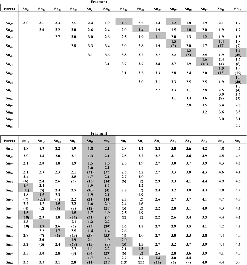
In the following we contrast DFT results and TIED data for every cluster in the size range considered in this work. The structures of the Sn-cluster anions presented here can all be described by assembling just a few different building blocks to a prolate structure. These building blocks are the seven atom pentagonal bipyramid (pb), the nine atom tricapped trigonal prism (ttp) and the ten atom bicapped tetragonal antiprism (bta) (see Fig. 1). The color code labeling the different building blocks is preserved throughout the paper. The structures discussed are usually the four isomers with lowest computed energies, higher-lying geometries are only considered in cases where the best fitting structure is not among the lowest energy isomers.
 |
| | Fig. 1
Snn−
cluster building blocks. (A) Pentagonal bipyramid, (B) tricapped trigonal prism, and (C) bicapped tetragonal antiprism. | |
A.
Sn16−
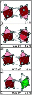
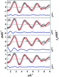
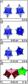
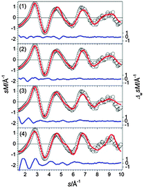
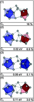
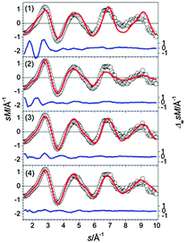
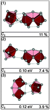
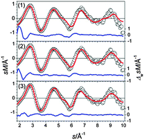
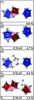
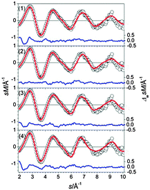
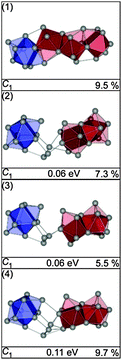
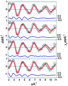
The four lowest energy structures found for Sn16− are shown in Fig. 2. Isomer (1) is a prolate structure composed of a nine atom ttp connected to a seven atom pb. Virtually iso-energetic is structure (2)—two btas sharing a common face in a way that a C2h symmetry results. Isomers (3) and (4) are 0.03 and 0.07 eV above the GM (computed global minimum), isomer (1). They differ from the first two only by the relative orientation of their building blocks. The structure in best agreement with the TIED data (see Fig. 3) is the C2h-structure, isomer (2) (Rw = 3.3%). The Rw-values of all other structures are significantly higher and can be ruled out as significant contributors to the ensemble probed.
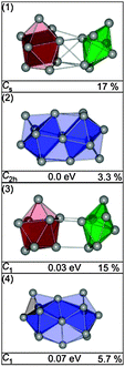 |
| | Fig. 2 Lowest energy structures of Sn16− together with symmetry group, relative energy and profile factor Rw. | |
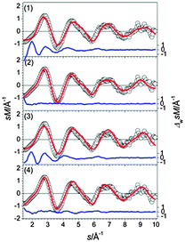 |
| | Fig. 3 Comparison of modified experimental (open circles) and theoretical (red line) molecular scattering functions sM of the lowest energy isomers for Sn16−. The blue lines below are error weighted residuals. | |
B.
Sn17−
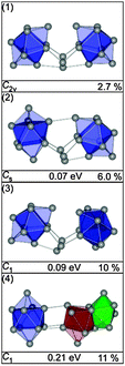
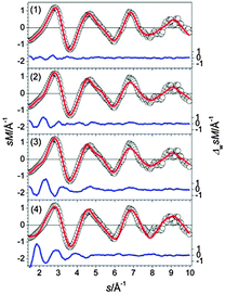
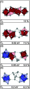
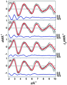
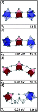
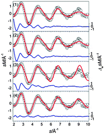
The GM of Sn17− is a bta face-connected to a ttp plus an additional capping atom on the free trigonal face of the ttp (see Fig. 4-1). Virtually iso-energetic (0.01 eV) is a hetero-dimer of a bta and a pb (2) (Fig. 4-2). Isomer (3) is 0.08 eV above the GM and comprises a ttp connected to a pb with an additional capping atom (Fig. 4-3). The structure fitting the TIED data best is isomer (1) (Rw = 5.1%). However, a contribution of isomer (2) in a mixture fit leads to a significant improvement of agreement; Rw drops to 2.0% for a 70/30 mixture (see Fig. 5). A similar result is obtained if isomers (1) and (3) are mixed (ratio 80/20, Rw = 2.2%). Consequently, the ensemble probed has very probably a multi component character. However, in any case the tentative ground state (1) constitutes the major component.
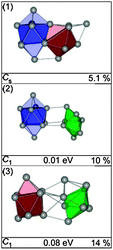 |
| | Fig. 4 Lowest energy structures of Sn17− together with symmetry group, relative energy and profile factor Rw. | |
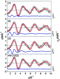 |
| | Fig. 5 Comparison of modified experimental (open circles) and theoretical (red line) molecular scattering functions sM of the lowest energy isomers (1–3) for Sn17−. In the last panel an optimal mixture fit of isomers (1) and (2) in a ratio of 70/30 is shown. The blue lines in the lower parts show the error weighted residuals. | |
C.
Sn18−
The GM of Sn18− comprises two separated ttp units (Fig. 6-1) as described previously.25 The next higher structures in energy (2) and (3) show the same structural motif, only the relative orientations of the ttps differ (Fig. 6-2 and 3). The first isomer showing a different motif is structure (4), a ttp connected to a pb capped by two adatoms (Fig. 6-4). The best agreement with TIED as shown in Fig. 7 is found for the GM. Even though structures (1), (2) and (3) belong to the same structural motif, the TIED experiment is able to discriminate between these structures on the basis of their different Rw values. We rule out structure (4) because of its high relative energy (0.39 eV).
 |
| | Fig. 6 Lowest energy structures of Sn18− together with symmetry group, relative energy and profile factor Rw. | |
 |
| | Fig. 7 Comparison of modified experimental (open circles) and theoretical (red line) molecular scattering functions sM of the lowest energy isomers (1–4) for Sn18−. The blue lines in the lower parts show the error weighted residuals. | |
D.
Sn19−
The GM for Sn19− is a C2v structure composed of two ttps separated by a connecting atom (Fig. 8-1). The next higher isomer (0.12 eV) has a similar motif, two connected ttps with an additional capping atom on a trigonal face of one of the ttp's. Isomer (3), 0.17 eV above the GM, comprises a bta and a ttp. A high profile factor (Rw = 10%) is obtained for the GM (1), while for isomers (2) and (3) profile factors of 5.0% and 6.6% are found (Fig. 8-2 and 3). The best agreement with experiment (Rw = 2.8%) is obtained for a mixture of isomers (2) and (3) with a ratio of 70/30 (see Fig. 9).
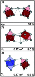 |
| | Fig. 8 Lowest energy structures of Sn19− together with symmetry group, relative energy and profile factor Rw. | |
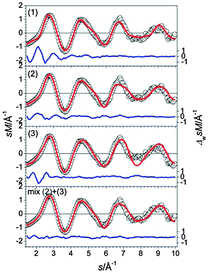 |
| | Fig. 9 Comparison of modified experimental (open circles) and theoretical (red line) molecular scattering functions sM of the lowest energy isomers (1–3) for Sn19−. In the lower panel the corresponding molecular scattering functions of an optimal mixture of isomers (2) and (3) at a ratio of 70/30 is shown. The blue lines in the lower parts show the error weighted residuals. | |
E.
Sn20−
The low-energy structures found for Sn20− are comprised of two bta units in different relative orientations (see Fig. 10) representing again the cluster dimer motif.25 Other structural motifs are high in energy (e.g. isomer (4)). The isomer with the lowest profile factor is the GM (1), however mixtures of isomers of the dimer motif cannot be ruled out (Fig. 11).
 |
| | Fig. 10 Selected low energy structures of Sn20− together with symmetry group, relative energy and profile factor Rw. | |
 |
| | Fig. 11 Comparison of modified experimental (open circles) and theoretical (red line) molecular scattering functions sM of the structures (1–4) for Sn20−. The blue lines in the lower parts show the error weighted residuals. | |
F.
Sn21−
For Sn21− 12 different structures were found within an energy range of 0.1 eV of the GM (1). All of these isomers belong to the same structure motif, a Sn10 bta and Sn9 ttp unit connected by a tin dimer. They differ only by the relative arrangements of the three constituents. In Fig. 12 three isomers of this structure family are shown, the GM (1), the next higher-lying structure (2), virtually-isoenergetic with (1), and the isomer fitting the TIED data the best (3). The first structure having a structural motif different from the isomers above is isomer (4), 0.17 eV above the GM, it comprises two bta units connected by a single atom.
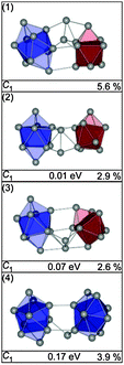 |
| | Fig. 12 Selected structures of Sn21− together with symmetry group, relative energy and profile factor Rw. | |
The experimental data support an assignment as suggested by theory regarding the prevailing structural motif. However, the simulated scattering function of structure (1) shows significant deviation from experimental data (see Fig. 13) and consequently a high profile factor (Rw = 5.6%). The best fitting structures are isomers (2) and (3) (Rw = 2.9 and 2.6%). The calculated energy differences of a few 0.01 eV suggest that a mixture of different isomers is present at the experimental temperature of 100 K. However, no significant improvement in the profile factor is obtained in mixture fits. This does not necessarily imply that no isomer mixtures were present in the ensemble probed, as TIED is only able to differentiate isomers if their scattering functions are sufficiently different. This is not the case for isomers (2) and (3).
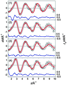 |
| | Fig. 13 Comparison of modified experimental (open circles) and theoretical (red line) molecular scattering functions sM of the structures (1–4) for Sn21−. The blue lines in the lower parts show the error weighted residuals. | |
G.
Sn22−
The structures found for Sn22− up to 0.11 eV belong to two different structural types. The first class [Fig. 14, structures (1), (2) and (4)] shows a Sn10 bta and a Sn9 ttp unit connected by a Sn trimer; the second class comprises two bta units connected by a Sn-dimer [(Fig. 14, structure (3)]. The two structures lowest in energy do not fit the TIED data, as expressed by high profile factors (see also Fig. 15). The best agreement with experiment is found for isomer (4), which belongs to the same structure family but is 0.11 eV higher in energy. Small contributions from the second structure family cannot be ruled out; mixture fits of isomer (4) with other isomers do not improve the profile factor, however.
 |
| | Fig. 14 Selected structures of Sn22− together with symmetry group, relative energy and profile factor Rw. | |
 |
| | Fig. 15 Comparison of modified experimental (open circles) and theoretical (red line) molecular scattering functions sM of the structures (1–4) for Sn22−. The blue lines in the lower parts show the error weighted residuals. | |
H.
Sn23−
The three lowest energy isomers of Sn23− (Fig. 16) are composed of two btas connected by a Sn-trimer.25 The trimer is oriented in such a way that together with the neighboring atoms a distorted cutoff of the diamond lattice results. The GM (1) is also the best fitting structure (Fig. 17). Structures (2) and (3) differ only in the relative orientation of two bta and the bridging atoms but show significantly higher profile factors. Mixtures of (2) or (3) with the GM do not considerably improve the Rw. Similarly, isomers based on a different motif, such as (4), show large Rw-values and can therefore be ruled out.
 |
| | Fig. 16 Lowest energy structures of Sn23− together with symmetry group, relative energy and profile factor Rw. | |
 |
| | Fig. 17 Comparison of modified experimental (open circles) and theoretical (red line) molecular scattering functions sM of the structures (1–4) for Sn23−. | |
I.
Sn24−
A set of low energy structures for Sn24− is shown in Fig. 18. They all comprise a ttp connected to a 15 atom sub-cluster which itself is composed of two face connected ttp units. Interestingly, the 15 atom sub-cluster corresponds to the weakly distorted Sn15− ground state described recently.21 Isomers (1–3) differ only in the relative orientation of the ttp and Sn15 unit. The GM (1) and isomer (2) are prolate structures with a head-on connection of both units. The structure fitting the TIED data best is isomer (3), a structure in which the ttp is bonded side-on to Sn15, 0.12 eV above the GM (Fig. 19). In addition to structure (3) as the major component, a contribution of isomer (2) cannot be ruled out: in a mixture with 30% isomer (2) the profile factor is further reduced (Rw = 3.3%).
 |
| | Fig. 18 Selected structures of Sn24− together with symmetry group, relative energy and profile factor Rw. | |
 |
| | Fig. 19 Comparison of modified experimental (open circles) and theoretical (red line) molecular scattering function sM of the structures (1–3) for Sn24−. | |
J.
Sn25−
The low-energy structures for Sn25− all contain a Sn15 subunit connected to a bta.25 Several isomers of this family were found close in energy, in Fig. 20 only the GM (1) and the next higher-lying isomer (2) (0.04 eV) are shown. They differ only by the relative orientation of their components. A Sn15 connected to a ttp unit plus an adatom is found as a second structural motif in higher energy isomers (>0.12 eV). The additional atom either caps the free trigonal face of the ttp [isomer (3)] or bridges both sub-clusters [isomer (4)]. The lowest Rw-values are found for isomers of the 10 + 15 motif, e.g. the profile factors of isomers (1) and (2) are Rw = 1.6% and 1.9%, respectively (see also Fig. 21). They are almost indistinguishable within the error of the experiment, similarly mixtures of these isomers cannot be ruled out. However, structures deviating from this motif show much larger profile factors (isomers (3) and (4)) and consequently can be ruled out as significant contributors to the ensemble probed.
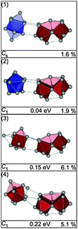 |
| | Fig. 20 Selected structures of Sn25− together with symmetry group, relative energy and profile factor Rw. | |
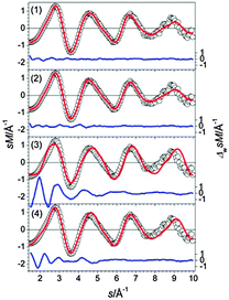 |
| | Fig. 21 Comparison of modified experimental (open circles) and theoretical (red line) molecular scattering functions sM of the structures (1–4) for Sn25−. | |
K.
Sn26−
The lowest energy structures for Sn26− are shown in Fig. 22. The GM (1) is a Sn16 unit composed of a bta face connected to ttp and bound to a second bta and the connectivity may be characterized as 10/9–10. The same motif is found in structure (2) with a different face of the bta connected to the ttp in the Sn16 unit. Isomer (3) is a slight variant of this motif; the Sn atoms connecting the two btas resemble a distorted ttp. Interestingly, the Sn16 subunits in structures (1) and (2) do not correspond to the ground state structure of Sn16−. In structure (4) a different motif is realized, a Sn15 subunit is connected to a ttp by two additional bridging atoms. TIED data favor isomers (2) and (3) (Fig. 23), the best fit is obtained for a mixture (60/40) leading to Rw = 4.0%
 |
| | Fig. 22 Lowest energy isomers of Sn26− together with symmetry group, relative energy and profile factor Rw. | |
 |
| | Fig. 23 Comparison of modified experimental (open circles) and theoretical (red line) molecular scattering functions sM of the structures (1–4) for Sn26−. | |
L.
Sn27−
In our global minimum search we find more than 10 isomers within 0.2 eV of the GM (1). In Fig. 24 we show the three lowest energy structures (1–3). The GM (1) comprises a chain of face connected btas (or alternatively two fused Sn15 units). The TIED data however favor the slightly higher-lying isomers (2) and (3), both composed of a Sn15 unit and a single bta connected by three intermediate Sn-atoms forming a 15–(3)–9 motif (Fig. 25). The first isomer differing from this structural motif is structure (4), 0.2 eV higher in energy, comprised of two ttps plus a set of seven connecting atoms (10–(7)–10). The intermediate atoms cannot be easily assigned to one of the building blocks. Based on the TIED data, only isomer (1) can be ruled out (profile factor of 13%). The best two-component mixture was found for a 40/60 composition of (2) and (3) yielding Rw = 4.4%.
 |
| | Fig. 24 Lowest energy isomers of Sn27− together with symmetry group, relative energy and profile factor Rw. For description of the color code, see Fig. 1. | |
 |
| | Fig. 25 Comparison of modified experimental (open circles) and theoretical (red line) molecular scattering functions sM of the structures (1–4) for Sn27−. | |
M.
Sn28−
The structural motifs found for Sn27− also occur in Sn28−: the GM (1) is a linear chain of fused polyhedra, i.e. a bta and three ttps sharing a common face with the neighboring cluster building blocks (see Fig. 26). The next higher-lying isomers (2–4) are realizations of the 15–(3)–10 motif in different relative orientations of the building blocks. The GM (1) shows a large profile factor and consequently does not significantly contribute to the ensemble probed. The best agreement with the TIED data (see Fig. 27) is found for isomer (3), two component mixtures of isomers (2–4) were considered by virtue of their closeness in energy but do not improve the agreement.
 |
| | Fig. 26 Lowest energy isomers of Sn28− together with symmetry group, relative energy and profile factor Rw. For description of the color code, see Fig. 1. | |
 |
| | Fig. 27 Comparison of modified experimental (open circles) and theoretical (red line) molecular scattering functions sM of the structures (1–4) for Sn28−. The blue lines in the lower parts show the error weighted residuals. | |
N.
Sn29−
The GM found for Sn29− is a chain of two connected btas with a ttp in-between (see Fig. 28, (1)). This motif is found in several low-lying isomers. They differ only by the relative orientations of their constituents (e.g. isomer (2)). Isomer (3), only 0.08 eV higher in energy, is comprised of three ttps connected by two single atoms resulting in a bent global configuration of the cluster. Neither the simulated scattering functions of these structures nor two component mixtures thereof fit the experimental data well. The best agreement with the TIED data is obtained for isomer (4) having a different structural motif: it is composed of a bta, a ttp, and 10 atoms in between in a configurations that cannot be described easily by one of the building blocks Sn7, Sn9 or Sn10. Instead the arrangement of these atoms has some resemblance with a segment of the diamond-like lattice (see also ESI†). Even though this structure is 0.21 eV above the GM, it is the lowest energy structure found for which there is reasonable agreement between TIED data and theory (see Fig. 29).
 |
| | Fig. 28 Selected structures of Sn29− together with symmetry group, relative energy and profile factor Rw. For description of the color code, see Fig. 1. | |
 |
| | Fig. 29 Comparison of modified experimental (open circles) and theoretical (red line) molecular scattering functions sM of the structures (1–4) for Sn29−. The blue lines in the lower parts show the error weighted residuals. | |
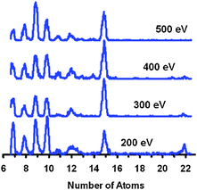 |
| | Fig. 30 Multicollision induced dissociation of Sn22−: fragment ion mass spectra as a function of injection energy (laboratory frame) into the drift cell filled with 5–6 mbar of He. | |
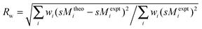
Table 1 Calculated fragmentation energies (in eV) for the channels: Snn− → Snm− + Sn(n–m), 15 < n < 30 and m < 29, and experimentally observed fragment ion intensities (for 15 < n < 27, in parentheses). The calculated fragmentation energies are based on the lowest energy structures for neutral and ionic clusters respectively. Highlighted are the four dominant fragmentation channels, i.e.Sn10− (+Snn–10) and Sn9− (+Snn–9) as well as loss of neutral Sn10 (+Snn–10−) and neutral Sn7 (+Snn–7−)
5. Conclusions and summary
We have assigned structures of medium sized tin cluster anions Snn− (n = 16–29) using a combination of trapped ion electron diffraction and unbiased structure searches using density functional theory. In most cases best agreement with the experimental scattering function is found either for the predicted global minimum or for an energetically close-lying isomer. Only the largest clusters studied here differ regarding predicted and best fitting structural motif (see below). The fragment distributions observed upon collisional dissociation clearly reflect the energetically favored channels. In many cases the observed Snn−cluster structures follow this trend inasmuch as their constituting subunits (Sn7, Sn9 and Sn10) are low in energy and dominate the fragment ion spectra.
Most structures have an elongated prolate shape, similar to what has been predicted for the cations in this size range.7 The only exception is Sn24− where an oblate isomer fits the TIED data best. The common structural motif for clusters in this size range is chains of Sn9 and Sn10 subunits: in Sn16− and Sn17− two fused subunits are found. In Sn18−–Sn23− these subunits separate forming either cluster dimers (Sn18 and Sn20) or two clusters interlinked by additional atoms. For the larger clusters Sn24−–Sn26− we find hetero-dimers consisting of a smaller (Sn9 or Sn10) and a larger (Sn15 or Sn16) subunit, where the latter are themselves composed of two fused Sn9 and/or Sn10 clusters. In the larger cluster Sn27− and Sn28− again additional atoms interlink the two building blocks. It is interesting to note that in these cases DFT predicts global minima with a slightly different structural motif: chains of fused building blocks which could not be confirmed by the TIED experiment. However, the assigned structures are well within the expected error of the DFT calculation of 0.1–0.2 eV. Only for Sn29− do we find a larger deviation of experiment and theory. Here the best fitting structure is not only 0.21 eV above the predicted global minimum; it also differs concerning the predicted structural motif. While the best fitting structure comprises a bta and a ttp with nine interlinking atoms, the GM consists of two bta units connected by a ttp. At present we are not able to identify the source of this discrepancy. Possible explanations are: (i) the correct ground state is not among the structures suggested or (ii) the free energy contributions at the experimental temperature of ∼100 K affect the observed structure.
In closing we note that the ttp and bta based structures presented here cannot be directly related to segments of the tin bulk lattices. Nevertheless, in Sn29− the atomic configuration of the central part of the cluster is similar to a segment of the cubic diamond lattice of α-tin. It is therefore tempting to identify Sn29− as the onset size for the appearance of the bulk structure, however, this needs to be verified by future TIED/DFT investigations of larger tin cluster anions.
Acknowledgements
This research was supported by DFG via the Center for Functional Nanostructures (TP4.6) and by BMBF through the Helmholtz Research Program POF NanoMikro.
References
- Y. Tai, J. Murakami, C. Majumder, V. Kumar, H. Mizuseki and Y. Kawazoe, J. Chem. Phys., 2002, 117, 4317–4322 CrossRef CAS.
- Y. Tai, J. Murakami, C. Majumder, V. Kumar, H. Mizuseki and Y. Kawazoe, Eur. Phys. J. D, 2003, 24, 295–298 CrossRef CAS.
- Y. Tai and J. Murakami, Chem. Phys. Lett., 2001, 339, 9–13 CrossRef CAS.
- M. F. Jarrold and J. E. Bower, J. Phys. Chem., 1988, 92, 5702–5705 CrossRef CAS.
- G. A. Breaux, C. M. Neal, B. Cao and M. F. Jarrold, Phys. Rev. B: Condens. Matter, 2005, 71, 073410 CrossRef.
- A. A. Shvartsburg and M. E. Jarrold, Phys. Rev. Lett., 2000, 85, 2530–2532 CrossRef CAS.
- A. A. Shvartsburg and M. F. Jarrold, Phys. Rev. A, 1999, 60, 1235 CrossRef CAS.
- G. A. Breaux, R. C. Benirschke, T. Sugai, B. S. Kinnear and M. F. Jarrold, Phys. Rev. Lett., 2003, 91, 215508 CrossRef.
- K. Joshi, D. G. Kanhere and S. A. Blundell, Phys. Rev. B: Condens. Matter, 2002, 66, 155329 CrossRef.
- K. Joshi, D. G. Kanhere and S. A. Blundell, Phys. Rev. B: Condens. Matter, 2003, 67, 235413 CrossRef.
- F.-c. Chuang, C. Z. Wang, S. Öğüt, J. R. Chelikowsky and K. M. Ho, Phys. Rev. B: Condens. Matter, 2004, 69, 165408 CrossRef.
- K. M. Ho, A. A. Shvartsburg, B. C. Pan, Z. Y. Lu, C. Z. Wang, J. G. Wacker, J. L. Fye and M. F. Jarrold, Nature, 1998, 392, 582–585 CrossRef CAS.
- A. A. Shvartsburg and M. F. Jarrold, Chem. Phys. Lett., 2000, 317, 615–618 CrossRef CAS.
- B. Wang, L. M. Molina, M. J. López, A. Rubio, J. A. Alonso and M. J. Stott, Ann. Phys., 1998, 7, 107 CrossRef.
- G. Ganteför, M. Gausa, K. H. Meiwes-Broer and H. O. Lutz, Z. Phys. D: At., Mol. Clusters, 1989, 12, 405–409 CrossRef.
- V. D. Moravec, S. A. Klopcic and C. C. Jarrold, J. Chem. Phys., 1999, 110, 5079–5088 CrossRef CAS.
- Y. Negishi, H. Kawamata, A. Nakajima and K. Kaya, J. Electron Spectrosc. Relat. Phenom., 2000, 106, 117–125 CrossRef CAS.
- L.-F. Cui, L.-M. Wang and L.-S. Wang, J. Chem. Phys., 2007, 126, 064505 CrossRef.
- L. F. Cui, X. Huang, L. M. Wang, D. Y. Zubarev, A. I. Boldyrev, J. Li and L. S. Wang, J. Am. Chem. Soc., 2006, 128, 8390–8391 CrossRef CAS.
- N. Drebov, E. Oger, T. Rapps, R. Kelting, D. Schooss, P. Weis, M. M. Kappes and R. Ahlrichs, J. Chem. Phys., 2010, 133, 224302 CrossRef.
- E. Oger, R. Kelting, P. Weis, A. Lechtken, D. Schooss, N. R. M. Crawford, R. Ahlrichs and M. M. Kappes, J. Chem. Phys., 2009, 130, 124305–124310 CrossRef.
- C. Majumder, V. Kumar, H. Mizuseki and Y. Kawazoe, Phys. Rev. B: Condens. Matter, 2001, 64, 233405 CrossRef.
- C. Majumder, V. Kumar, H. Mizuseki and Y. Kawazoe, Phys. Rev. B: Condens. Matter, 2005, 71, 035401 CrossRef.
- A. Schäfer, C. Huber and R. Ahlrichs, J. Chem. Phys., 1994, 100, 5829–5835 CrossRef.
- A. Lechtken, N. Drebov, R. Ahlrichs, M. M. Kappes and D. Schooss, J. Chem. Phys., 2010, 132, 211102 CrossRef.
- D. Schooss, M. N. Blom, J. H. Parks, B. von Issendorff, H. Haberland and M. M. Kappes, Nano Lett., 2005, 5, 1972–1977 CrossRef CAS.
- M. N. Blom, D. Schooss, J. Stairs and M. M. Kappes, J. Chem. Phys., 2006, 124, 244308 CrossRef.
- A. Lechtken, C. Neiss, J. Stairs and D. Schooss, J. Chem. Phys., 2008, 129, 154304 CrossRef.
- H. Haberland, M. Mall, M. Moseler, Y. Qian, T. Reiners and Y. Thurner, J. Vac. Sci. Technol., A, 1994, 12, 2925–2930 CAS.
- P. Weis, S. Gilb, P. Gerhardt and M. M. Kappes, Int. J. Mass Spectrom., 2002, 216, 59–73 CrossRef CAS.
- T. G. Dietz, M. A. Duncan, D. E. Powers and R. E. Smalley, J. Chem. Phys., 1981, 74, 6511–6512 CrossRef CAS.
- W. A. Deheer and P. Milani, Z. Phys. D: At. Mol. Clusters, 1991, 20, 437–439 CrossRef CAS.
- U. Heiz, F. Vanolli, L. Trento and W. D. Schneider, Rev. Sci. Instrum., 1997, 68, 1986–1994 CrossRef CAS.
- A. V. Tolmachev, H. R. Udseth and R. D. Smith, Anal. Chem., 2000, 72, 970–978 CrossRef CAS.
- J. Tao, J. P. Perdew, V. N. Staroverov and G. E. Scuseria, Phys. Rev. Lett., 2003, 91, 146401–146404 CrossRef.
- B. Metz, H. Stoll and M. Dolg, J. Chem. Phys., 2000, 113, 2563–2569 CrossRef CAS.
- K. Eichkorn, O. Treutler, H. Öhm, M. Häser and R. Ahlrichs, Chem. Phys. Lett., 1995, 240, 283–290 CrossRef CAS.
- R. Ahlrichs, Phys. Chem. Chem. Phys., 2004, 6, 5119–5121 RSC.
- M. von Arnim and R. Ahlrichs, J. Chem. Phys., 1999, 111, 9183–9190 CrossRef CAS.
- P. Deglmann, F. Furche and R. Ahlrichs, Chem. Phys. Lett., 2002, 362, 511–518 CrossRef CAS.
- P. Deglmann, K. May, F. Furche and R. Ahlrichs, Chem. Phys. Lett., 2004, 384, 103–107 CrossRef CAS.
- M. Sierka, Prog. Surf. Sci., 2010, 85, 398–434 CrossRef CAS.
- F. Weigend and R. Ahlrichs, Phys. Chem. Chem. Phys., 2005, 7, 3297–3305 RSC.
- N. Drebov and R. Ahlrichs, J. Chem. Phys., 2011, 134, 124308 CrossRef.
- TURBOMOLE V6.2 2010, a development of University of Karlsruhe and Forschungszentrum Karlsruhe GmbH, 1989–2007, TURBOMOLE GmbH, since 2007; available from http://www.turbomole.com.
Footnote |
| † Electronic supplementary information (ESI) available. See DOI: 10.1039/c1cp22874a |
|
| This journal is © the Owner Societies 2012 |
Click here to see how this site uses Cookies. View our privacy policy here.