Probing the structure of long DNA molecules in solution using synchrotron radiation linear dichroism†
Martyn
Rittman
a,
Søren V.
Hoffmann
b,
Emma
Gilroy
c,
Matthew R.
Hicks
c,
Bärbel
Finkenstadt
d and
Alison
Rodger
*c
aZBSA, University of Freiburg, Habsburgerstrasse 49, 79104 Freiburg, Germany
bInstitute for Storage Ring Facilities (ISA), Aarhus University, Ny Munkegade 120, DK-8000 Aarhus C, Denmark
cDepartment of Chemistry and Warwick Centre for Analytical Science, University of Warwick, Coventry, CV4 7AL, UK. E-mail: A.rodger@warwick.ac.uk
dDepartment of Statistics, University of Warwick, Coventry, CV4 7AL, UK
First published on 16th November 2011
Abstract
Linear dichroism (LD), a spectroscopic method for aligned samples, has been used with a synchrotron radiation source to reveal insights into the structure and stability of DNA with increasing salt concentrations (thus stabilizing the base pairing) and increasing temperature while remaining below the melting point (thus destabilizing the base pairing). Measurements have been made from 350 nm to 182 nm, and the spectral changes observed quantified using a Bayesian Markov chain Monte Carlo (MCMC) algorithm, which uses statistical methods to fit to experimental data. Based on literature H–D exchange experiments, we surmise that the cause of the spectral variations is the induction of transient single stranding of tracts in the DNA polymer, particularly those with significant content of the weaker AT base pairs. More detailed analysis of the LD data will require better nucleotide transition polarization assignments.
Introduction
Circular dichroism (CD) spectroscopy is widely used to assess the secondary structure of proteins and the value of synchrotron sources for a wider wavelength range and higher photon flux is apparent in an increasing range of applications.1,2DNA circular dichroism has remained less useful for nucleic acid structure analysis once one has made the crude assignment of polymorph identity (e.g. B, Z, or A-DNA), though it is extremely useful for ligand binding studies.3–5 In this paper we show that the related technique of linear dichroism (LD), which employs linearly polarized light and oriented samples, rather than the circularly polarized light and isotropic samples of most circular dichroism applications, can be used to give structural information about DNA molecules that is not currently available by any other technique. Our focus in this paper is on the effect of salt and temperature on long DNA molecules of different guanine-cytosine (GC) content.LD spectroscopy is a method of absorbance spectroscopy of oriented samples.6,7 It is defined as the difference in absorbance between two perpendicular, linearly polarized beams of light, one of which is usually aligned along the macroscopic orientation axis of the sample. We define reduced LD as6
 | (1) |
LDr = ![[/]](https://www.rsc.org/images/entities/char_e0ee.gif) S(cos2 S(cos2![[thin space (1/6-em)]](https://www.rsc.org/images/entities/char_2009.gif) α − 1) α − 1) | (2) |
α〉). An increase in the quality of LD data has recently been achieved by the use of synchrotron radiation.9
Synchrotron sources produce intense light over a wide range of wavelengths, including in the ultra-violet region. This has two distinct advantages over the sources normally used in bench-top spectrometers (usually a xenon lamp):
(i) The level of noise on the data is greatly reduced, thus data collection is both faster and possible for samples of low intrinsic signals.
(ii) A wider range of wavelengths is available, because a higher sample absorbance at low wavelength may be tolerated and light intensity does not drop off. Most bench-top spectrometers have a practical lower limit between 180 and 190 nm. This can be as high as 220 nm depending on the nature of the sample, its absorbance (often that of the solvent or buffers, which cannot be reduced) and propensity to scatter light. The limitation is due to a low number of high-energy photons entering the detector. In contrast, synchrotron radiation LD is currently limited by the quality of quartz used and no drop-off in signal quality is observed above the quartz cut-off point.
In order to interpret spectroscopic data, various approaches have been adopted. For CD and infrared spectroscopy, curve fitting is often based on the known structures, in particular secondary structures of proteins.10–13 The algorithms then proceed as pattern-recognition based on a set of samples of known structure,14 or calculations of spectra.15 For proteins, much progress has been made in these areas, with good predictions and databases to which one can refer, presumably because of the well-defined structural motifs present in proteins. By way of contrast, little progress has been made for DNA where a continuum of structures is possible. Various approaches, such as those used for mass spectrometry,16 involving data smoothing, base-line subtraction and then a steepest gradient algorithm (or other suitable deterministic fitting methods) have been attempted to extract information from DNA CD. However, it has been noted that smoothing can accentuate (or remove) features within data,11 and we were keen to avoid this whilst still being able to fit comparatively noisy data. With DNA, the approach has in general been to start from the best available (whatever is meant by that) assignments of absorption wavelengths (arising from electron transitions) for each DNA base and endeavour to fit CD and LD spectra from there. Chou and Johnson,17 for example, fitted solution phase data for DNA LD using wavelengths of bands assigned from the literature, log-normal band shapes and a steepest gradient algorithm (Levenberg–Marquardt). They worked with homopolymeric DNA and deduced details of base tilts and propeller twists of base pairs. In addition to relying on accurate literature transition assignments (wavelengths and polarizations18–21), this approach is only viable for synthetic homopolymeric DNA.
We have concluded that the way forward for analysis of DNA LD data (and probably also CD) is to deconvolve spectra into a sum of components and then analyze these in terms of the different component transitions, using the best available transition polarizations. The first stage has been done in this work, namely to establish a Bayesian Markov chain Monte Carlo (MCMC) algorithm that uses statistical methods to provide fits to experimental data that are less sensitive to noise than the existing literature methodologies. This is the first application of such a method to the fitting of LD spectra, and may have wider relevance for spectral fitting. The application of an MCMC algorithm to peak fitting is not widespread, but has been used in several other areas, including identification of a cell signalling pathway, image analysis, medical monitoring and carbon dating.22,23 We deem it to be suitable in this case for several reasons. Firstly, the methodology is now well-established and simple to implement on a desktop computer. Secondly, the fitting is more able to deal with noise than steepest gradient approaches and requires no pre-smoothing. Finally, statistical properties of a Markov chain give a quantitative method for estimating the goodness of fit.
In this paper we present LD data of a number of DNA types being stabilised by the addition of salt and destabilised by heating (while remaining below the melting temperature). We have carried out peak deconvolution of the spectra to determine position, magnitude and width of peaks within each spectrum using MCMC.
Materials and methods
DNA
Seven types of DNAs with different GC (guanosine-cytosine) and AT (adenine-thymine) contents shown in Table 1 were studied. All other chemicals were purchased from Sigma-Aldrich Poole, Dorset, UK.| DNA | GC content (%) | Supplier |
|---|---|---|
| Poly[d(A)]-poly[d(T)] | 0 | Amersham biosciences, Buckinghamshire, UK |
| Poly[(dA-dT)]2 | 0 | Amersham biosciences, Buckinghamshire, UK |
| Single-stranded poly[(dA)] | 0 | Sigma-Aldrich, Dorset, UK |
| Clostridium perfringens DNA | 28.5 | Sigma-Aldrich, Dorset, UK |
| Calf thymus DNA | 42 | Sigma-Aldrich, Dorset, UK |
| Micrococcus luteus DNA | 71.0 | Sigma-Aldrich, Dorset, UK |
| Poly[(dG-dC)]2 | 100 | Sigma-Aldrich, Dorset, UK |
To observe the effect of salt concentration on LD, different amounts of sodium fluoride (NaF) were added. The fluoride salt was used because chloride ions absorb significantly at low wavelengths. The salt, DNA and extra water as-required were mixed to give a sample solution of 200 μM DNA at the requisite ionic strength with the exception of M. luteusDNA, which was used at a concentration of 50 μM. 60 μl of the sample solution were placed in a cell for measurement of an LD spectrum. The DNAs used were of heterogeneous length and there is expected to be a scaling of the LD magnitudes as a function of the length dependence of their orientation parameter, S. In our analysis we focus only on the relative changes in S, thus disregarding the length effect.
Linear dichroism
LD spectra were measured using the UV1 beamline at ASTRID (ISA, Aarhus University, Denmark)24 adapted for LD spectroscopy with a MgF2 Rochon polarizer and a photoelastic modulator. The cell used for experiments was a microvolume Couette flow cell manufactured by either Crystal Precision Optics Couette or Dioptica Scientific Ltd. (available through Kromatek Ltd.).25,26 The rotation motor potential of the cell was 3.0 V (∼3000 rpm), the wavelength range of the spectrometer was 170–350 nm with measurements taken in 1 nm steps with a 1–2.5 s dwell time at each point. A single scan over the wavelength range gave sufficiently small noise for each spectrum. The conversion from mV (the output units from ASTRID) to Δ(absorbance) is 1 mV, which corresponds to ΔA = 3.26 × 10⁻⁴. The sample holder was a quartz capillary with an epoxy resin plug at its base and was cleaned using high purity water and methanol or ethanol between samples. The central rod was extruded quartz.For comparison, some samples were measured using bench-top spectrometers. When a Biologic MOS-450 spectrometer was used the settings were: wavelength range 180–350 nm, rotation motor voltage 3.0 V, bandwidth 4 nm, scan speed 120 nm min−1, number of whole spectrum scans per measurement (accumulations) 3. For a Jasco J-815 spectrometer the following settings were used: wavelength range 180–350 nm, rotation voltage 3.0 V, bandwidth 1 nm, scan speed 100 nm min−1, with 4–8 accumulations depending on the quality of data required.
It was verified (data not shown) that the quality of the quartz in the capillaries of the cell is sufficiently high to render the LD of the capillary the same in all orientations. For each sample, spectra were taken with cell rotation on and off. The latter is a baseline which, when subtracted from the former, gives the LD spectrum.
Curve fitting
The only previous attempt at curve fitting of DNA LD spectra employed a Levenberg–Marquardt algorithm with 4.5 log-normal components per base as discussed above.27 Chou and Johnson used a log-normal function to fit to each spectral peak in the wavelength domain, reasoning that this was suitable due to the asymmetry of peaks. This work established the principle of fitting a distribution function to each spectral peak, which we have followed. However, the algorithm used was not particularly robust and initial parameters had to be carefully chosen to ensure convergence. In addition, the algorithm was frequently stopped early to avoid over-fitting. In this work LD spectra were fitted using an MCMC algorithm28–32 with a frequency domain Gaussian function for each peak. We considered it to be more physical to fit in the energy domain. It should be noted that this introduces some asymmetry when converting back to wavelength after fitting and avoids the need Chou and Johnson found to use an asymmetric function. For fitting of IR data Gaussian, Lorentzian or a mixture of both functions has generally been used. Both of these were tried and we chose Gaussian, as is usually done for electronic spectroscopy. The fitting was treated as a Bayesian inference problem, using an MCMC algorithm which incorporates both Metropolis–Hastings and Gibbs sampling steps. The Metropolis–Hastings algorithm was used to update the model parameters, while the Gibbs step was used to estimate the precision parameter of the likelihood function (see eqn (4)).The approach of MCMC is to construct a Markov chain that eventually samples parameters of a given model, X(m, t), from the posterior distribution28,32P(m|A(t)), given some experimental data, where P denotes probability, m is the model parameters and A(t) is experimental data at points t. By Bayes theorem
| P(m|A) ∝ P(A|m)P(m) | (3) |
The probability P(A|m) can be thought of as a function of m and is thus termed the likelihood function, L(m). P(m) contains any prior information known about the parameters. For the purposes of fitting, the deviations between the data and the curve are assumed to be normally distributed and so the likelihood function is
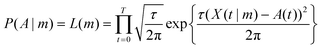 | (4) |
 | (5) |
 | (6) |
 | (7) |
 | (8) |
Outputs of the algorithm were the Markov chains for each fitted parameter. A value after which the Markov chain was considered to be stabilized was chosen (the ‘burn-in’) and the mean and the standard deviation of the stabilized section of the chain were calculated to determine the estimated parameter value and error respectively. An additional output was a list of values of likelihood at each step. An overlay of the experimental and fitted data was plotted. Convergence was ascertained by visual inspection of plots of the Markov chains (Fig. S3, ESI†).
Spectra were normalized before fitting to have a maximum value of 1. This was to avoid the need for large changes in input parameters between spectra, which would have slowed the fitting process. The scaling factors of the output were then divided by the normalization factor to give the result. Selected cases showed the algorithm to be robust to variations of initial values (not shown). In the rare cases where fitting did not converge, either the step size was increased or more algorithm steps were added.
Results
The results given below first show why we used ASTRID for this work and indicate what to look for when choosing to use a bench top instrument. We then probed the effect of stabilizing DNA duplexes by increasing the salt concentration and destabilizing them by increasing the temperature. The paper concludes with our deconvolution of the spectra as outlined in the methods section and the consequent analysis of the data.SRLD of DNA
We have previously shown that it is possible to collect DNA LD at ASTRID with our microvolume Couette flow cells down to the quartz cut-off of the cell (∼182 nm).9 Although the same wavelength range is possible on some bench top instruments the quality varies, as shown in Fig. 1 where LD spectra collected at ASTRID, on a Jasco J-815 and a Biologic MOS-450 (with very old mirrors) are overlaid. The spectra shown in Fig. 1 were all collected on a DNA with a large signal; data collection times and band widths were approximately 6 minutes/1 nm band width on ASTRID, 8 minutes/1 nm bandwidth on the J-815, and 6 minutes/4 nm band width on the unoptimised MOS-450.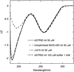 | ||
| Fig. 1 LD of DNA from M. luteus (concentrations as indicated) scaled to 1 at 260 nm in water and in buffer (1 mM cacodylate pH = 7) measured on three spectrometers: an unoptimised Biologic MOS-450 spectrometer (4 nm bandwidth); a Jasco J-815 (1 nm bandwidth), one of the latest spectrometers available; and the ASTRID UV1 synchrotron beamline (1 nm bandwidth). | ||
The effect of salt on DNA LD
High quality LD spectra for seven types of DNA as a function of NaF concentration are shown in Fig. 2 (poly[(dG-dC)]2 is overlaid on the M. luteusDNA spectra). To probe the extremes of behaviour, spectra were collected with as low an ionic strength as possible (i.e. simply adding water to the DNA) and then adding known amounts of NaF. However, this raised concerns about whether the DNA structure was being affected by lack of buffer. To check this, spectra of DNA with 1 mM sodium cacodylate buffer, pH = 7, were collected. The DNAs in the presence of buffer gave the same spectral shapes as the same ionic strength NaF concentration spectra (data not shown).![LD
spectra (in terms of differential absorbance) of seven DNA types as a function of NaF concentration. Concentrations are indicated in the figure. Buffer denotes 1 mM sodium cacodylate. Spectra were measured in a 0.5 mm path length Couette flow cell spinning at ∼3000 rpm at 22 °C. Quartz cut-off for the sample capillary is at 182 nm in these spectra. The data are presented in order of decreasing GC content, as indicated: (a) M. luteus and poly[(dG-dC)]2, (b) calf thymus, (c) C. perfringens, (d) poly[d(A)]-polyd(T)], (e) poly[(dA-dT)]2, (f) poly[d(A)].](/image/article/2012/CP/c1cp22371b/c1cp22371b-f2.gif) | ||
| Fig. 2 LD spectra (in terms of differential absorbance) of seven DNA types as a function of NaF concentration. Concentrations are indicated in the figure. Buffer denotes 1 mM sodium cacodylate. Spectra were measured in a 0.5 mm path length Couette flow cell spinning at ∼3000 rpm at 22 °C. Quartz cut-off for the sample capillary is at 182 nm in these spectra. The data are presented in order of decreasing GC content, as indicated: (a) M. luteus and poly[(dG-dC)]2, (b) calf thymus, (c) C. perfringens, (d) poly[d(A)]-polyd(T)], (e) poly[(dA-dT)]2, (f) poly[d(A)]. | ||
All spectra show the familiar DNA band at around 260 nm, generally accepted to be due to π–π* transitions within the DNA bases. In addition, a band with a peak maximum below 190 nm is apparent for all types of DNAs. The different amounts of NaF have the effect of scaling the magnitude of the spectra, and inducing some changes in shape.
M. luteus as a function of ionic strength and poly[d(G-C)]2 show almost identically shaped simple spectra with two bands apparent at 256 nm and 184 nm, as shown in Fig. 2a and more clearly in the normalized spectra shown in Fig. S1a (ESI†) (the poly[d(G-C)]2 is short so its intensity is low). The ratio of the two bands is 2∶1. Poly[d(G-C)]2 has slightly more 184 nm intensity relative to its 256 nm band than M. luteus but the difference is small.
As the A-T base pairs percentage increased with calf thymus DNA, the long wavelength band shifted to 257/258 nm and at low salt there is a shoulder apparent at ∼206 nm. The magnitude of the 184 nm wavelength band, compared with that at ∼260 nm, is lower for the DNAs with a lower GC content. The decrease is approximately linear with percentage of AT. The spectral shapes change as the ionic strength increases: the 206 nm shoulder disappears, the 184 nm band further decreases relative to the 257 nm region (see Fig. S1b, ESI†), and the longer wavelength band shifts to longer wavelength.
The mixed sequence, but even lower GG content C. perfringens, behaves similarly to calf thymus DNA though its long wavelength band moves from 257 nm to 260 nm as the salt concentration increases (Fig. 2c).
The poly[(dA)-(dT)]2 (Fig. 2d) spectra have a relatively lower intensity peak at 186 nm, a shoulder from 196 nm–205 nm, and a peak at 257 nm. Its spectra show little shape change as a function of ionic strength. The alternating DNA poly[(dA-dT)]2 (Fig. 2e) is similar to the non-alternating polymer but with an even more pronounced shoulder or peak from 190 nm–210 nm and even less intensity in the 184 nm band.
To compare the results for double stranded DNA with single stranded DNA, the LD of poly[(dA)] was also measured (Fig. 2(f)). The spectral shape exhibited by poly[d(A)] has similar features to those observed for poly[(dA)]-poly[d(T)] (Fig. 2(d)). Poly[d(G)] DNA was also tested, but did not align sufficiently in the flow cell to give a meaningful LD signal (Fig 2a).
The effect of increasing temperature on DNA LD
To achieve a destabilising effect on the DNA, in contrast with the stabilising effect of the salt summarised in Fig. 2, we measured LD as a function of temperature (but remained below the melting temperature) for four of the DNAs. The data are shown in Fig. 3. The most obvious change is the reduction in LD magnitude with increasing temperature. This is partly due to increased DNA flexibility and partly due to the reduction in the viscosity of water (by a factor of 2).35 The shape changes that occur as a function of temperature are clearer in the data that have been scaled to 1 at 260 nm (a fairly arbitrary choice) as summarised in Fig. S2 (ESI†).![LD
spectra in water as a function of temperature (indicated in each figure) of (a) M. luteus (100 μM), (b) calf thymus (200 μM), (c) poly[(dA-dT)]2 (200 μM) and (d) poly[d(A)] (200 μM) in a 0.5 mm pathlength Couette flow cell spinning at ∼3000 rpm. DNA concentrations were 200 μM. Quartz cut-off for sample capillary is at 182 nm in these spectra.](/image/article/2012/CP/c1cp22371b/c1cp22371b-f3.gif) | ||
| Fig. 3 LD spectra in water as a function of temperature (indicated in each figure) of (a) M. luteus (100 μM), (b) calf thymus (200 μM), (c) poly[(dA-dT)]2 (200 μM) and (d) poly[d(A)] (200 μM) in a 0.5 mm pathlength Couette flow cell spinning at ∼3000 rpm. DNA concentrations were 200 μM. Quartz cut-off for sample capillary is at 182 nm in these spectra. | ||
Quantitation of LD spectral changes by curve fitting
To probe the effects observed in the spectra more quantitatively, the LD spectra were fitted as a series of peaks with some functional form with an MCMC algorithm, as described above. The quality of the Lorentzian fitting (see eqn (8)) was significantly worse than that with Gaussian bands (eqn (7)), so only Gaussian results are shown (Fig. S4, ESI†).The algorithm was implemented using Python 2.6 (code available on request), including Numpy 1.5.1 and Scipy 0.8. One point of note is that the values produced for the Γ distribution (used in the Gibbs algorithm) from the Numpy random module were not reliable, and instead a version based on that reported in ref. 36 was used.
To speed the fitting process, initial inputs to the algorithm were found from either a rough fitting (large step size) or manually changing parameters. Selected cases showed that the algorithm was robust to starting values and choice of step size. This is an important point, since previous fitting algorithms17 have required a choice of initial value close to the output value and/or stopping before over-fitting occurred. After fitting, plots of the Markov chain and overlays of the experimental and model data were inspected for divergence.
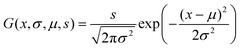
Each LD spectrum was individually modelled as a sum of Gaussian curves after the wavelength was converted to inverse wavelength (energy). Where three peaks were used, 9 parameters were required per spectrum: peak position in inverse wavelength (μ1, μ2, μ3), peak widths (also in inverse wavelength) (σ1, σ2, σ3) and (s1, s2, s3), which is related to the maximum amplitude
 | (9) |
Data were fitted in two different ways. Firstly, spectra were fitted separately, with all parameters local to each data set. Secondly, a global fit was undertaken. In each case the quoted errors are the standard deviation, so twice the quoted error gives the 95% confidence interval. 2, 3, 4 and 5 peaks were used to fit the data. For the majority of data sets 4 peaks provided the best fitting. The fits are summarized in Tables 2 and 3.
| DNA | Salt/mM | σ 1/nm | s 1 | Height 1 | σ 2/nm | s 2 | Height 2 |
|---|---|---|---|---|---|---|---|
| Poly(dA) | 0 | 12.21 ± 0.26 | 0.00746 ± 1.7 × 10⁻⁴ | 7.96 × 10⁻⁶ | 8.75 ± 0.13 | 0.002654 ± 7.3 × 10⁻⁵ | 5.51 × 10⁻⁶ |
| Poly(dA) | 0.025 | 13.1 ± 0.43 | 0.003445 ± 9.8 × 10⁻⁵ | 3.19 × 10⁻⁶ | 6.85 ± 0.22 | 6.96 × 10⁻⁴ ± 4.7 × 10⁻⁵ | 2.36 × 10⁻⁶ |
| Poly(dA) | 0.05 | 14.61 ± 0.55 | 0.002374 ± 8.5 × 10⁻⁵ | 1.77 × 10⁻⁶ | 6.85 ± 0.25 | 4.84 × 10⁻⁴ ± 4.0 × 10⁻⁵ | 1.64 × 10⁻⁶ |
| Poly(dA) | 0.075 | 10.0 ± 0.26 | 0.001811 ± 4.7 × 10⁻⁵ | 2.89 × 10⁻⁶ | 8.18 ± 0.22 | 7.78 × 10⁻⁴ ± 2.5 × 10⁻⁵ | 1.85 × 10⁻⁶ |
| Poly(dA) | 0.2 | 11.23 ± 0.51 | 0.001033 ± 4.3 × 10⁻⁵ | 1.3 × 10⁻⁶ | 9.92 ± 0.5 | 4.77 × 10⁻⁴ ± 2.8 × 10⁻⁵ | 7.7 × 10⁻⁷ |
| Poly(dA) | 1 | 21.1 ± 1.9 | 8.6 × 10⁻⁴ ± 1.1 × 10⁻⁴ | 3.07 × 10⁻⁷ | 18.2 ± 3.0 | 2.65 × 10⁻⁴ ± 6.8 × 10⁻⁵ | 1.27 × 10⁻⁷ |
| Poly[(dA-dT)]2 | 0 | 10.74 ± 0.29 | 0.002835 ± 8.2 × 10⁻⁵ | 3.91 × 10⁻⁶ | 11.91 ± 0.18 | 0.002944 ± 4.9 × 10⁻⁵ | 3.3 × 10⁻⁶ |
| Poly[(dA-dT)]2 | 5 | 11.53 ± 0.32 | 0.00372 ± 1.0 × 10⁻⁴ | 4.45 × 10⁻⁶ | 12.26 ± 0.19 | 0.00342 ± 6.1 × 10⁻⁵ | 3.62 × 10⁻⁶ |
| Poly[(dA-dT)]2 | 20 | 11.6 ± 0.34 | 0.00463 ± 1.4 × 10⁻⁴ | 5.48 × 10⁻⁶ | 11.99 ± 0.18 | 0.004178 ± 7.3 × 10⁻⁵ | 4.62 × 10⁻⁶ |
| Poly(dA-dT) | 0 | 11.59 ± 0.24 | 0.01526 ± 3.2 × 10⁻⁴ | 1.81 × 10⁻⁵ | 8.37 ± 0.1 | 0.00585 ± 1.4 × 10⁻⁴ | 1.33 × 10⁻⁵ |
| Poly(dA-dT) | 0.1 | 10.66 ± 0.21 | 0.00906 ± 1.9 × 10⁻⁴ | 1.27 × 10⁻⁵ | 8.72 ± 0.11 | 0.004164 ± 8.1 × 10⁻⁵ | 8.72 × 10⁻⁶ |
| Poly(dA-dT) | 0.2 | 12.41 ± 0.3 | 0.00669 ± 1.5 × 10⁻⁴ | 6.92 × 10⁻⁶ | 7.66 ± 0.12 | 0.001931 ± 6.8 × 10⁻⁵ | 5.23 × 10⁻⁶ |
| Poly(dA-dT) | 0.5 | 13.25 ± 0.36 | 0.00431 ± 1.0 × 10⁻⁴ | 3.91 × 10⁻⁶ | 7.51 ± 0.14 | 0.001015 ± 5.0 × 10⁻⁵ | 2.87 × 10⁻⁶ |
| C. perfringens | 0 | 10.96 ± 0.17 | 0.01274 ± 2.4 × 10⁻⁴ | 1.69 × 10⁻⁵ | 11.24 ± 0.15 | 0.00672 ± 1.1 × 10⁻⁴ | 8.47 × 10⁻⁶ |
| C. perfringens | 0.1 | 12.0 ± 0.2 | 0.01355 ± 2.5 × 10⁻⁴ | 1.5 × 10⁻⁵ | 11.17 ± 0.15 | 0.00576 ± 1.1 × 10⁻⁴ | 7.35 × 10⁻⁶ |
| C. perfringens | 0.2 | 12.93 ± 0.3 | 0.01474 ± 3.2 × 10⁻⁴ | 1.4 × 10⁻⁵ | 10.24 ± 0.19 | 0.00397 ± 1.5 × 10⁻⁴ | 6.03 × 10⁻⁶ |
| C. perfringens | 0.5 | 13.33 ± 0.37 | 0.01734 ± 4.4 × 10⁻⁴ | 1.55 × 10⁻⁵ | 12.78 ± 0.26 | 0.00884 ± 2.1 × 10⁻⁴ | 8.62 × 10⁻⁶ |
| Calf thymus | 0 | 11.31 ± 0.17 | 0.03777 ± 6.8 × 10⁻⁴ | 4.7 × 10⁻⁵ | 11.2 ± 0.18 | 0.0153 ± 3.1 × 10⁻⁴ | 1.94 × 10⁻⁵ |
| Calf thymus | 0.1 | 11.72 ± 0.18 | 0.05523 ± 9.5 × 10⁻⁴ | 6.4 × 10⁻⁵ | 11.4 ± 0.19 | 0.0216 ± 4.4 × 10⁻⁴ | 2.65 × 10⁻⁵ |
| Calf thymus | 0.15 | 12.41 ± 0.23 | 0.0708 ± 0.0014 | 7.32 × 10⁻⁵ | 11.85 ± 0.2 | 0.0318 ± 6.8 × 10⁻⁴ | 3.6 × 10⁻⁵ |
| Calf thymus | 0.2 | 12.73 ± 0.2 | 0.0735 ± 0.0013 | 7.23 × 10⁻⁵ | 12.19 ± 0.19 | 0.02983 ± 5.7 × 10⁻⁴ | 3.2 × 10⁻⁵ |
| Calf thymus | 0.25 | 12.86 ± 0.23 | 0.0724 ± 0.0014 | 6.97 × 10⁻⁵ | 12.3 ± 0.23 | 0.02928 ± 6.8 × 10⁻⁴ | 3.08 × 10⁻⁵ |
| Calf thymus | 0.5 | 11.25 ± 0.16 | 0.05753 ± 9.9 × 10⁻⁴ | 7.23 × 10⁻⁵ | 11.36 ± 0.18 | 0.02407 ± 4.4 × 10⁻⁴ | 2.97 × 10⁻⁵ |
| Calf thymus | 1 | 13.14 ± 0.26 | 0.0583 ± 0.0012 | 5.37 × 10⁻⁵ | 12.51 ± 0.25 | 0.02282 ± 5.6 × 10⁻⁴ | 2.32 × 10⁻⁵ |
| M. luteus | 0 | 12.36 ± 0.2 | 0.0943 ± 0.0016 | 9.83 × 10⁻⁵ | 11.05 ± 0.24 | 0.02469 ± 7.1 × 10⁻⁴ | 3.22 × 10⁻⁵ |
| M. luteus | 0.025 | 12.34 ± 0.18 | 0.0827 ± 0.0014 | 8.64 × 10⁻⁵ | 11.15 ± 0.23 | 0.02263 ± 6.0 × 10⁻⁴ | 2.9 × 10⁻⁵ |
| M. luteus | 0.05 | 12.3 ± 0.2 | 0.078 ± 0.0014 | 8.2 × 10⁻⁵ | 11.08 ± 0.24 | 0.02129 ± 6.2 × 10⁻⁴ | 2.76 × 10⁻⁵ |
| M. luteus | 0.2 | 12.49 ± 0.19 | 0.0776 ± 0.0013 | 7.92 × 10⁻⁵ | 11.24 ± 0.27 | 0.01948 ± 6.0 × 10⁻⁴ | 2.45 × 10⁻⁵ |
| M. luteus | 0.5 | 12.37 ± 0.2 | 0.0657 ± 0.0011 | 6.83 × 10⁻⁵ | 11.02 ± 0.25 | 0.01698 ± 4.7 × 10⁻⁴ | 2.22 × 10⁻⁵ |
| σ 3/nm | s 3 | Height 3 | σ 4/nm | s 4 | Height 4 | ||
|---|---|---|---|---|---|---|---|
| Poly(dA) | 0 | 12.74 ± 0.15 | 0.004325 ± 4.4 × 10⁻⁵ | 4.24 × 10⁻⁶ | 4.9 ± 0.71 | 1.414543 × 10⁻⁴ ± 0.0 | 9.39 × 10⁻⁷ |
| Poly(dA) | 0.025 | 10.8 ± 0.15 | 0.002072 ± 2.6 × 10⁻⁵ | 2.83 × 10⁻⁶ | 5.5 ± 0.46 | 1.792944 × 10⁻⁴ ± 0.0 | 9.42 × 10⁻⁷ |
| Poly(dA) | 0.05 | 10.95 ± 0.15 | 0.001746 ± 2.1 × 10⁻⁵ | 2.32 × 10⁻⁶ | 6.67 ± 0.44 | 2.114124 × 10⁻⁴ ± 0.0 | 7.56 × 10⁻⁷ |
| Poly(dA) | 0.075 | 10.33 ± 0.32 | 7.63 × 10⁻⁴ ± 2.2 × 10⁻⁵ | 1.14 × 10⁻⁶ | 9.3 ± 1.3 | 1.601932 × 10⁻⁴ ± 0.0 | 2.97 × 10⁻⁷ |
| Poly(dA) | 0.2 | 15.49 ± 0.97 | 4.65 × 10⁻⁴ ± 3.4 × 10⁻⁵ | 3.09 × 10⁻⁷ | 32.0 ± 11.0 | 8.4306 × 10⁻⁵ ± 0.0 | 1.35 × 10⁻⁸ |
| Poly(dA) | 1 | 16.4 ± 1.4 | 3.58 × 10⁻⁴ ± 4.3 × 10⁻⁵ | 2.13 × 10⁻⁷ | 46.0 ± 20.0 | 1.040192 × 10⁻⁴ ± 0.0 | 7.94 × 10⁻⁹ |
| Poly[(dA-dT)]2 | 0 | 11.48 ± 0.21 | 0.00221 ± 3.8 × 10⁻⁵ | 2.67 × 10⁻⁶ | 9.39 ± 0.29 | 9.309178 × 10⁻⁴ ± 0.0 | 1.68 × 10⁻⁶ |
| Poly[(dA-dT)]2 | 5 | 11.85 ± 0.24 | 0.002442 ± 4.4 × 10⁻⁵ | 2.77 × 10⁻⁶ | 9.69 ± 0.33 | 9.893741 × 10⁻⁴ ± 0.0 | 1.68 × 10⁻⁶ |
| Poly[(dA-dT)]2 | 20 | 11.31 ± 0.2 | 0.003107 ± 5.2 × 10⁻⁵ | 3.86 × 10⁻⁶ | 9.43 ± 0.26 | 0.0013667016 ± 0.0 | 2.45 × 10⁻⁶ |
| Poly(dA-dT) | 0 | 12.106 ± 0.098 | 0.010485 ± 7.4 × 10⁻⁵ | 1.14 × 10⁻⁵ | 5.85 ± 0.43 | 5.672972 × 10⁻⁴ ± 0.0 | 2.64 × 10⁻⁶ |
| Poly(dA-dT) | 0.1 | 12.86 ± 0.14 | 0.006794 ± 6.5 × 10⁻⁵ | 6.54 × 10⁻⁶ | 6.31 ± 0.84 | 3.163029 × 10⁻⁴ ± 0.0 | 1.26 × 10⁻⁶ |
| Poly(dA-dT) | 0.2 | 11.17 ± 0.11 | 0.003945 ± 3.6 × 10⁻⁵ | 5.03 × 10⁻⁶ | 6.29 ± 0.38 | 3.442592 × 10⁻⁴ ± 0.0 | 1.38 × 10⁻⁶ |
| Poly(dA-dT) | 0.5 | 10.8 ± 0.11 | 0.002318 ± 2.2 × 10⁻⁵ | 3.16 × 10⁻⁶ | 7.17 ± 0.3 | 3.485808 × 10⁻⁴ ± 0.0 | 1.08 × 10⁻⁶ |
| C. perfringens | 0 | 12.98 ± 0.15 | 0.008852 ± 9.6 × 10⁻⁵ | 8.36 × 10⁻⁶ | 8.67 ± 0.35 | 0.0014874667 ± 0.0 | 3.15 × 10⁻⁶ |
| C. perfringens | 0.1 | 12.5 ± 0.12 | 0.008607 ± 8.0 × 10⁻⁵ | 8.76 × 10⁻⁶ | 8.59 ± 0.24 | 0.0016854083 ± 0.0 | 3.64 × 10⁻⁶ |
| C. perfringens | 0.2 | 11.44 ± 0.11 | 0.007917 ± 7.9 × 10⁻⁵ | 9.63 × 10⁻⁶ | 8.65 ± 0.2 | 0.0023239896 ± 0.0 | 4.95 × 10⁻⁶ |
| C. perfringens | 0.5 | 12.99 ± 0.16 | 0.01207 ± 1.4 × 10⁻⁴ | 1.14 × 10⁻⁵ | 9.54 ± 0.22 | 0.0033313735 ± 0.0 | 5.82 × 10⁻⁶ |
| Calf thymus | 0 | 14.78 ± 0.17 | 0.02571 ± 2.9 × 10⁻⁴ | 1.87 × 10⁻⁵ | 10.24 ± 0.67 | 0.0030003888 ± 0.0 | 4.56 × 10⁻⁶ |
| Calf thymus | 0.1 | 14.61 ± 0.17 | 0.03561 ± 4.0 × 10⁻⁴ | 2.66 × 10⁻⁵ | 9.8 ± 0.48 | 0.0045224364 ± 0.0 | 7.49 × 10⁻⁶ |
| Calf thymus | 0.15 | 15.5 ± 0.18 | 0.04971 ± 6.0 × 10⁻⁴ | 3.29 × 10⁻⁵ | 10.81 ± 0.47 | 0.0072015941 ± 0.0 | 9.82 × 10⁻⁶ |
| Calf thymus | 0.2 | 14.76 ± 0.14 | 0.04776 ± 4.8 × 10⁻⁴ | 3.49 × 10⁻⁵ | 10.24 ± 0.33 | 0.0079271465 ± 0.0 | 1.2 × 10⁻⁵ |
| Calf thymus | 0.25 | 14.54 ± 0.17 | 0.04682 ± 5.4 × 10⁻⁴ | 3.52 × 10⁻⁵ | 10.2 ± 0.34 | 0.0085508571 ± 0.0 | 1.31 × 10⁻⁵ |
| Calf thymus | 0.5 | 14.61 ± 0.16 | 0.03935 ± 4.0 × 10⁻⁴ | 2.94 × 10⁻⁵ | 10.38 ± 0.51 | 0.0056746505 ± 0.0 | 8.38 × 10⁻⁶ |
| Calf thymus | 1 | 14.32 ± 0.17 | 0.0364 ± 4.0 × 10⁻⁴ | 2.82 × 10⁻⁵ | 10.01 ± 0.3 | 0.0071018423 ± 0.0 | 1.13 × 10⁻⁵ |
| M. luteus | 0 | 17.18 ± 0.17 | 0.06394 ± 6.4 × 10⁻⁴ | 3.45 × 10⁻⁵ | 10.49 ± 0.83 | 0.0041447972 ± 0.0 | 5.99 × 10⁻⁶ |
| M. luteus | 0.025 | 17.24 ± 0.17 | 0.05702 ± 5.8 × 10⁻⁴ | 3.05 × 10⁻⁵ | 10.28 ± 0.82 | 0.0034964863 ± 0.0 | 5.27 × 10⁻⁶ |
| M. luteus | 0.05 | 17.3 ± 0.18 | 0.05355 ± 6.0 × 10⁻⁴ | 2.85 × 10⁻⁵ | 10.45 ± 0.88 | 0.0032385772 ± 0.0 | 4.72 × 10⁻⁶ |
| M. luteus | 0.2 | 16.78 ± 0.18 | 0.0525 ± 6.2 × 10⁻⁴ | 2.97 × 10⁻⁵ | 10.73 ± 0.8 | 0.0041981399 ± 0.0 | 5.8 × 10⁻⁶ |
| M. luteus | 0.5 | 17.04 ± 0.17 | 0.04379 ± 4.7 × 10⁻⁴ | 2.4 × 10⁻⁵ | 10.32 ± 0.82 | 0.0028886551 ± 0.0 | 4.32 × 10⁻⁶ |
| DNA | Salt/mM | μ 1/nm | σ 1/nm | s 1 | Height 1 | μ 2/nm | σ 2/nm | s 2 | Height 2 |
|---|---|---|---|---|---|---|---|---|---|
| Poly(dA) | 0 | 185.0 ± 0.12 | 4.87 ± 0.29 | 0.00199 ± 2.4 × 10⁻⁴ | 1.34 × 10⁻⁵ | 200.1 ± 0.7 | 11.9 ± 0.49 | 0.00533 ± 2.8 × 10⁻⁴ | 5.99 × 10⁻⁶ |
| Poly(dA) | 0.025 | 185.49 ± 0.52 | 4.25 ± 0.48 | 0.00102 ± 3.1 × 10⁻⁴ | 8.98 × 10⁻⁶ | 199.3 ± 1.5 | 12.86 ± 0.84 | 0.00377 ± 9.5 × 10⁻⁴ | 3.62 × 10⁻⁶ |
| Poly(dA) | 0.05 | 185.94 ± 0.32 | 3.18 ± 0.33 | 3.86 × 10⁻⁴ ± 5.7 × 10⁻⁵ | 6.07 × 10⁻⁶ | 200.01 ± 0.73 | 10.02 ± 0.49 | 0.001356 ± 7.4 × 10⁻⁵ | 2.15 × 10⁻⁶ |
| Poly(dA) | 0.075 | 186.47 ± 0.31 | 5.43 ± 0.38 | 8.77 × 10⁻⁴ ± 8.0 × 10⁻⁵ | 4.73 × 10⁻⁶ | 204.82 ± 0.84 | 9.07 ± 0.64 | 9.83 × 10⁻⁴ ± 7.6 × 10⁻⁵ | 1.9 × 10⁻⁶ |
| Poly(dA) | 0.2 | 185.7 ± 2.1 | −11.6 ± 6.2 | 8.0 × 10⁻⁴ ± 5.0 × 10⁻⁴ | 9.42 × 10⁻⁷ | 193.0 ± 15.0 | 17.9 ± 8.7 | 6.1 × 10⁻⁴ ± 3.7 × 10⁻⁴ | 3.05 × 10⁻⁷ |
| Poly(dA) | 1 | 187.55 ± 0.45 | 3.33 ± 0.56 | 7.8 × 10⁻⁵ ± 2.1 × 10⁻⁵ | 1.12 × 10⁻⁶ | 197.7 ± 2.2 | 14.8 ± 1.7 | 7.0 × 10⁻⁴ ± 1.1 × 10⁻⁴ | 5.12 × 10⁻⁷ |
| Poly[(dA-dT)]2 | 0 | 200.85 ± 0.84 | 14.96 ± 0.62 | 0.00418 ± 2.1 × 10⁻⁴ | 2.97 × 10⁻⁶ | 183.78 ± 0.26 | 5.27 ± 0.63 | 8.0 × 10⁻⁴ ± 1.7 × 10⁻⁴ | 4.61 × 10⁻⁶ |
| Poly[(dA-dT)]2 | 5 | 184.36 ± 0.22 | 3.42 ± 0.46 | 5.0 × 10⁻⁴ ± 1.1 × 10⁻⁴ | 6.8 × 10⁻⁶ | 198.8 ± 0.71 | 16.55 ± 0.55 | 0.00585 ± 2.2 × 10⁻⁴ | 3.4 × 10⁻⁶ |
| Poly[(dA-dT)]2 | 20 | 184.21 ± 0.18 | 3.91 ± 0.41 | 8.5 × 10⁻⁴ ± 1.4 × 10⁻⁴ | 8.84 × 10⁻⁶ | 200.46 ± 0.59 | 15.6 ± 0.5 | 0.00695 ± 2.4 × 10⁻⁴ | 4.54 × 10⁻⁶ |
| Poly(dA-dT) | 0 | 185.54 ± 0.17 | 4.74 ± 0.3 | 0.00453 ± 5.1 × 10⁻⁴ | 3.21 × 10⁻⁵ | 201.36 ± 0.67 | 10.95 ± 0.5 | 0.01034 ± 5.5 × 10⁻⁴ | 1.37 × 10⁻⁵ |
| Poly(dA-dT) | 0.1 | 185.47 ± 0.14 | 4.79 ± 0.24 | 0.00304 ± 2.6 × 10⁻⁴ | 2.1 × 10⁻⁵ | 201.93 ± 0.56 | 11.17 ± 0.43 | 0.00659 ± 2.9 × 10⁻⁴ | 8.41 × 10⁻⁶ |
| Poly(dA-dT) | 0.2 | 185.72 ± 0.16 | 4.71 ± 0.25 | 0.00189 ± 1.8 × 10⁻⁴ | 1.36 × 10⁻⁵ | 201.12 ± 0.61 | 10.37 ± 0.43 | 0.00391 ± 1.9 × 10⁻⁴ | 5.78 × 10⁻⁶ |
| Poly(dA-dT) | 0.5 | 184.87 ± 0.16 | 5.03 ± 0.3 | 0.00121 ± 1.3 × 10⁻⁴ | 7.6 × 10⁻⁶ | 200.27 ± 0.68 | 10.56 ± 0.44 | 0.00243 ± 1.3 × 10⁻⁴ | 3.47 × 10⁻⁶ |
| C. perfringens | 0 | 185.44 ± 0.16 | 5.91 ± 0.38 | 0.00475 ± 7.1 × 10⁻⁴ | 2.16 × 10⁻⁵ | 201.1 ± 1.2 | 13.8 ± 0.82 | 0.01059 ± 8.9 × 10⁻⁴ | 8.85 × 10⁻⁶ |
| C. perfringens | 0.1 | 185.83 ± 0.19 | 5.64 ± 0.45 | 0.00408 ± 7.4 × 10⁻⁴ | 2.04 × 10⁻⁵ | 199.9 ± 1.3 | 13.61 ± 0.76 | 0.01041 ± 9.1 × 10⁻⁴ | 8.95 × 10⁻⁶ |
| C. perfringens | 0.2 | 185.75 ± 0.2 | 6.1 ± 0.49 | 0.00431 ± 8.3 × 10⁻⁴ | 1.85 × 10⁻⁵ | 199.2 ± 1.5 | 12.66 ± 0.73 | 0.00888 ± 9.5 × 10⁻⁴ | 8.82 × 10⁻⁶ |
| C. perfringens | 0.5 | 186.18 ± 0.25 | 5.03 ± 0.5 | 0.00357 ± 7.2 × 10⁻⁴ | 2.24 × 10⁻⁵ | 199.2 ± 1.0 | 14.63 ± 0.71 | 0.0164 ± 0.0012 | 1.22 × 10⁻⁵ |
| Calf thymus | 0 | 185.63 ± 0.16 | 5.44 ± 0.33 | 0.0106 ± 0.0014 | 5.72 × 10⁻⁵ | 198.0 ± 1.1 | 14.95 ± 0.69 | 0.0308 ± 0.0022 | 2.19 × 10⁻⁵ |
| Calf thymus | 0.1 | 185.73 ± 0.18 | 5.36 ± 0.42 | 0.0142 ± 0.0026 | 7.89 × 10⁻⁵ | 197.6 ± 1.4 | 15.06 ± 0.76 | 0.0455 ± 0.0038 | 3.19 × 10⁻⁵ |
| Calf thymus | 0.15 | 185.6 ± 0.19 | 4.91 ± 0.43 | 0.0149 ± 0.0027 | 9.84 × 10⁻⁵ | 197.7 ± 1.0 | 14.68 ± 0.69 | 0.064 ± 0.0043 | 4.73 × 10⁻⁵ |
| Calf thymus | 0.2 | 185.74 ± 0.2 | 5.64 ± 0.56 | 0.0191 ± 0.0043 | 9.59 × 10⁻⁵ | 198.5 ± 1.5 | 14.37 ± 0.86 | 0.0589 ± 0.0058 | 4.54 × 10⁻⁵ |
| Calf thymus | 0.25 | 185.73 ± 0.23 | 5.33 ± 0.52 | 0.016 ± 0.0035 | 8.98 × 10⁻⁵ | 197.5 ± 1.3 | 14.81 ± 0.75 | 0.0615 ± 0.0051 | 4.46 × 10⁻⁵ |
| Calf thymus | 0.5 | 185.65 ± 0.17 | 5.52 ± 0.33 | 0.0171 ± 0.0023 | 8.91 × 10⁻⁵ | 198.5 ± 1.1 | 14.8 ± 0.71 | 0.0463 ± 0.0033 | 3.37 × 10⁻⁵ |
| Calf thymus | 1 | 185.72 ± 0.21 | 5.24 ± 0.43 | 0.012 ± 0.002 | 6.95 × 10⁻⁵ | 197.12 ± 0.96 | 14.55 ± 0.52 | 0.0487 ± 0.0029 | 3.66 × 10⁻⁵ |
| M. luteus | 0 | 151.93 ± 0.91 | 32.1 ± 0.67 | 0.2472 ± 0.005 | 3.82 × 10⁻⁵ | 175.3 ± 3.5 | 23.3 ± 2.2 | 0.085 ± 0.011 | 2.51 × 10⁻⁵ |
| M. luteus | 0.025 | 140.46 ± 0.2 | 62.46 ± 0.2 | 0.0146 ± 0.0016 | 5.97 × 10⁻⁷ | 168.0 ± 0.59 | 26.68 ± 0.36 | 0.2179 ± 0.0018 | 4.87 × 10⁻⁵ |
| M. luteus | 0.05 | 175.82 ± 0.23 | 13.03 ± 0.24 | 0.0741 ± 0.0018 | 6.94 × 10⁻⁵ | 197.4 ± 0.66 | 16.31 ± 0.42 | 0.0477 ± 0.0024 | 2.86 × 10⁻⁵ |
| M. luteus | 0.2 | 162.83 ± 0.25 | 22.82 ± 0.22 | 0.1057 ± 0.0017 | 3.23 × 10⁻⁵ | 177.36 ± 0.67 | 24.01 ± 0.4 | 0.0933 ± 0.0027 | 2.58 × 10⁻⁵ |
| M. luteus | 0.5 | 132.22 ± 0.24 | −8.69 ± 0.25 | 0.088 ± 0.0016 | 1.86 × 10⁻⁴ | 167.84 ± 0.7 | 26.42 ± 0.39 | 0.1794 ± 0.0018 | 4.09 × 10⁻⁵ |
| μ 3/nm | σ 3/nm | s 3 | Height 3 | μ 4/nm | σ 4/nm | s 4 | Height 4 | ||
|---|---|---|---|---|---|---|---|---|---|
| Poly(dA) | 0 | 256.41 ± 0.56 | −12.08 ± 0.47 | 0.0041 ± 1.9 × 10⁻⁴ | 4.47 × 10⁻⁶ | 277.7 ± 2.8 | 7.9 ± 3.0 | 3.3 × 10⁻⁴ ± 1.7 × 10⁻⁴ | 8.65 × 10⁻⁷ |
| Poly(dA) | 0.025 | 256.94 ± 0.67 | −13.8 ± 1.1 | 0.0029 ± 5.1 × 10⁻⁴ | 2.44 × 10⁻⁶ | 190.0 ± 23.0 | 38.0 ± × 10.0 | −0.0052 ± 0.0021 | −5.81 × 10⁻⁷ |
| Poly(dA) | 0.05 | 257.6 ± 1.2 | −11.7 ± 1.1 | 0.00181 ± 2.4 × 10⁻⁴ | 2.1 × 10⁻⁶ | 268.0 ± 11.0 | 19.0 ± 15.0 | 1.1 × 10⁻⁴ ± 2.9 × 10⁻⁴ | 4.67 × 10⁻⁸ |
| Poly(dA) | 0.075 | 258.7 ± 1.3 | −11.8 ± 1.1 | 8.2 × 10⁻⁴ ± 1.4 × 10⁻⁴ | 9.46 × 10⁻⁷ | 278.0 ± 13.0 | 38.0 ± 18.0 | 1.0 × 10⁻⁴ ± 1.5 × 10⁻⁴ | 1.12 × 10⁻⁸ |
| Poly(dA) | 0.2 | 259.1 ± 1.2 | −14.6 ± 1.5 | 4.46 × 10⁻⁴ ± 6.1 × 10⁻⁵ | 3.33 × 10⁻⁷ | 241.0 ± 22.0 | 70.0 ± 18.0 | 1.3 × 10⁻⁴ ± 1.8 × 10⁻⁴ | 4.35 × 10⁻⁹ |
| Poly(dA) | 1 | 171.0 ± 29.0 | −28.7 ± 7.8 | −6.9 × 10⁻⁴ ± 5.0 × 10⁻⁴ | −1.33 × 10⁻⁷ | 254.4 ± 1.4 | 21.5 ± 1.2 | 5.13 × 10⁻⁴ ± 4.2 × 10⁻⁵ | 1.77 × 10⁻⁷ |
| Poly[(dA-dT)]2 | 0 | 258.8 ± 1.1 | −11.77 ± 0.75 | 0.00218 ± 2.1 × 10⁻⁴ | 2.5 × 10⁻⁶ | 279.4 ± 1.6 | 8.57 ± 0.91 | 6.8 × 10⁻⁴ ± 2.0 × 10⁻⁴ | 1.48 × 10⁻⁶ |
| Poly[(dA-dT)]2 | 5 | 257.2 ± 1.7 | −11.22 ± 0.9 | 0.00223 ± 3.7 × 10⁻⁴ | 2.82 × 10⁻⁶ | 277.3 ± 2.6 | 9.9 ± 1.3 | 0.0011 ± 3.6 × 10⁻⁴ | 1.79 × 10⁻⁶ |
| Poly[(dA-dT)]2 | 20 | 258.1 ± 1.6 | −11.37 ± 0.89 | 0.00336 ± 4.8 × 10⁻⁴ | 4.14 × 10⁻⁶ | 278.2 ± 2.3 | 9.1 ± 1.1 | 0.00133 ± 4.6 × 10⁻⁴ | 2.57 × 10⁻⁶ |
| Poly(dA-dT) | 0 | 254.2 ± 1.2 | −8.4 ± 2.1 | 0.0031 ± 0.0025 | 6.88 × 10⁻⁶ | 260.8 ± 3.3 | 13.66 ± 0.85 | 0.008 ± 0.0025 | 6.86 × 10⁻⁶ |
| Poly(dA-dT) | 0.1 | 254.72 ± 0.99 | −8.4 ± 2.4 | 0.0018 ± 0.0014 | 4.03 × 10⁻⁶ | 259.9 ± 2.3 | 14.77 ± 0.8 | 0.0054 ± 0.0014 | 3.93 × 10⁻⁶ |
| Poly(dA-dT) | 0.2 | 256.18 ± 0.96 | −10.59 ± 0.51 | 0.0036 ± 3.7 × 10⁻⁴ | 5.1 × 10⁻⁶ | 274.7 ± 3.0 | 7.9 ± 1.7 | 6.7 × 10⁻⁴ ± 3.6 × 10⁻⁴ | 1.68 × 10⁻⁶ |
| Poly(dA-dT) | 0.5 | 255.5 ± 1.2 | −9.87 ± 0.63 | 0.00192 ± 3.5 × 10⁻⁴ | 3.14 × 10⁻⁶ | 273.2 ± 3.5 | 9.1 ± 1.5 | 7.2 × 10⁻⁴ ± 3.5 × 10⁻⁴ | 1.37 × 10⁻⁶ |
| C. perfringens | 0 | 255.8 ± 1.4 | −12.11 ± 0.78 | 0.00793 ± 9.7 × 10⁻⁴ | 8.61 × 10⁻⁶ | 276.8 ± 2.7 | 9.7 ± 1.4 | 0.00235 ± 9.4 × 10⁻⁴ | 4.01 × 10⁻⁶ |
| C. perfringens | 0.1 | 256.3 ± 1.2 | −12.1 ± 0.74 | 0.00802 ± 8.0 × 10⁻⁴ | 8.72 × 10⁻⁶ | 276.8 ± 2.2 | 9.4 ± 1.2 | 0.00224 ± 7.8 × 10⁻⁴ | 4.02 × 10⁻⁶ |
| C. perfringens | 0.2 | 255.7 ± 1.7 | −10.81 ± 0.8 | 0.0068 ± 0.0012 | 9.22 × 10⁻⁶ | 274.9 ± 2.7 | 9.8 ± 1.2 | 0.0034 ± 0.0012 | 5.59 × 10⁻⁶ |
| C. perfringens | 0.5 | 260.8 ± 5.2 | −18.2 ± 8.4 | −0.0053 ± 0.004 | −2.55 × 10⁻⁶ | 261.36 ± 0.88 | 16.6 ± 1.4 | 0.0206 ± 0.0038 | 1.18 × 10⁻⁵ |
| Calf thymus | 0 | 261.25 ± 0.6 | −14.78 ± 0.55 | 0.0394 ± 0.0053 | 2.87 × 10⁻⁵ | 265.2 ± 1.1 | 10.2 ± 1.3 | −0.0109 ± 0.0054 | −1.68 × 10⁻⁵ |
| Calf thymus | 0.1 | 262.24 ± 0.66 | −13.86 ± 0.46 | 0.112 ± 0.011 | 9.31 × 10⁻⁵ | 263.38 ± 0.83 | 12.57 ± 0.62 | −0.073 ± 0.011 | −7.3 × 10⁻⁵ |
| Calf thymus | 0.15 | 261.5 ± 4.8 | −17.1 ± 5.1 | −0.006 ± 0.017 | −3.38 × 10⁻⁶ | 260.4 ± 1.3 | 17.0 ± 1.0 | 0.064 ± 0.016 | 3.51 × 10⁻⁵ |
| Calf thymus | 0.2 | 257.0 ± 1.8 | −15.1 ± 1.1 | 0.0482 ± 0.006 | 3.37 × 10⁻⁵ | 279.0 ± 3.3 | 9.6 ± 2.5 | 0.0079 ± 0.0057 | 1.37 × 10⁻⁵ |
| Calf thymus | 0.25 | 258.0 ± 1.6 | −15.35 ± 0.94 | 0.0502 ± 0.0054 | 3.39 × 10⁻⁵ | 280.9 ± 3.1 | 8.6 ± 2.1 | 0.0057 ± 0.0051 | 1.21 × 10⁻⁵ |
| Calf thymus | 0.5 | 256.5 ± 1.1 | −13.82 ± 0.79 | 0.0376 ± 0.0031 | 3.14 × 10⁻⁵ | 279.8 ± 2.4 | 9.6 ± 1.5 | 0.0071 ± 0.0029 | 1.22 × 10⁻⁵ |
| Calf thymus | 1 | 273.0 ± 11.0 | −29.0 ± 5.8 | −0.0032 ± 0.0031 | −6.12 × 10⁻⁷ | 260.33 ± 0.37 | 17.3 ± 0.42 | 0.0475 ± 0.003 | 2.52 × 10⁻⁵ |
| M. luteus | 0 | 256.0 ± 19.0 | −14.0 ± 7.5 | 0.0515 ± 0.0068 | 4.2 × 10⁻⁵ | 279.4 ± 1.9 | 10.4 ± 1.6 | 0.012 ± 0.014 | 1.76 × 10⁻⁵ |
| M. luteus | 0.025 | 256.2 ± 5.2 | −14.5 ± 1.9 | 0.048 ± 0.037 | 3.66 × 10⁻⁵ | 280.0 ± 15.0 | 10.1 ± 8.4 | 0.009 ± 0.037 | 1.42 × 10⁻⁵ |
| M. luteus | 0.05 | 256.65 ± 0.73 | −15.65 ± 0.9 | 0.0495 ± 0.0054 | 3.22 × 10⁻⁵ | 281.8 ± 9.6 | 9.0 ± 22.0 | 0.0055 ± 0.0069 | 1.08 × 10⁻⁵ |
| M. luteus | 0.2 | 256.2 ± 1.2 | −14.3 ± 0.56 | 0.0451 ± 0.003 | 3.51 × 10⁻⁵ | 280.05 ± 0.43 | 10.06 ± 0.47 | 0.0088 ± 0.0012 | 1.39 × 10⁻⁵ |
| M. luteus | 0.5 | 256.38 ± 0.56 | −14.47 ± 0.72 | 0.0376 ± 0.002 | 2.86 × 10⁻⁵ | 281.0 ± 12.0 | 10.0 ± 15.0 | 0.0065 ± 0.0047 | 1.11 × 10⁻⁵ |
Fitting of the lowest wavelength peak caused some difficulties. The peak lies very close to the cut-off value of the experimental data (due to impurities in the quartz, the sample holder cuts off absorbance below 182 nm). In some cases the location of the peak maximum is clearly shifted by several nanometres. By discarding data below the lowest wavelength peak (e.g. data below 184 nm for C. perfringensDNA with no salt), fitting was improved. In the separate fitting, described in the previous paragraph, M. luteus data could only be fit well with such a low wavelength cut-off; other data use the full data ranges as described in the methods section (Table 3). Global fitting, described above, was carried out with a low wavelength cut-off of the data (Table 2). Heights calculated using eqn (9) are also given.
Fitting with 5 peaks (Table 5 and Table S1 (ESI†)) gave a variety of peak positions that were not consistent, with results often out of the wavelength range or very close to other peaks. We thus concluded that the use of 5 peaks was over-fitting the data. The exception to this was poly(dA) at temperatures above 45 °C, where five peaks were more suitable. In this case two of the peaks were at similar positions with opposite magnitudes.
In general poly[d(A)] required peaks at 185, 200 and 257 nm. Addition of T required a longer wavelength peak at ∼278 nm. Significant G content required a peak at ∼190 nm.
In order to generate wavelength values that might be compared with theoretical predictions, the wavelengths were considered global to all data sets and other parameters local (Table 2), i.e. we allowed σ and s to differ for each spectrum and required the best wavelength for all spectra. The ‘global’ wavelengths generated by this method were 182 nm, 207 nm, 257 nm and 278 nm.
Discussion
Is SRLD required for low wavelength DNA spectra?
Similar signal:noise levels were achieved for the two bench top instruments and ASTRID with the high concentration sample we tested. However, a large bandwidth was required with the old mirrors of the MOS-450 to achieve this. More significant is the fact that the magnitudes and positions of lower wavelength intensities are not the same for the three instruments. We concluded that the ASTRID data are ‘true’ since only for this instrument was the same shaped spectrum observed when the concentration was significantly changed. The serious warning provided in Fig. 1 is that although the signal:noise with the unoptimised MOS-450 appears to be satisfactory, this is an illusion caused by stray light which increases the photon count, but with photons of the wrong wavelength. It thus provides a warning for low wavelength data collection. The Jasco J-815 instrument performs well, although there is a slight signal attenuation of the LD at lowest wavelengths shown in Fig. 1 and its signal:noise is not as good as ASTRID at lower concentrations (data not shown).Changes in LD spectra induced by stabilising the DNA with increased ionic strength
To change the LD spectrum of a molecule, the molecule must change its oscillator strength and/or the angles of transition moments relative to the orientation axis. The former is dependent on the local electronic environment and is affected by interactions such as π–π* stacking which induces hypochromism and red-shifting of bands.6 A change in chromophore angle (relative to the molecule) is likely to be due to a local structural change. The overall sample orientation, as summarized in the orientation parameter S of eqn (2), is dependent on both chemical environment and molecular structure and is manifest as a scaling of the whole spectrum.It is well known that positive ions condense onto DNA, although the precise mechanistic details and locations are still unclear.37 The main effect of salt on LD of DNA can be summarised as follows. The salt cations reduce the negative charge–charge repulsion interactions between DNA bases which creates an overall increase in DNA flexibility. This in turn leads to a reduction of the orientation of the molecules in flow and consequently reduces the observed LD magnitudes. We had therefore anticipated that the DNA LD signals would all decrease with increasing salt as charge neutralization reduced the phosphate–phosphate repulsion and increased DNA flexibility. Similarly, we expected the LD to decrease with increasing temperature as DNA flexibility increased and solvent viscosity decreased. In both cases, the main effect was expected to be via the orientation parameter. The decrease with increasing temperature was indeed observed, though generally not uniformly across the wavelength range. The expected salt dependence was not observed for calf thymus DNA and C. perfringens suggesting that for these DNAs other effects dominate the simple electrostatic effect described above.
The curve fitting results help us to quantify what is happening. We have determined the number of spectral peaks present in each spectrum, reaching an upper limit at which the model is overfitting the data. Verification of the quality of fitting was straightforward, as described in the methods section. The fitting confirms the salient points observable by inspection of Fig. 2 and 3 and, as discussed below, allows us to look at features such as spectral bandwidth which gives more information than available to the eye. By not incorporating a smoothing step, we are confident that the outputs are features of the ‘real’ spectra and are not altered by smoothing artefacts. Since the independent fitting shows no evidence of significant wavelength shifts beyond what was observable visually, the discussion below focuses on the global fitting data.
Changes in LD spectra induced by stabilising the DNA with increased salt
M. luteus DNA shows no change in bandwidths or relative intensities as the salt increases (Table 2 and Fig. 2a, and Fig. S1a (ESI†)). The same is approximately true for the bandwidths of poly[(dA)] and the A-T polymers within the experimental error, though Fig. S1 (ESI†) suggests that some relative tilting of bases is occurring.Calf thymus DNA (Table 2), on the other hand, shows an increase in 182 nm and 207 nm bandwidths with increasing salt as well as an increase in intensity with increasing salt for the low salt curves. The obvious signature of this in the spectra is the loss of the ∼205 nm shoulder. This implies that the shorter wavelength transitions are seeing increased base stacking with increasing salt. By way of contrast, the longer wavelength calf thymus Gaussians are of constant width (within error) suggesting no change in the stacking of these transitions. To understand this properly, we really need accurate transition moment polarizations. Fig. 4 contains what may be described as the best estimate from the literature, which unfortunately is restricted to high energies for adenine. The long wavelength transitions (assuming Fig. 4 is correct) are all approximately perpendicular to the bases, this suggests that it is the transitions along the base pair long axis of G, C and/or A which are seeing an increase in stacking with increasing salt, and it is this increase in base stacking that counters the expected salt-induced bending of DNA until the [NaF] reaches 0.2 M. This is discussed further below.
 | ||
| Fig. 4 (a) Probable transition polarizations for UV transitions of adenine, guanine, cytosine and thymine. The bases are drawn oriented so that the long axis of the DNA base pairs is horizontal. (b) UV spectra of the DNA nucleotides.17,40–43 | ||
The visually apparent shift to slightly longer wavelength in the scaled ct-DNA spectra shown in Fig. S1 (ESI†) is the result of a relative increase in magnitude of the small 278 nm band by 70%. Thus either the 257 nm band decreases (more π–π stacking) from 0 salt to 0.2 M salt or the 278 nm band increases (less π–π stacking). We cannot differentiate these from the LD since S is also changing. However, the long wavelength absorbance (data not shown) decreases in intensity with increasing salt which is consistent with increased π–π stacking.
C. perfringens is midway between calf thymus and poly[(dA-dT)]2 showing an increase in the 182 nm bandwidth and intensity; no change in 207 nm bandwidth but a decrease in its intensity and not much change at longer wavelength. The 207 nm region is a mix of long and short axis polarized transitions with increased short-axis contribution as the percentage of thymine is increased relative to calf thymus DNA.
Changes in LD spectra induced by destabilising the DNA with increased temperature
All DNAs showed changes in the LD as the helix is destabilised by raising the temperature. Most obviously the magnitudes decrease as the viscosity decreases and the DNA flexibility increases. In addition the 205 nm region shows a clear increase in or appearance of a shoulder in the 205 nm region. From the fixed wavelength fits (Table 4) we can deduce more about what is happening. The M. luteusDNA, for example, shows a narrowing of all bands consistent with a decrease in base stacking. In addition there is an increase in the magnitudes of all other bands relative to the 253 nm band, especially the 208 nm band for which the relative increase is 30%. Whether this is due to an increase in others or decrease in 253 nm is not apparent from the LD alone. We know that A260nm gradually increases with all DNA sequences (pre-transition baseline of all sequences in a standard DNA melting curve assay)38 as the DNA is warmed up, so we are in fact seeing an increase in all bands and a decrease in π–π stacking for all transitions with temperature. The fitting confirmed evidence of the appearance of a positive peak in the spectrum of poly[d(A)] above 40 °C (Tables 4 and 5, Fig. S5 (ESI†)). No other spectra showed evidence of a peak at this point in the spectrum.
| DNA | Temperature/°C | σ 1/nm | s 1 | Height 1 | σ 2/nm | s 2 | Height 2 |
|---|---|---|---|---|---|---|---|
| Poly(dA) | 35 | 15.05 ± 0.58 | 0.01083 ± 4.3 × 10⁻⁴ | 2.87 × 10⁻⁴ | 4.07 ± 0.79 | 3.2 × 10⁻⁴ ± 1.0 × 10⁻⁴ | 3.16 × 10⁻⁵ |
| Poly(dA) | 40 | 14.08 ± 0.43 | 0.00832 ± 2.9 × 10⁻⁴ | 2.36 × 10⁻⁴ | 3.7 ± 0.68 | 2.07 × 10⁻⁴ ± 5.6 × 10⁻⁵ | 2.23 × 10⁻⁵ |
| Poly(dA) | 45 | 15.59 ± 0.53 | 0.0061 ± 2.9 × 10⁻⁴ | 1.56 × 10⁻⁴ | 65.0 ± 15.0 | −0.0035 ± 0.0014 | −2.12 × 10⁻⁵ |
| Poly(dA) | 50 | −15.8 ± 2.9 | 0.00501 ± 8.0 × 10⁻⁴ | 1.27 × 10⁻⁴ | 25.2 ± 8.1 | −0.00114 ± 5.3 × 10⁻⁴ | −1.8 × 10⁻⁵ |
| Poly[(dAdT)]2 | 35 | 28.99 ± 0.82 | 0.1051 ± 0.0031 | 0.00145 | 4.46 ± 0.33 | 0.00647 ± 0.00063 | 5.79 × 10⁻⁴ |
| Poly[(dAdT)]2 | 40 | 9.84 ± 0.67 | 0.0329 ± 0.0024 | 0.00132 | 8.82 ± 0.47 | 0.0210 ± 0.0012 | 9.48 × 10⁻⁴ |
| Poly[(dAdT)]2 | 45 | −32.5 ± 6.6 | 0.0278 ± 0.0050 | 3.41 × 10⁻⁴ | 4.91 ± 0.73 | 0.0045 ± 0.0012 | 3.62 × 10⁻⁴ |
| Poly[(dAdT)]2 | 50 | −22.2 ± 5.2 | 0.0315 ± 0.0083 | 5.66 × 10⁻⁴ | −30.0 ± 14.0 | −0.0006 ± 0.0060 | −7.26 × 10⁻⁶ |
| Calf thymus | 30 | 11.45 ± 0.45 | 0.01828 ± 8.9 × 10⁻⁴ | 6.37 × 10⁻⁴ | 11.59 ± 0.57 | 0.00636 ± 3.4 × 10⁻⁴ | 2.19 × 10⁻⁴ |
| Calf thymus | 35 | 11.19 ± 0.41 | 0.01383 ± 6.6 × 10⁻⁴ | 4.93 × 10⁻⁴ | 11.06 ± 0.56 | 0.00476 ± 2.6 × 10⁻⁴ | 1.72 × 10⁻⁴ |
| Calf thymus | 40 | 10.59 ± 0.38 | 0.01055 ± 5.0 × 10⁻⁴ | 3.97 × 10⁻⁴ | 10.99 ± 0.54 | 0.0034 ± 1.8 × 10⁻⁴ | 1.23 × 10⁻⁴ |
| Calf thymus | 45 | 10.02 ± 0.36 | 0.00815 ± 4.0 × 10⁻⁴ | 3.25 × 10⁻⁴ | 10.36 ± 0.49 | 0.00245 ± 1.3 × 10⁻⁴ | 9.45 × 10⁻⁵ |
| Calf thymus | 50 | 9.66 ± 0.36 | 0.00675 ± 3.4 × 10⁻⁴ | 2.79 × 10⁻⁴ | 10.41 ± 0.57 | 0.00204 ± 1.2 × 10⁻⁴ | 7.8 × 10⁻⁵ |
| M. luteus | 30 | 13.18 ± 0.71 | 0.0768 ± 0.0041 | 0.00232 | 12.2 ± 1.9 | 0.0195 ± 0.0025 | 6.38 × 10⁻⁴ |
| M. luteus | 50 | 10.83 ± 0.41 | 0.0121 ± 6.2 × 10⁻⁴ | 4.46 × 10⁻⁴ | 11.65 ± 0.76 | 0.00389 ± 2.8 × 10⁻⁴ | 1.33 × 10⁻⁴ |
| DNA | Temperature/°C | σ 3/nm | s 3 | Height 3 | σ 4/nm | s 4 | Height 4 |
|---|---|---|---|---|---|---|---|
| Poly(dA) | 35 | 9.81 ± 0.31 | 0.00345 ± 1.1 × 10⁻⁴ | 1.4 × 10⁻⁴ | 10.6 ± 2.5 | 6.5 × 10⁻⁴ ± 1.3 × 10⁻⁴ | 2.44 × 10⁻⁵ |
| Poly(dA) | 40 | 10.17 ± 0.33 | 0.002813 ± 8.7 × 10⁻⁵ | 1.1 × 10⁻⁴ | 10.3 ± 2.0 | 4.28 × 10⁻⁴ ± 8.6 × 10⁻⁵ | 1.65 × 10⁻⁵ |
| Poly(dA) | 45 | 10.97 ± 0.52 | 0.00226 ± 1.3 × 10⁻⁴ | 8.21 × 10⁻⁵ | 40.0 ± 13.0 | 0.00129 ± 7.4 × 10⁻⁴ | 1.27 × 10⁻⁵ |
| Poly(dA) | 50 | 11.0 ± 1.3 | 0.00164 ± 2.3 × 10⁻⁴ | 5.95 × 10⁻⁵ | −4.0 ± 6.9 | −1.5 × 10⁻⁴ ± 7.6 × 10⁻⁴ | −1.52 × 10⁻⁵ |
| Poly[(dAdT)]2 | 35 | 9.26 ± 0.39 | 0.0247 ± 0.0013 | 0.00106 | 14.1 ± 1.2 | 0.0165 ± 0.0015 | 4.68 × 10⁻⁴ |
| Poly[(dAdT)]2 | 40 | 12.16 ± 0.59 | 0.0244 ± 0.0013 | 8.01 × 10⁻⁴ | 15.7 ± 1.4 | 0.0111 ± 0.0013 | 2.83 × 10⁻⁴ |
| Poly[(dAdT)]2 | 45 | 8.84 ± 0.59 | 0.01190 ± 0.00097 | 5.37 × 10⁻⁴ | 16.2 ± 1.8 | 0.0087 ± 0.0010 | 2.14 × 10⁻⁴ |
| Poly[(dAdT)]2 | 50 | 9.6 ± 1.3 | 0.0123 ± 0.0017 | 5.11 × 10⁻⁴ | −19.2 ± 7.6 | 0.0047 ± 0.0019 | 9.735 × 10⁻⁵ |
| Calf thymus | 30 | 11.81 ± 0.37 | 0.00975 ± 4.2 × 10⁻⁴ | 3.29 × 10⁻⁴ | 12.68 ± 0.64 | 0.00537 ± 3.9 × 10⁻⁴ | 1.69 × 10⁻⁴ |
| Calf thymus | 35 | 12.04 ± 0.41 | 0.00718 ± 3.0 × 10⁻⁴ | 2.38 × 10⁻⁴ | 12.86 ± 0.76 | 0.00373 ± 2.9 × 10⁻⁴ | 1.16 × 10⁻⁴ |
| Calf thymus | 40 | 11.56 ± 0.35 | 0.00516 ± 2.2 × 10⁻⁴ | 1.78 × 10⁻⁴ | 12.62 ± 0.71 | 0.00276 ± 2.1 × 10⁻⁴ | 8.72 × 10⁻⁵ |
| Calf thymus | 45 | 11.11 ± 0.33 | 0.00392 ± 1.7 × 10⁻⁴ | 1.41 × 10⁻⁴ | 12.32 ± 0.69 | 0.00225 ± 1.7 × 10⁻⁴ | 7.27 × 10⁻⁵ |
| Calf thymus | 50 | 11.45 ± 0.42 | 0.00322 ± 1.6 × 10⁻⁴ | 1.12 × 10⁻⁴ | 13.4 ± 0.93 | 0.00193 ± 1.6 × 10⁻⁴ | 5.74 × 10⁻⁵ |
| M. luteus | 30 | 14.57 ± 0.83 | 0.0399 ± 0.0027 | 0.00109 | 13.94 ± 0.7 | 0.0201 ± 0.0018 | 5.74 × 10⁻⁴ |
| M. luteus | 50 | 14.12 ± 0.58 | 0.00697 ± 3.1 × 10⁻⁴ | 1.97 × 10⁻⁴ | 14.2 ± 0.79 | 0.00362 ± 2.8 × 10⁻⁴ | 1.02 × 10⁻⁴ |
| DNA | Temperature/°C | μ 1/nm | σ 1/nm | s 1 | Height 1 | μ 2/nm | σ 2/nm | s 2 | Height 2 |
|---|---|---|---|---|---|---|---|---|---|
| Poly(dA) | 45 | 185.5 ± 1.3 | 10.7 ± 1.7 | 0.0069 ± 0.0013 | 9.71 × 10⁻⁶ | 211.8 ± 4.1 | 9.0 ± 2.3 | −9.7 × 10⁻⁴ ± 5.7 × 10⁻⁴ | −1.9 × 10⁻⁶ |
| Poly(dA) | 50 | 200.92 ± 0.62 | 9.45 ± 0.74 | 7.8 × 10⁻⁴ ± 1.0 × 10⁻⁴ | 1.4 × 10⁻⁶ | 228.1 ± 2.7 | 16.2 ± 1.2 | −0.00218 ± 1.2 × 10⁻⁴ | −1.32 × 10⁻⁶ |
| μ 3/nm | σ 3/nm | s 3 | Height 3 | μ 4/nm | σ 4/nm | s 4 | Height 4 | ||
|---|---|---|---|---|---|---|---|---|---|
| Poly(dA) | 45 | 207.46 ± 0.76 | 5.03 ± 0.84 | 8.2 × 10⁻⁴ ± 3.9 × 10⁻⁴ | 5.15 × 10⁻⁶ | 252.0 ± 0.4 | 8.21 ± 0.43 | 0.00232 ± 3.9 × 10⁻⁴ | 5.48 × 10⁻⁶ |
| Poly(dA) | 50 | 229.0 ± 1.2 | 11.27 ± 0.91 | 0.00142 ± 2.3 × 10⁻⁴ | 1.78 × 10⁻⁶ | 251.97 ± 0.72 | 9.67 ± 0.54 | 0.00109 ± 1.9 × 10⁻⁴ | 1.86 × 10⁻⁶ |
| μ 5/nm | σ 5/nm | s 5 | Height 5 | ||||||
|---|---|---|---|---|---|---|---|---|---|
| Poly(dA) | 45 | 263.2 ± 3.9 | 12.2 ± 1.6 | 0.00123 ± 4.1 × 10⁻⁴ | 1.31 × 10⁻⁶ | ||||
| Poly(dA) | 50 | 274.3 ± 1.2 | 6.51 ± 0.81 | 7.0 × 10⁻⁵ ± 1.6 × 10⁻⁵ | 2.64 × 10⁻⁷ |
Transient single stranding effects
We speculated that the above noted changes in base-stacking were related to changes in base-pair hydrogen bonding, with salt increasing its strength and temperature decreasing it (and thus increasing the amount of transient single stranded DNA regions in the DNA). Previously reported H–D exchange experiments describe DNA base pairs as having a dynamic structure that breathes and exposes the H-bonding groups of the bases to solvent.39 The process of exchange was described as | (10) |
Basu et al. observed two exchange processes for poly[(dA-dT)]2 and three for poly[(dG-dC)]2, among which the fastest had rates of 5.0 s−1 and 2.5 s−1 respectively. For both types of DNAs, kch was observed to be larger than kcl. Assuming kch to be similar for all nucleotides, it is suggested that AT is more likely to undergo opening of the DNA helix than GC, so we conclude that DNA with longer AT tracts has a more open, dynamic structure and is more likely to be affected by salt and temperature, as observed above. Small amounts of salt could serve to stabilise the duplex structure, thus leading to the regions of increasing LD upon addition of salt to calf thymus DNA and C. perfringensDNA and explaining why the same was not observed for M. luteusDNA. We also note that any such stabilisation is dependent on the presence of some dG-dC base pairs, since it is not observed for poly[(dA-dT)]2. For example, it could be suggested that it is the combined stabilising effect of dG-dC base pairs and salt, which is required to dominate the increased flexibility induced by higher ionic strengths.
Conclusion
The conclusion of the work presented above is that synchrotron linear dichroism is potentially a very useful tool for studying the structures of native-length nucleic acids in the solution phase, giving information about the stability and extent of unpaired flexible bases when no other technique can be applied. Much the same data can often be obtained using bench top instruments, but it is essential to check that the shape of the spectra is independent of concentration in order to validate data. A further advantage of the higher light flux of ASTRID is that it enables a wider range of sample, buffer and salt concentrations to be used without affecting the signal:noise ratios at low wavelengths.We have made good progress in developing an MCMC fitting algorithm for LD spectra. Close fits were found, even with noisy data, without the need for initial smoothing. Determination of what constituted a good and bad fit was a straight-forward decision based on visualization of the fitted output, the Markov chains and looking at the output errors. Further analytical tools for Markov chains are available, but it was not deemed necessary to use them in this case. By employing the fitting algorithm we have been able to determine how many absorbance peaks are present in the data and generate general values at which they occur. We believe that the use of MCMC may be widely applicable to spectral fitting.
Independent fitting of single LD spectra required 3 or 4 Gaussians for a good fit. As the independent fitting showed no evidence of significant wavelength shifts, our discussions focused on the global fitting data. 4 Gaussians were required for the global fitting approach with fixed wavelengths but variable intensities and widths. In order to interpret the LD in terms of base orientations these bands need to be further deconvolved in terms of component transitions of the bases. Our justification for first fitting to a limited number of Gaussians, which we know are not the individual transitions, is that, to a good approximation, a sum of Lorentzian bands is a Gaussian. Currently the challenge is that there is still debate about the assignment of the base transitions and low wavelength assignments are only available for some bases. Recent ab initio calculations on single bases in the gas phase show general agreement with experiment and suggest that π–π* transitions are sufficient to account for the peaks in this region with some contribution from n–π* transitions,18–21 although accuracy is within a few nm. To our knowledge there has been no such calculation carried out for base pairs in a solvent environment.
As the long wavelength transitions (assuming Fig. 4 is correct) are all approximately perpendicular to the bases, our data suggest that it is the transitions along the base pair long axis of G, C and/or A which are seeing an increase in stacking with increasing salt, and it is this increase in base stacking that counters the expected salt-induced bending of calf thymus DNA until the [NaF] reaches 0.2 mM.
The curve fitting results help us to quantify what is happening to the DNA as its environment changes. The situation with LD data is complicated as the magnitude depends on both electronic and orientation factors. In absorbance spectroscopy for example, one often observes π–π stacking by hypochromism, but in LD this is difficult unless one has an independent measure of S. Thus being able to quantify changes in bandwidths has proved to be useful, since broadening of bands is also a signature of π–π stacking. Overall we conclude that the observed changes are due to increase (destabilisation) or decrease (stabilisation) in single stranded DNA, the latter of which has less base-stacking. Visually we can use the appearance of a point of inflection at about 202 nm in GC rich DNA as a qualitative measure of transient unpairing of bases and the loss of the ∼205 nm shoulder in AT DNAs as indicative of increased pairing.
From the MCMC quantitation of the spectra and Fig. 4, we can attempt an assignment of spectral peaks based in different regions. The lowest wavelength peak is located at roughly 186 nm (Table 2). There are peaks at 197 nm in thymine and cytosine which appear most likely to contribute to this, since the relative magnitudes of this band when compared to the 260 nm peak are independent of the AT content. Probably the most reliable placing of peak 2 comes from the spectrum for dA-dT with no salt present, which puts it at 207 nm. This is most consistent with the peaks from thymine, adenine and cytosine at 212 nm or 213 nm. The small magnitude of this band in M. luteusDNA correlates with the lack of this peak in guanine.
The MCMC fitting approach is very straightforward and we are exploring the extent that can be used simply to pull out the ‘real’ spectra from noisy data. We anticipate further progress in analyzing the continua of DNA structures that occur once better base transition moment assignments are available.
References
- A. J. Miles, S. V. Hoffmann, Y. Tao, R. W. Janes and B. A. Wallace, Synchrotron Radiation Circular Dichroism (SRCD) Spectroscopy: New Beamlines and New Applications in Biology, Spectroscopy, 2007, 21, 245–255 CAS.
- A. J. Miles and B. A. Wallace, Synchrotron radiation circular dichroism spectroscopy of proteins and applications in structural and functional genomics, Chem. Soc. Rev., 2006, 35, 39–51 RSC.
- A. D. Richards and A. Rodger, Synthetic metallomolecules as agents for the control of DNA structure, Chem. Soc. Rev., 2007, 36, 471–483 RSC.
- A. Rodger, K. J. Sanders, M. J. Hannon, I. Meistermann, A. Parkinson, D. S. Vidler and I. S. Haworth, DNA structure control by polycationic species: polyamines, cobalt ammines, di-metallo transition metal chelates, Chirality, 2000, 12, 221–236 CrossRef CAS.
- K. K. Patel, E. A. Plummer, M. Darwish, A. Rodger and M. J. Hannon, Aryl substituted ruthenium bisterpyridine complexes: intercalation and groove binding with DNA, J. Inorg. Biochem., 2002, 91, 220–229 CrossRef CAS.
- A. Rodger and B. Nordén, Circular Dichroism and Linear Dichroism, Oxford University Press, Oxford, UK, 1997 Search PubMed.
- T. R. Dafforn and A. Rodger, Linear dichroism of biomolecules: which way is up?, Curr. Opin. Struct. Biol., 2004, 14, 541–546 CrossRef CAS.
- B. Nordén, A. Rodger and T. R. Dafforn, Linear dichroism and circular dichroism: a textbook on polarized spectroscopy, Royal Society of Chemistry, Cambridge, 2010 Search PubMed.
- C. Dicko, M. R. Hicks, T. R. Dafforn, F. Vollrath, A. Rodger and S. V. Hoffmann, Breaking the 200 nm limit for routine flow linear dichroism measurements using UV synchrotron radiation, Biophys. J., 2008, 95, 5974–5977 CrossRef CAS.
- F. Dousseau and M. Pézolet, Determination of the secondary structure content of proteins in aqueous solutions from their amide I and amide II infrared bands. Comparison between classical and partial least-squares methods, Biochemistry, 1990, 29, 8771–8779 CrossRef CAS.
- W. K. Surewicz, H. H. Mantsch and D. Chapman, Determination of protein secondary structure by Fourier transform infrared spectroscopy: A critical assessment, Biochemistry, 1993, 32, 389–394 CrossRef CAS.
- S. Vonhoff, J. Condliffe and H. Schiffter, Implementation of an FTIR calibration curve for fast and objective determination of changes in protein secondary structure during formulation development, J. Pharm. Biomed. Anal., 2010, 51, 39–45 CrossRef CAS.
- L. Whitmore and B. A. Wallace, DICHROWEB, an online server for protein secondary structure analyses from circular dichroism spectroscopic data, Nucleic Acids Res., 2004, 32, W668–W673 CrossRef CAS.
- L. Whitmore and B. A. Wallace, DICHROWEB: an online server for protein secondary structure analyses from circular dichroism spectroscopic data, Nucleic Acids Res., 2004, 32, W668–W673 CrossRef CAS.
- B. M. Bulheller, A. Rodger, M. R. Hicks, T. R. Dafforn, L. C. Serpell, K. Marshall, E. H. C. Bromley, P. J. S. King, K. J. Channon, D. N. Woolfson and J. D. Hirst, Linear dichroism of some prototypical proteins, J. Am. Chem. Soc., 2009, 131, 13305–13314 CrossRef CAS.
- C. Yang, Z. He and W. Yu, Comparison of public peak detection algorithms for MALDI mass spectrometry data analysis, BMC Bioinf., 2009, 10, 4 CrossRef.
- P. J. Chou and W. C. J. Johnson, Base inclinations in natural and synthetic DNAs, J. Am. Chem. Soc., 1993, 115, 1205–1214 CrossRef CAS.
- M. P. Fulscher and B. O. Roos, Theoretical-Study of the Electronic-Spectrum of Cytosine, J. Am. Chem. Soc., 1995, 117, 2089–2095 CrossRef.
- M. P. Fulscher, L. Serrano-Andres and B. O. Roos, A theoretical study of the electronic spectra of adenine and guanine, J. Am. Chem. Soc., 1997, 119, 6168–6176 CrossRef.
- J. D. Petke, G. M. Maggiora and R. E. Christoffersen, Ab initio Configuration-Interaction and Random Phase Approximation Calculations of the Excited Singlet and Triplet-States of Adenine and Guanine, J. Am. Chem. Soc., 1990, 112, 5452–5460 CrossRef CAS.
- J. D. Petke, G. M. Maggiora and R. E. Christoffersen, Ab initio Configuration-Interaction and Random Phase Approximation Calculations of the Excited Singlet and Triplet-States of Uracil and Cytosine, J. Phys. Chem., 1992, 96, 6992–7001 CrossRef CAS.
- W. R. Gilks, S. Richardson and D. J. Spiegelhalter, Markov chain Monte Carlo in practice, Chapman & Hall, 1996 Search PubMed.
- E. a. Heron, B. Finkenstädt and D. a. Rand, Bayesian inference for dynamic transcriptional regulation; the Hes1 system as a case study, Bioinformatics (Oxford, England), 2007, 23, 2596–2603 CrossRef CAS.
- S. Eden, P. Limão-Vieira, S. V. Hoffmann and N. J. Mason, VUV photoabsorption in CF3X (X = Cl, Br, I) fluoro-alkanes, Chem. Phys., 2006, 323, 313–333 CrossRef CAS.
- R. Marrington, T. R. Dafforn, D. J. Halsall, J. I. MacDonald, M. R. Hicks and A. Rodger, Validation of new microvolume Couette flow linear dichroism cells, Analyst, 2005, 130, 1608–1616 RSC.
- R. Marrington, T. R. Dafforn, D. J. Halsall and A. Rodger, Micro-volume Couette flow sample orientation for absorbance and fluorescence linear dichroism, Biophys. J., 2004, 87, 2002–2012 CrossRef CAS.
- P. J. Chou and W. C. J. Johnson, Base inclinations in natural and synthetic DNAs, J. Am. Chem. Soc., 1993, 115, 1205–1214 CrossRef CAS.
- A. E. Gelfand and A. F. M. Smith, Sampling-Based Approaches to Calculating Marginal Densities, J. Am. Stat. Assoc., 1990, 85, 398 CrossRef.
- W. K. Hastings, Monte Carlo Sampling Methods Using Markov Chains and Their Applications, Biometrika, 1970, 57, 97–109 CrossRef.
- N. Metropolis, A. W. Rosenbluth, M. N. Rosenbluth and A. H. Teller, Equation of state calculations by fast computing machines, J. Chem. Phys., 1953, 21, 1087–1092 CrossRef CAS.
- L. Tierney, Markov Chains for Exploring Posterior Distributions, Ann. Stat., 1994, 22, 1701–1728 CrossRef.
- M. Rittman, Charaterisation of polymeric biomacromolecules using linear dichroism and Markov chain Monte Carlo, 2008 Search PubMed.
- S. Chib and E. Greenberg, Understanding the Metropolis–Hastings Algorithm, Am. Stat., 1995, 49, 327 CrossRef.
- A. E. Gelfand and A. F. M. Smith, Sampling-based approaches to calculating marginal densities, J. Am. Stat. Assoc., 1990, 85, 398–409 CrossRef.
- M. Rittman, E. Gilroy, H. Koohy, A. Rodger and A. Richards, Is DNA a worm-like chain in Couette flow? In search of persistence length, a critical review, Sci. Prog., 2009, 92, 163–204 CrossRef CAS.
- Agency for Science, T. a. R., Singapore. Statistical Distributions: http://www1.i2r.a-star.edu.sg/∼knandakumar/nrg/Tms/student/student.htm.
- M. Egli, DNA–cation interactions: Quo vadis?, Chem. Biol., 2002, 9, 277–286 CrossRef CAS.
- A. Rodger, S. Taylor, G. Adlam, I. S. Blagbrough and I. S. Haworth, Multiple DNA binding modes of anthracene-9-carbonyl-N1-spermine, Bioorg. Med. Chem., 1995, 3, 861–872 CrossRef CAS.
- H. S. Basu, R. H. Shafer and L. J. Marton, A stopped-flow H–D exchange kinetic study of spermine–polynucleotide interactions, Nucleic Acids Res., 1987, 15, 5873–5886 CrossRef CAS.
- L. B. Clark, Electronic spectra of crystalline 9-ethylguanine and guanine hydrochloride, J. Am. Chem. Soc., 1977, 99, 3934–3938 CrossRef CAS.
- L. B. Clark, Electronic spectrum of the adenine chromophore, J. Phys. Chem., 1990, 94, 2873–2879 CrossRef CAS.
- F. Zaloudek, J. S. Novros and L. B. Clark, The electronic spectrum of cytosine, J. Am. Chem. Soc., 1985, 107, 7344–7351 CrossRef CAS.
- A. Holmén, A. Broo, B. Albinsson and B. Nordén, Electronic transition moments of 2-aminopurine, J. Am. Chem. Soc., 1997, 119, 12240–12250 CrossRef.
Footnote |
| † Electronic supplementary information (ESI) available: LD spectra in Fig. 2 normalised to 1 at 245 nm. LD spectra in Fig. 3 normalised to 1 at 245 nm. Typical Markov chains and fitted spectrum. Fitting of 5 Gaussian peaks to data from Fig. 2. See DOI: 10.1039/c1cp22371b |
| This journal is © the Owner Societies 2012 |