One-step synthesis of single-crystal anatase TiO2 tetragonal faceted-nanorods for improved-performance dye-sensitized solar cells
Weiguang
Yang
a,
Yali
Wang
*b and
Weimin
Shi
*a
aDepartment of Electronic Information Materials, School of Materials Science and Engineering, Shanghai University, Shanghai, 200072, P.R. China. E-mail: wmshi@mail.shu.edu.cn; Fax: + 86-21-56332694; Tel: + 86-21-56334007
bNano-Science and Nano-Technology Research Center, School of Materials Science and Engineering, Shanghai University, Shanghai, 200444, P.R. China. E-mail: wangyali@shu.edu.cn.; Fax: + 86-21-66133800; Tel: + 86-66133800
First published on 24th October 2011
Abstract
A facile one-step synthesis process to fabricate single-crystal anatase TiO2 tetragonal faceted-nanorods (ATTFNRs) is introduced through using tetrabutylammonium hydroxide (TBAH) as a morphology controlling agent. The obtained ATTFNRs are dominated by a large percentage of {010} facets. The formation mechanism of the ATTFNRs is proposed. The power conversion efficiency of dye-sensitized solar cell (DSSC) based on ATTFNRs (7.73%) exhibits a significant improvement (37%) compared to that of the anatase TiO2 nanoparticles (5.65%). The improved performance of the ATTFNRs solar cell is ascribed to their strong dye adsorption capacity, effective charge transport and enhanced light scattering effect.
1. Introduction
During the last decades, the size and shape-controlled synthesis of anisotropic titania nanocrystals has been a topic of increasing research interest in materials chemistry because the electrochemical1,2 and catalytic properties3–6 and the energy conversion efficiency in photovoltaics7,8 strongly depend on their size and shape, determined by the crystallographic surfaces forming them. As a consequence, considerable efforts have been made to control the synthesis of TiO2 nanomaterials with desired morphology and specific surfaces. Unfortunately, for anatase TiO2, owing to the instability of specific surfaces with high surface energy (i.e. {010}, {001}) during the crystal growth, as a result of reducing total surface energy, most available anatase TiO2 crystals are predominantly enclosed by the thermodynamically stable {101} facets. Therefore, fine control of size, shape and exposed specific surfaces simultaneously is still a big challenge, not only owing to the complexity of the nucleation growth habits of faceted rather than spherical seeds, but also due to the intrinsic surface growth rates exponentially correlated to their crystal surface energies.9 Recently, Lu and co-workers made an important breakthrough in preparing micro-sized anatase TiO2 single crystals with 47% of {001} facets by hydrothermal method using HF as a capping agent.10 Soon after, several studies by research groups worldwide have developed new routes to prepare more anatase TiO2 sheets with exposed {001} facets.11–16However, up to now, exposed {010} facets with a large percentage were less reported compared to the widely reported {101} and {001} facets.17 Recently, Wu et al. reported that rhombic-shaped anatase nanocrystals with 43.4% of exposed {010} facets were prepared by combining the use of amine capping agents and adscititious water in nonaqueous systems and exhibited conspicuous photocatalystic activity.18 Wen, et al. prepared anatase TiO2 nanocrystals exposing mainly {010} facets via a topotactic transformation reaction from exfoliated titanate nanosheets used as a precursor and used such anatase TiO2 nanocrystals as dye-sensitized solar cell (DSSC) photoelectrode materials achieving a high short-circuit current of 20.6 mA cm−2.19 Li et al. reported that anatase tetragonal faceted-nanorods with dominantly exposed {010} facets were prepared through hydrothermally transforming Na-titanate as a precursor in alkaline solution and exhibited enhanced photocatalytic activity.20 Very recently, Pan et al. reported that micro-sized anatase crystals with a large percentage of {010} facets were prepared by a hydrothermal method in aqueous solution of HF and demonstrated that {010} facets had a higher reactivity than {001} and {101} facets.21
In this work, we present a facile one-step synthesis route to prepare tetragonal faceted-nanorods of single-crystal anatase TiO2 with a large percentage of {010} facets. By tuning the amount of tetrabutylammonium hydroxide (TBAH), anatase nanocrystals of different sizes and shapes can be controllably achieved. Additionally, the formation mechanism of the anatase nanocrystals has also been investigated. Furthermore, we compare the photoelectrochemical properties of the anatase nanocrystals in different sizes and shapes and demonstrate that single-crystal anatase TiO2 tetragonal faceted-nanorods exhibit enhanced photovoltaic properties.
2. Experimental section
2.1. Materials synthesis
Anatase TiO2 tetragonal faceted-nanorods (ATTFNRs) were prepared by a hydrothermal method. 5 mL of diethylene glycol (DEG), 5 mL of tetrabutyl titanate, and 20 mL of TBAH (10%) were mixed and then magnetically stirred for 30 min at room temperature. The mixed solution was transferred to a Teflon-lined stainless steel autoclave and heated for 24 h at 200 °C, with a heating rate of 50 °C h−1. After the reaction was complete, the ATTFNRs were obtained by centrifugation, followed by rinsing with ethanol and deionized water several times. Finally, the product was obtained by centrifugation, followed by rinsing with deionized water several times and was then dried at 70 °C for further use.Anatase TiO2 nanorods (ATNRs) were synthesized under conditions similar to that of ATTFNRs except that the amounts of DEG and TBAH were changed to 10 and 15 mL, respectively. Anatase TiO2 nanoparticles (ATNPs) were synthesized under conditions similar to that of anatase TiO2 nanorods except that the amounts of DEG and TBAH were changed to 24 and 1 mL, respectively. The product was obtained by using a procedure similar to that for Anatase TiO2 nanorods.
2.2. Preparation of the anatase TiO2 film
For preparation of the anatase TiO2 pastes, hydroxypropyl cellulose (Aldrich) was added to DEG with a concentration of about 8 wt%. The mixed solution was added into the dried product and was stirred for 2 days to yield the slurry. The resulting slurry was spread onto FTO glass substrates (Nippon Sheet Glass) by doctor blading using Scotch tape as frame and spacer, dried at 200 °C for 10 min and subsequently heated in air for 40 min at 450 °C.2.3. Fabrication of DSSCs
After sintering at 450 °C for 40 min, the anatase TiO2 films were cooled to 80 °C, and immersed in dry ethanol containing 0.3 mM of cis-di(thiocyanate) bis(2,2′-bipyridyl-4,4′-dicarboxylate)-ruthenium(II) bis-tetrabutylammonium (also called N719, Solaronix SA, Switzerland) over night for dye-adsorption. To assemble the solar cells, a Pt-coated conducting glass was placed on the dye-sensitized anatase TiO2 nanosheet film separated by a 50 μm thin membrane spacer. The assembled cell was then clipped together as an open cell. An electrolyte, which was made with 0.1 M LiI (Aldrich), 0.1 M I2 (Aldrich), 0.6 M dimethylpropylimidazolium iodide (DMPImI, Aldrich) and 0.5 M tert-butylpyridine (Aldrich) in dry acetonitrile (Aldrich) was injected into the open cell from the edges by capillarity.2.4. Characterization
The prepared anatase TiO2 were characterized by the use of field emission scanning electron microscope (FESEM, Zeiss Supra-55), high-resolution TEM (HRTEM, Phillips, Tecnai F30 operated at 300 kV), X-ray powder diffraction (XRD, Rigaku D/max-2500 diffractometer with Cu-Kα radiation, λ = 0.1542, 40 kV, 100 mA), BET (Micrometrics ASAP 2020). Photocurrent-voltage measurements were performed using simulated AM 1.5 sunlight with an output power of 100 mW cm−2. Incident monochromatic photo-to-electron conversion efficiency (IPCE) was recorded on a Keithley 2000 sourcemeter under the irradiation of a 150 W tungsten lamp with a 1/4 m monochromator (Spectral Product DK240). The optical absorption spectra were measured by using U-4100 Spectrophotometer.3. Results and discussion
3.1. Structural analysis
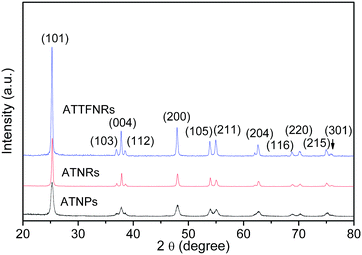
The crystallographic structures of the three prepared products were examined by XRD, as shown in Fig. 1. All diffraction peaks are indexed to (101), (103), (004), (112), (200), (105), (211), (204), (116), (220), (215), and (301) planes of the crystal structure of the anatase TiO2 phase (JCPDS 21-1272), indicating that the products are pure anatase TiO2. The XRD intensity of ATTFNRs is much stronger than that of ATNPs, which is closely related with their shapes. | ||
| Fig. 1 XRD patterns of ATNPs, ATNRs and ATTFNRs. | ||
3.2. Morphology analysis
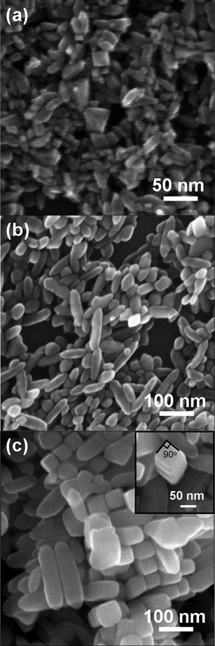
Fig. 2 shows the micrographs of the ATNPs, ATNRs and ATTFNRs obtained by field emission scanning electron microscopy (FESEM). Particle morphology of the products changed dramatically with changing the amount of TBAH. To understand the role of TBAH in morphological evolution of the products, a series of experiments were carried out by introducing different amounts of TBAH. Using 1 mL of TBAH, the product shows three kinds of typical particle morphologies with particle sizes of about 10–45 nm (Fig. 2a). Most of the ATNPs had bi-pyramidal shapes, and the rest had triangular prismatic and rod-like shapes. By increasing the amount of TBAH to 15 mL, the particles mainly consisted of anatase TiO2 nanorods with an average aspect ratio of about 3 (Fig. 2b). With a further increase of the amount of TBAH to 20 mL, the produced sample exhibits a significantly different shape and size (Fig. 2c). The shape of the product was a nanorod with faceted surfaces, a square cross-section (the inset of Fig.2c), and an average aspect ratio of about 4. The ATTFNRs have a proclivity to dense packing with a maximum number of neighbours of four in the equatorial plane. The result shows that TBAH has a great effect on the morphology of the produced TiO2. | ||
| Fig. 2 FESEM images of (a) ATNPs, (b) ATNRs and (c) ATTFNRs obtained with different amounts of TBAH, and the inset is the top view of a single ATTFNR. | ||
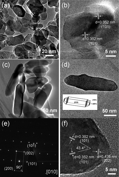
The more detailed structural information of ATNPs and ATTFNRs obtained with different amounts of TBAH were further examined by TEM and selected-area electron diffraction (SAED). Fig. 3 shows two distinct types of nanostructured titania that have been prepared. The overview TEM image (Fig. 3a) of the ATNPs shows that their particles are mostly bi-pyramid-like, with the size ranging from 10 nm to 45 nm. HRTEM image of ATNP is given in Fig.3b, indicating that the lattice fringes with the spacing of 0.35 nm are assigned to (101) planes and the ATNP is originated by oriented attachment of both primary nanocrystals sharing their {101} faces. The rod-like nanoparticles among the ATNPs can be created as a consequence of the oriented-attachment growth mechanism.22 By increasing the amount of TBAH, the tetragonal faceted-rod-like nanoparticles with a size of about 30–60 × 90–250 nm were obtained (Fig. 3c). Fig. 3d shows a TEM image of a representative single ATTFNR with a particle size of about 50 nm in width and 220 nm in length. The corresponding selected-area electron diffraction (SAED) pattern (Fig. 3e) can be indexed by the diffraction from the [010] zone axis, indicating the single-crystal nature of the ATTFNR and preferred growth direction along the c axis.18,20 The interfacial angle between the <001> and <100> direction is 90°, which agrees with the model of ATTFNR enclosed by {010} facets. Fig. 3f shows the two sets of the lattices with an equal fringe spacing of 0.352 nm and an interfacial angle of 43.4°, which agree well with the (101) and (−101) lattice planes of anatase TiO2.18,23 The lattice fringe spacing of 0.476 nm parallel to the top and bottom facets are assigned to (002) planes of anatase TiO2. Based on the HRTEM and SAED analysis, the exposed lateral facets of the ATTFNRs are mainly the {010} facets.
 | ||
| Fig. 3 Representative TEM images of ATNPs and ATTFNRs. (a and c) low-magnification TEM image of ATNPs and ATTFNRs. (b) high-resolution TEM image of single ATNP. (d) low-magnification TEM image, (e) corresponding SAED pattern and (f) high-resolution TEM image recorded from single ATTFNR. Inset of (d): Schematic illustration of the anatase crystal planes of ATTFNR. | ||
3.3. Possible formation mechanism
On the basis of the information gathered from the above XRD analysis, SEM and TEM observations, the possible formation mechanism of the ATTFNRs is deduced for our synthesis. To the best of our knowledge, during the formation of inorganic crystals under equilibrium conditions, crystal habit highly depends on the relative order of surface energies.24 As the primary driving force for crystal growth, the minimization of surface energies leads to different growth rates of various crystal planes with different surface energies, which can control the crystal morphology.25 Crystal planes with high surface energies diminish quickly for the minimization of surfaces energies during a crystal growth process, resulting in a crystal terminated by low-surface-energy facets with a slow growing rate. For anatase TiO2 crystals, the order of the average surface energies is γ{001} (0.90 J m−2) > γ{010} (0.53 J m−2) > γ{101} (0.44 J m−2).26,27 With low amounts of TBAH (1 mL), the formation of an elongated nanocrystalvia oriented attachment occurring in the <101> direction is supported by the TEM micrograph (Fig. 3b). The driving force for such oriented attachment is the reduction of surface energies.28 The TiO2 nanocrystals prepared under low amounts of TBAH are mainly composed of crystals with anatase equilibrium shape, rather than with rod-like shape, according to the Wulff construction29 (Fig. 2a), indicating that the minimization of the overall surface energies is achieved preferentially by Ostwald ripening rather than by oriented attachment. When the amount of TBAH was increased from 1 mL to 15 mL, the prepared particles mainly consisted of anatase TiO2 nanorods, indicating that the minimization of the overall surface energies is achieved preferentially by oriented attachment. Under high TBAH amount (20 mL), Bu4N+ cations and OH− anions play a key role in anatase crystal coarsening, resulting in the tetragonal faceted-rod-like shape with a large percentage of {010} facets (Fig. 2c and 3c). Organic amines selectively adhere to particular crystal facets such as {101}, {010} facets, which can effectively lower the surface energies and slow the growth rate of such facets relative to others.30,31 Although the anatase (101) surface is consistently lowest in energy with a greater fraction of H+ on the surface, O-terminated anatase (010) surface shows a lower surface energy than O-terminated anatase (101) surface.26,29 As a consequence, the preferential adsorption of OH− anions onto (010) surface favors the formation of O-terminated (010) and hence stabilizes the (010) face, resulting in the large percentage of exposed {010} facets.173.4. Photoelectrical and optical properties
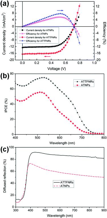
To characterize and compare the electrical properties of the devices based on ATTFNRs and ATNPs photoelectrodes of similar thickness, current density versus voltage (J–V) was measured under AM 1.5G normal illumination (100 mW cm−2, 1 sun) at room temperature, as shown in Fig. 4a. The open circuit voltage (Voc) of the two photoelectrodes is almost similar, 712 and 723 mV for ATTFNRs and ATNPs, respectively. The J–V curves reveal that the DSSC based on the ATTFNRs presents a significantly promoted short circuit current (Jsc), compared to that of the ATNPs. That is, Jsc is increased by 31% from 12.6 mA cm−2 to 16.5 mA cm−2, and concomitantly the fill factor (FF) is increased from 0.62 to 0.66. As a result, the photovoltaic conversion efficiency (η) is enhanced by 37% from 5.65% to 7.73% by using the ATTFNRs. To analyze in more detail the enhanced cell performance, incident monochromatic photo-to-electron conversion efficiency (IPCE) measurements were conducted. Fig. 4b shows the IPCE as a function of wavelength measured at short circuit. The IPCE is determined by the light absorption efficiency of the dye, the quantum yield of electron injection, and the efficiency of collecting the injected electrons at the conducting glass substrate,32 which is strongly affected by the morphology and surface area of the photoelectrode.33 Compared with the ATNPs film, the ATTFNRs film has a higher IPCE from 400 nm to 750 nm wavelength ranges. Generally, the enhanced IPCE in the long wavelength region (600–750 nm) can be attributed to the light scattering effect while the improved IPCE in the short wavelength region (400–600 nm) can be ascribed to high dye adsorption or effective charge transport.7,34 At the maximum value of the IPCE spectra at 520 nm, the IPCE of the film of ATTFNRs is 1.34-fold greater than that of the ATNPs film, which is in good agreement with the ratio of Jsc values. However, we found that the BET surface area of ATTFNRs is 40 m2 g−1, as determined from N2 sorption isotherm at 77 K, which is much less than that of ATNPs (61 m2 g−1). It hints that the great improvement in Jsc and η of ATTFNRs can be due to their large percent of exposed {010} facets which have strong dye adsorption capacity,35 effective charge transport of 1D-structured single crystals and enhanced light scattering effect boosting light harvesting which is confirmed by the diffuse-reflection results (Fig. 4c). Introduction of the ATTFNRs into DSSC reveals ca. 1.3-fold and 1.4-fold improvement in Jsc and η, respectively. While the observed value of Jsc for the ATTFNR-based DSSC (16.5 mA cm−2) still falls short of the highest current value (20.6 mA cm−2) reported for the DSSC based on the mixed anatase TiO2 nanocrystals exposing mainly the (010) plane with high surface areas.19 We believe that balancing surface areas and sizes of ATTFNRs with a large percent of exposed {010} facets will open the possibility to develop high-performance DSSCs. | ||
| Fig. 4 (a) Current density and efficiency as a function of cell voltage and (b) IPCE spectra of the dye-sensitized solar cells based on the ATTFNRs and ATNPs films with similar thickness (about 12 μm). (c) Diffuse-reflectance spectra of the two films of the ATTFNRs and ATNPs with similar thickness (about 12 μm). | ||
4. Conclusion
In summary, we have realized a facile one-pot synthesis of anatase TiO2 tetragonal faceted-nanorods of single crystals with a large percentage of {010} facets via tuning the amount of TBAH. The two roles of the high amount of TBAH as an organic morphology controlling agent are played in the formation of the ATTFNRs: (i) the selective adherement of Bu4N+ cations from TBAH to {010} facets favoring the growth of {010} facets; (ii) meanwhile, the preferential adsorption of OH− anions from TBAH onto {010} surfaces favoring the formation of O-terminated (010) which stabilizes the {010} facets. Dye-sensitized solar cell based on the ATTFNRs exhibits an improved photovoltaic conversion efficiency (7.73%) compared to that of the ATNPs (5.65%), owing to the strong dye adsorption capacity, effective charge transport and enhanced light scattering effect caused by the large percentage of exposed {010} facets, single-crystal 1D-structure and large particle sizes of the ATTFNRs.Acknowledgements
The authors gratefully acknowledge the financial support of the project from the National Science Foundation of China (No. 10775096), China Postdoctoral Science Foundation (No. 20100480579), Key Subject of Shanghai Municipal Education Commission (No. J50102), Special Research Foundation for Training and Selecting Outstanding Young Teachers of Universities in Shanghai, Innovation Foundation of Shanghai University, Nature Science Foundation of Shanghai (No. 06ZR14035) and Shanghai Leading Academic Disciplines (No. T0101).Notes and references
- L. Kavan, M. Gratzel, S. E. Gilbert, C. Klemenz and H. J. Scheel, J. Am. Chem. Soc., 1996, 118, 6716–6723 CrossRef CAS.
- J. S. Chen, Y. L. Tan, C. M. Li, Y. L. Cheah, D. Luan, S. Madhavi, F. Y. C. Boey, L. A. Archer and X. W. Lou, J. Am. Chem. Soc., 2010, 132, 6124–6130 CrossRef CAS.
- A. L. Linsebigler, G. Q. Lu and J. T. Yates, Chem. Rev., 1995, 95, 735–758 CrossRef CAS.
- Y. Mao and S. S. Wong, J. Am. Chem. Soc., 2006, 128, 8217–8226 CrossRef CAS.
- F. Amano, T. Yasumoto, O.-O. Prieto-Mahaney, S. Uchida, T. Shibayama and B. Ohtani, Chem. Commun., 2009, 2311–2313 RSC.
- Z. Zhang, C.-C. Wang, R. Zakaria and J. Y. Ying, J. Phys. Chem. B, 1998, 102, 10871–10878 CrossRef CAS.
- W.-G. Yang, F.-R. Wan, Q.-W. Chen, J.-J. Li and D.-S. Xu, J. Mater. Chem., 2010, 20, 2870–2876 RSC.
- W. Yang, J. Li, Y. Wang, F. Zhu, W. Shi, F. Wan and D. Xu, Chem. Commun., 2011, 47, 1809–1811 RSC.
- Z. A. Peng and X. G. Peng, J. Am. Chem. Soc., 2001, 123, 1389–1395 CrossRef CAS.
- H. G. Yang, C. H. Sun, S. Z. Qiao, J. Zou, G. Liu, S. C. Smith, H. M. Cheng and G. Q. Lu, Nature, 2008, 453, 638–642 CrossRef CAS.
- D. Q. Zhang, G. S. Li, X. F. Yang and J. C. Yu, Chem. Commun., 2009, 4381–4383 RSC.
- X. Han, Q. Kuang, M. Jin, Z. Xie and L. Zheng, J. Am. Chem. Soc., 2009, 131, 3152–3153 CrossRef CAS.
- G. Liu, H. G. Yang, X. Wang, L. Cheng, J. Pan, G. Q. Lu and H. M. Cheng, J. Am. Chem. Soc., 2009, 131, 12868–12869 CrossRef CAS.
- H. G. Yang, G. Liu, S. Z. Qiao, C. H. Sun, Y. G. Jin, S. C. Smith, J. Zou, H. M. Cheng and G. Q. Lu, J. Am. Chem. Soc., 2009, 131, 4078–4083 CrossRef CAS.
- Y. Q. Dai, C. M. Cobley, J. Zeng, Y. M. Sun and Y. N. Xia, Nano Lett., 2009, 9, 2455–2459 CrossRef CAS.
- M. Liu, L. Y. Piao, L. Zhao, S. T. Ju, Z. J. Yan, T. He, C. L. Zhou and W. J. Wang, Chem. Commun., 2010, 46, 1664–1666 RSC.
- G. Liu, J. C. Yu, G. Q. Lu and H. M. Cheng, Chem. Commun., 2011, 47, 6763–6783 RSC.
- B. Wu, C. Guo, N. Zheng, Z. Xie and G. D. Stucky, J. Am. Chem. Soc., 2008, 130, 17563–17567 CrossRef CAS.
- P. Wen, Z. Tao, Y. Ishikawa, H. Itoh and Q. Feng, Appl. Phys. Lett., 2010, 97, 131906-1–131906-3 Search PubMed.
- J. Li and D. Xu, Chem. Commun., 2010, 46, 2301–2303 RSC.
- J. Pan, G. Liu, G. Q. Lu and H. M. Cheng, Angew. Chem., Int. Ed., 2011, 50, 2133–2137 CrossRef CAS.
- J. F. Banfield, S. A. Welch, H. Zhang, T. T. Ebert and R. L. Penn, Science, 2000, 289, 751–754 CrossRef CAS.
- P. Wen, Y. Ishikawa, H. Itoh and Q. Feng, J. Phys. Chem. C, 2009, 113, 20275–20280 CAS.
- J. W. Mullin, Crystallization, Butterworths. London, 1971 Search PubMed.
- D. Yuvaraj, K. Narasimha Rao and K. Barai, Solid State Commun., 2009, 149, 349–351 CrossRef CAS.
- U. Diebold, Surf. Sci. Rep., 2003, 48, 53–229 CrossRef CAS.
- M. Lazzeri, A. Vittadini and A. Selloni, Phys. Rev. B: Condens. Matter, 2002, 65, 119901 CrossRef.
- M. Adachi, Y. Murata, J. Takao, J. Jiu, M. Sakamoto and F. Wang, J. Am. Chem. Soc., 2004, 126, 14943–14949 CrossRef CAS.
- A. S. Barnard and L. A. Curtiss, Nano Lett., 2005, 5, 1261–1266 CrossRef CAS.
- C. M. Liu and S. H. Yang, ACS Nano, 2009, 3, 1025–1031 CrossRef CAS.
- A. Chemseddine and T. Moritz, Eur. J. Inorg. Chem., 1999, 235–245 CrossRef CAS.
- N. G. Park, J. van de Lagemaat and A. J. Frank, J. Phys. Chem. B, 2000, 104, 8989–8994 CrossRef CAS.
- M. K. Nazeeruddin, A. Kay, I. Rodicio, R. Humphry-Baker, E. Mueller, P. Liska, N. Vlachopoulos and M. Grätzel, J. Am. Chem. Soc., 1993, 115, 6382–6390 CrossRef CAS.
- J. Jiu, S. Isoda, F. Wang and M. Adachi, J. Phys. Chem. B, 2006, 110, 2087–2092 CrossRef CAS.
- P. Wen, H. Itoh, W. Tang and Q. Feng, Langmuir, 2007, 23, 11782–11790 CrossRef CAS.
| This journal is © The Royal Society of Chemistry 2012 |
