Controllable fabrication of uniform core–shell structured zeolite@SBA-15 composites†
Xufang
Qian
,
Junming
Du
,
Bin
Li
,
Min
Si
,
Yisu
Yang
,
Yuanyuan
Hu
,
Guoxing
Niu
,
Yahong
Zhang
,
Hualong
Xu
,
Bo
Tu
,
Yi
Tang
and
Dongyuan
Zhao
*
Department of Chemistry, Shanghai Key Laboratory of Molecular Catalysis and Innovative Materials and Laboratory of Advanced Materials, Fudan University, Shanghai, 200433, P. R. China. E-mail: dyzhao@fudan.edu.cn; Fax: +86-21-5163-0205; Tel: +86-21-5163-0205
First published on 28th July 2011
Abstract
Mesoporous core–shell composites with large-pore silica shells are highly desired for a broad spectrum of applications. We report an ultra-dilute liquid-phase coating strategy in an acidic medium for controllable synthesis of uniform micro/mesoporous core–shell composites zeolite@SBA-15 comprising zeolite cores and mesoporous silica SBA-15 shells using triblock compolymer Plunoric P123 as a template. Structural characterizations show that the core–shell composites possess tunable specific surface areas (115–228 m2 g−1), large pores (∼7.0 nm in diameter) with plenty of mesotunnels (∼3.0 nm) from silica shells, original crystalline zeolite frameworks, and opened junctions between micropores and mesopores. The silica shells have ordered 2-D hexagonal mesopore channels, most of which are annularly parallel (fingerprint-like arrangement) to the anisotropic zeolite faces. The shell-thickness is crystal face-dependent, which could be facilely tuned in the range of 30–45 and 40–120 nm on a pinacoids/dome faces and b pinacoids of a zeolite single-crystal, respectively. Moreover, the synthesis parameters such as MgSO4 additive, stirring rate, acidity, temperature and reaction time show great influences on the formation of uniform core–shell composites. Post-hydrothermal treatment at 100 °C has been for the first time adopted to improve mesostructural regularity of the core–shell composites. A scheme regarding surface-induced micellization and hydrothermal rearrangement of mesostructured silica shells in the coating process is proposed to illustrate the formation of core–shell composites. The core–shell composite HZSM-5@SBA-15 (HZ@S15) was employed as a catalyst for methanol to propylene (MTP) conversion, and shows excellent catalytic performance with high methanol conversion (∼98%) and propylene to ethylene (P/E) ratio (∼10.7) as well as propylene selectivity (∼39%).
Introduction
Ordered porous siliceous materials with pore size ranging from micropore (< 2 nm) to mesopore (2–50 nm) according to the IUPAC have been widely investigated for their remarkable applications as catalysts, adsorbents, carriers as well as advanced microelectronics and medical diagnosis.1–6 Therefore, hierarchical pore structures of crystalline zeolite materials fabricated in various ways have attracted much attention during the past decade for their synergetic functions derived from different pore channels.7–14 It is ideally expected that hierarchical pore structure could be a crystalline open framework with stable aluminosilicate compositions similar to the zeolites and ordered multimodal pores, namely the micropores and mesopores are combined together in a zeolite crystalline framework structure.7–9,11–14 On the other hand, among these hierarchical pores, crystalline zeolites with different pore arrangements on the cores and shells have also been of increasing concern for their benefits in catalysis and separation.10,15–17 For examples, core–shell composites β-zeolite@Silicalite-1 and ZSM-5@Silicalite-1 were synthesized and showed remarkable applications in separation, storage, controlled release and catalysis.10,16,17 Furthermore, Yoon and co-workers first synthesized Silicalite-1@mesoporous silica with core–shell structure by using octadecyltrimethoxysilane (C18-TMS) as a template and partial silica source.15 However, the mesopores were not uniform, showing disordered wormlike structure, and the connection of the bimodal pores was not revealed. Therefore, the controlled fabrication of well-defined hierarchical porous core–shell materials with crystalline zeolite cores and ordered mesoporous silica shells is still a great challenge. These micro/microporous and/or micro/mesoporous core–shell composites could be considered as a new type of hierarchical porous materials in terms of distributing different pore structures spatially on the nanoscale.The present coating methods for fabricating mesoporous core–shell materials mainly relied on base-catalyzed sol–gel and self-assembly process of cationic surfactant and silica source.18–27 Quaternary ammonium cationic surfactants such as cetyltrimethylammonium bromide (CTAB) with a positive charged head group were the most widely-used templates for constructing mesoporous core–shell materials, resulting in MCM-41-type silica shell.18,19,23,24,28–33 The limited lengths of alkyl chains of the surfactants lead to small mesopore size (around 2 nm), which greatly restricts the large molecule-involved conversions. Accordingly, large-pore mesoporous core–shell materials synthesized by a facile route is highly desired. However, to the best of our knowledge, amphiphilic triblock copolymers have not been used to fabricate core–shell materials yet.
So far, the compositions served as cores for coating of MCM-41-type silica shells under basic media were primarily noble metal and metal oxide,19,23,25,32 magnetic iron oxide,20,21,24 and rare-earth fluoride,28etc. Most of them lack affinity towards the reactants for mesoporous silica coating. Generally, the core materials were modified with an intermediate such as amorphous silica,20,22,24mercaptopropyl tribethoxysilane,23 and poly(vinylpyrrolidone)19etc. prior to coating. For example, the magnetically responsive microspheres were pre-coated with condensed silica for enhancing the affinity of cores toward organic surfactants and silicate species; hence, the silica interlayer was necessary.24,29 However, for hierarchical porous core–shell structure, the amorphous silicate interlayer may result in poorly opened connections between micropores and mesopores.
Here, we report a versatile ultra-dilute liquid-phase coating strategy for controllable synthesis of uniform core–shell composites comprising zeolite cores and ordered mesoporous silica SBA-15 shells in acidic medium. We choose submicro-sized zeolite single-crystals such as MFI-type Silicalite-1 or ZSM-5 with pseudohexagonal prism-shaped morphologies as core components, triblock copolymer Pluronic P123 as a template to construct mesoporous silica shells under an acidic condition. The core–shell composites possess SBA-15 shell with fingerprint-like channels in parallel to the zeolite surfaces and original crystalline micropore frameworks. The direct connection of zeolite cores and mesoporous silica shells gives rise to a highly opened pore structure. The shell thicknesses are dependent on the crystal faces of zeolite and can be tailored by adjusting the amounts of raw materials.
Core–shell structured zeolite@SBA-15 composites
Core–shell composites with zeolite (Silicalite-1 and HZSM-5) single-crystals as cores and mesoporous silica SBA-15 as shells were synthesized by an ultra-dilute liquid-phase coating strategy (see ESI†). The typical core–shell composites with TEOS/zeolite mass ratios of 0.5, 1.0 and 2.0 were synthesized and named as S@S15-30-40, S@S15-45-100 and S@S15-45-120, respectively, which represent that the core–shell composites consisted of Silicalite-1 (S) cores and SBA-15 (S15) shells with crystal face-dependent shell thicknesses of 30/40, 45/100 and 45/120 nm, respectively. Synthesis parameters such as MgSO4 additive (molar ratios of MgSO4/TEOS = 0, 1, 2), stirring rate (0, 200, 600 and 1200 rpm), reaction temperature (25 and 40 °C), HCl concentration (0.5, 1.0, and 2.0 M) and reaction time (15, 30 and 1440 min) were taken into account in the case of S@S15-45-100. Only one synthesis parameter was changed in each experiment, while keeping the other parameters the same. In addition, the core–shell composite HZSM-5@SBA-15 (HZ@S15) with HZSM-5 (molar ratio of Si/Al = 93) core was synthesized without an MgSO4 additive and employed in methanol to propylene conversion (MTP).Results and discussion
Structure exploration of the core–shell structured composite Silicalite-1@SBA-15
Core–shell composite zeolite@SBA-15 with Silicalite-1 single-crystal as a core and highly ordered mesoporous silica SBA-15 as a shell has been prepared by an ultra-dilute liquid-phase coating strategy in acidic medium. Herein, we take the case of S@S15-45-100 as an example. To elucidate the core–shell structure, we employed high-resolution transmission electron microscope (HRTEM) and field-emission scanning electron microscope (FESEM) techniques for exploring the inner and surface pore structures. TEM images (Fig. 1a) clearly show uniform core–shell particles with silica shells of hexagonally ordered SBA-15-type mesostructures, suggesting that the ultra-dilute liquid-phase coating strategy gives a successful coating on pseudohexagonal prism-shaped Silicalite-1 crystals without separated SBA-15 solids. Furthermore, the shell thicknesses on different faces of a Silicalite-1 single-crystal are obviously different. The crystal faces of a MFI-type single-crystal (inset of Fig. 1a) are identified as dome faces and a, b pinacoids which intersect the a and b axis, respectively. The shell thicknesses with a trapezoidal shape are about 100 nm on b pinacoid of Silicalite-1 single-crystal, while ∼45 nm on both a pinacoid and dome faces (Fig. 1b and c), suggesting the dependence on the crystal faces. The magnified TEM images show highly ordered stripe-like mesopore channels coated on the surfaces of Silicalite-1 (Fig. 1d) and evident crystal phase-dependent shell thicknesses (Fig. 1e). The mesopore channels of silica shells are aligned around the zeolite crystals in parallel. The phenomenon is quite different from the mesoporous core–shell materials with cationic surfactants, wherein MCM-41-type mesoporous silica shells tend to be perpendicular to the particle surface,24,28–30,33 implying the different construction mechanisms of mesostructure. Herein, the anisotropic zeolite crystal faces can be regarded as many micro-substrates for coating of SBA-15; the mesopores align parallel to the zeolite surfaces, consistent with the cases of mesoporous silica films.34–37 The HRTEM image (Fig. 1f) demonstrates that strip-like mesopores adheres to Silicalite-1 micropore frameworks. It is well-established that in the MFI structure, sinusoidal channels in the a-direction of a circular cross section are interconnected with straight channels in the b-direction of an elliptical cross section and a tortuous path is present along the c-direction. However, in the present case, the mesopores align parallel to different zeolite crystal faces in a-, b- and c-directions, therefore, the junction between micropores and mesopores is a decisive factor in communication within the core–shell frameworks. The junction of the composite structure can be regarded as the interface of mesoporous silica and Silicalite-1 (micro-substrates) in terms of opened pores probably supported by amorphous silica species. It implies that the triblock copolymers are preferentially attached on the Silicalite-1 surfaces with high positive charges (ξ-potential: 42 mV at pH around 2) during the coating process under the strong acidic condition. The cross-linkage of Si–OH groups on Silicalite-1 surfaces and SBA-15 walls inevitably occurs upon heat treatment, resulting in the presence of amorphous silica within the porous junction, which can not only enhance the adhesive strength, but also facilitate the communications of guest molecules inside the core–shell structure.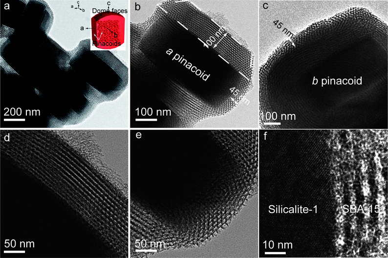 | ||
| Fig. 1 TEM images of S@S15-45-100 with crystal face-dependent shell thicknesses of ∼45/100 nm after one-step calcination at 550 °C in air for 5 h: uniform core–shell particles without separated SBA-15 (a); a core–shell particle with shell thicknesses of ∼100 nm on b pinacoid and ∼45 nm on dome face, respectively (b); a core–shell particle with shell thickness of ∼45 nm on a pinacoid (c); strip-like mesochannels (d) and overlaps of strip-like and hexagonal mesopores (e) closely connected with Silicalite-1 and cross-section HRTEM image of the core–shell composite indicating the highly opened junction between micropores and mesopores (f). Inset in (a) is the geometric model of Silicalite-1 single-crystal. | ||
SEM images show that pristine Silicalite-1 single-crystals are highly dispersed and of pseudohexagonally prismatic shape (Fig. 2a). After the coating process with a mass ratio of TEOS/zeolite = 1.0, uniform core–shell particles are obtained (Fig. 2b and 2c), indicating an honest coating process. The surface structure of a core–shell particle (Fig. 2d) clearly shows annularly tubular mesochannels with a fingerprint-like pattern and a local terrace morphology (corresponding to the trapezoidal shape in TEM images) on b pinacoid of Silicalite-1 crystal as well as ordered strip-like mesopore channels on adjacent a pinacoid and dome face, which indicates that all of the pore channels are parallel to the respective crystal faces in agreement with the TEM results. High-resolution FESEM (HRFESEM) image (Fig. 2e) also demonstrates highly ordered mesostructures with spiral arrangements. In addition, some defective domains with interstices are observed at the connection of local shells on adjacent crystal faces, which are probably caused by the mismatched coalescence of mesoporous silica shells on different crystal faces. This phenomenon implies that the coating of silica shells progresses independently on the anisotropic crystal faces. Plenty of mesotunnels (∼3 nm in diameter) (white arrows in Fig. 2e) are observed in the silica walls, which render the 2-D frameworks of SBA-15 shells with better connectivity in three dimensions. The defective domains as well as the mesotunnels probably facilitate mass diffusion and effective communications between the micropores and mesopores. In addition, we can roughly measure the thickness of the local terrace structure (∼100 nm) located on b pinacoid by FESEM image (Fig. 2e), which is in agreement with the value (∼100 nm) obtained by TEM image (Fig. 1b). Based on the EM results, we conclude that the core–shell composite S@S15-45-100 possesses crystal face-dependent shell thicknesses (45/100 nm), ordered mesochannels in parallel to Silicalite-1 surfaces with abundant mesotunnels in silica walls and original crystalline micropore frameworks.
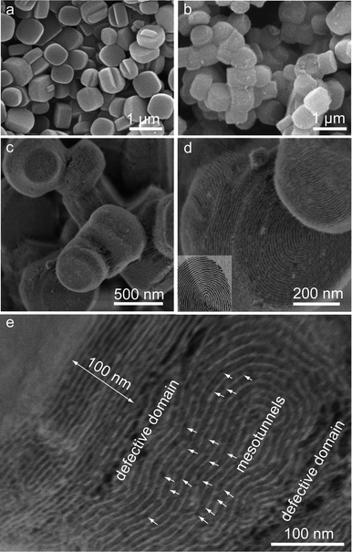 | ||
| Fig. 2 SEM images of pristine Silicalite-1 crystals and calcined S@S15-45-100: highly dispersed pristine Silicalite-1 single-crystal particles (a); uniform core–shell particles without SBA-15 by-products (b) and (c); the surface structure of a core–shell particle indicating fingerprint-like mesopore channels regularly arranged on Silicalite-1 single-crystals in parallel (d); HRSEM image of a local domain for a core–shell particle showing the defective connections of shells on adjacent crystal faces and plenty of mesotunnels located in silica walls (e). Inset in (d) is a picture of a fingerprint. | ||
Pure SBA-15 was also synthesized by the ultra-dilute liquid-phase strategy. Small-angle X-ray scattering (SAXS) patterns of as-made SBA-15 (Fig. 3A(a)) and S@S15-45-100 (Fig. 3A(b)) show one resolved and two weak scattering peaks that can be indexed to the 10, 11, 20 planes of a 2-D hexagonal mesostructure with p6mm symmetry, clearly indicating that the ordered mesostructured silica can be formed in homogeneous and heterogeneous systems, respectively. After calcination at 550 °C for 5 h in air, the scattering peaks of S@S15-45-100 (Fig. 3B(b)) are more resolved than that of pure SBA-15 (Fig. 3B(a)), suggesting the mesostructure with high thermal stability.
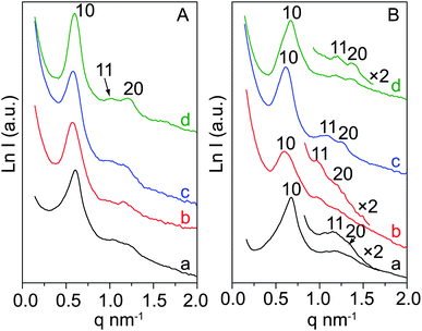 | ||
| Fig. 3 SAXS patterns of as-made (A) and calcined (B) mesoporous silica SBA-15 and the core–shell composites with different shell thicknesses: SBA-15 (a); S@S15-45-100 (b); S@S15-30-40 (c) and S@S15-45-120 (d). | ||
Wide-angle X-ray diffraction (XRD) pattern of the pristine Silicalite-1 single-crystals displays characteristic diffraction peaks of MFI structure (Fig. S1a†). S@S15-45-100 shows the same diffraction peaks with slightly decreased intensities (Fig. S1b†), suggesting that the crystalline zeolite framework is well-retained during the coating process and the weak shield effect of SBA-15 shells to X-rays.
N2 sorption isotherms of pristine Silicalite-1 particles show a typical type-I curve with a sharp uptake at the low relative pressure (P/P0), indicating the characteristic micropore (Fig. 4A(a)). Whereas, S@S15-45-100 with shell thicknesses of 45/100 nm (Fig. 4A(b)) shows a retained uptake at the low P/P0 (type-I curves) and typical type-IV curves with a capillary condensation step at P/P0 = 0.65–0.80 as well as H1-type hysteresis loop, indicating the combinative sorption behavior of micropores and mesopores. The pore size distribution (PSD) is calculated by the non-local density functional theory (NLDFT) method reflecting the pore sizes from micropore to mesopore.38 Pristine Silicalite-1 displays a very sharp PSD centered at 0.86 nm from 10-membered-rings and the other broad one with a mean value of 3.6 nm due to the aggregation of zeolite crystals (Fig. 4B(a)). The PSD curve (Fig. 4B(b)) of S@S15-45-100 demonstrates the original micropore diameter at 0.86 nm and sharp bimodal-pores with uniform sizes of 3.4 and 7.0 nm in the mesopore range corresponding to mesotunnels located in the walls and cylinder-shaped large mesopores, respectively, in good consistency with the HRFESEM results. The specific BET surface area and total pore volume of Silicalite-1 are 375 m2 g−1 and 0.26 cm3 g−1 (Table 1), respectively, with less contributing from external surfaces (71 m2 g−1, 19% and 0.09 cm3 g−1, 35%). After coating with SBA-15, the porosity of S@S15-45-100 from the mesopores increases evidently. The specific BET surface area and total pore volume increase to 414 m2 g−1 and 0.45 cm3 g−1, respectively, whereas 140 m2 g−1 (34%) and 0.31 cm3 g−1 (69%) stem from external surfaces (i.e.SBA-15) (Table 1), suggesting the accessible micro/mesoporous core–shell structures.
| Sample | a 0 (nm) | S BET (m2 g−1) | S micro (m2 g−1) | S ex (m2 g−1) | V micro (cm3 g−1) | V T (cm3 g−1) | D micro (nm) | D meso (nm) |
|---|---|---|---|---|---|---|---|---|
| Silicalite-1 | — | 375 | 304 | 71 | 0.17 | 0.26 | 0.86 | 3.6 |
| S@S15-30-40 | 12.2 | 387 | 272 | 115 | 0.15 | 0.34 | 0.86 | 2.9/8.1 |
| S@S15-45-100 | 11.8 | 414 | 274 | 140 | 0.14 | 0.45 | 0.86 | 3.5/7.0 |
| S@S15-45-120 | 10.8 | 467 | 239 | 228 | 0.13 | 0.49 | 0.86 | 3.6/6.9 |
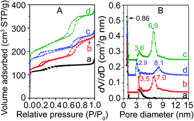 | ||
| Fig. 4 N2 sorption isotherms (A) and pore size distribution curves (B) of pristine Silicalite-1 and the core–shell composites with different shell thicknesses after being calcined at 550 °C for 5 h in air: (a), pristine Silicalite-1; (b), core–shell composites S@S15-45-100; (c), S@S15-30-40 and (d), S@S15-45-120, respectively. The isotherms for samples (b), (c), and (d) were offset vertically by 25, 65 and 75 cm2 g−1. The pore size distributions for samples (b), (c), and (d) were offset vertically by 0.04, 0.15 and 0.25 cm3 g−1. | ||
The benzene sorption isotherm of pristine Silicalite-1 (Fig. 5a) shows a steep uptake at a low P/P0 and a slight increase tendency derived from the voids of aggregated particles when raising the adsorption pressure, indicating the predominant micropores. For S@S15-45-100, a more obviously enhanced adsorption phenomenon appears even over the range of tested P/P0 (> 0.9) in addition to a retained sharp uptake step at the low P/P0 (Fig. 5b), implying the remarkable micro/mesopore properties. The adsorption amount on S@S15-45-100 (1.6 mmol g−1) has an increase of about 23% compared with that of pristine Silicalite-1 (1.3 mmol g−1) due to the contribution of mesoporous silica shells. These results are in coincidence with the N2 sorption data. Based on the kinetic curves (the inset of Fig. 5) of diffusion process for rigid benzene molecules, the calculated diffusion coefficient D for S@S15-45-100 (D = 1.39 × 10⁻¹⁶ m2s−1) is evidently larger than that for pristine Silicalite-1 (D = 9.22 × 10⁻¹⁷ m2s−1). The result indicates the enhanced diffusion of benzene molecules in the core–shell composite structures probably due to the improved surface toughness due to the mesoporous shells, which is of benefit to the sorption of benzenes.39 It also confirms the highly opened pore connections between the core and shell.
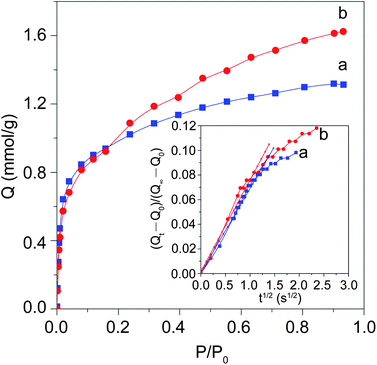 | ||
| Fig. 5 Gravimetric adsorption isotherms of benzene on the calcined pristine Silicalite-1 (a) and the core–shell composite S@S15-45-100 (b). The inset demonstrates the kinetic curves of short-time diffusion progresses for the two samples. | ||
FT-IR spectrum of as-made S@S15-45-100 (Fig. S2†) shows the bands at ∼2800 and 1100 cm−1 assigned to the C–H stretching vibrations of the organic templates (i.e. P123 and TPA+) and the overlap of C–O and Si–O–Si vibration, respectively.40 The disappearance of bands at 2800 cm−1 for calcined S@S15-45-100 indicates a complete elimination of P123 and TPA+ after on-step calcination at 550 °C in air. The Si–OH vibrations at 972 cm−1 become weaker for the calcined S@S15-45-100 compared with the as-made one, indicating the high condensation degree of silanol groups upon heat treatment. The vibration band at 550 cm−1 and a strong one at 450 cm−1 for all the samples are assigned to the asymmetric stretching mode of five-ring in the MFI framework and the Si–O bending mode,41 respectively.
Effects of synthesis parameters
The shell thicknesses of SBA-15 can be tailored in the range of 30–45 nm on a pinacoids/dome faces and 40–120 nm on b pinacoids, respectively, by tuning the mass ratios of TEOS/zeolite in the range of 0.5–2. When the mass ratio of TEOS/zeolite is 0.5, the uniform core–shell particles with ordered mesoporous silica shells are obtained (Fig. 6a), suggesting the facile and reproducible liquid-phase coating strategy. Notably, the magnified TEM image (Fig. 6b) shows the crystal face-dependence shell-thicknesses for a single core–shell particle in terms of ∼40 nm on b pinacoid and ∼30 nm on dome face, respectively. Moreover, the mesoporous silica shells of S@S15-30-40 are highly ordered and of characteristic strip-like and hexagonal mesopores (Fig. 6c and d). When the mass ratio of TEOS/zeolite increases to 2, the same phenomena, including crystal face-dependent shell thicknesses of 45/120 nm and ordered SBA-15-type mesostructures (Fig. 6e and f), are observed in the core–shell composite S@S15-45-120. Apparently, the shell thicknesses preferentially thicken on the b pinacoids of a Silicalite-1 crystal (40–120 nm), and maintain a nearly constant value (30–45 nm) on the other adjacent crystal-faces in order to minimize the surface energy of the core–shell composites to some extent.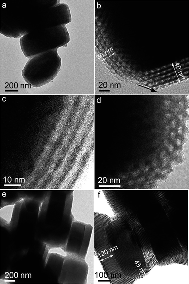 | ||
| Fig. 6 TEM images of S@S15-30-40 (a–d) and S@S15-45-120 (e, f) after being calcined at 550 °C for 5 h in air: the uniform core–shell composite with mass ratio of TEOS/zeolite = 0.5 (a); crystal face-dependent shell thicknesses of ∼30/40 nm (b); ordered strip-like (c) and hexagonal mesochannels (d); core–shell particles with shell thicknesses of ∼45/120 nm (e, f). | ||
After coating with SBA-15, the core–shell composites with tailored shell thicknesses (Fig. S3†) become somewhat aggregated and have pseudohexagonally prismatic morphologies with obtuse angularity. However, when the mass ratio of TEOS/zeolite increases to 2, a small quantity of particle-like by-products (red arrows in Fig. S3b†) are observed in S@S15-45-120, indicating Silicalite-1 particles can not offer sufficient interface for nucleation and growth of mesoporous silica. These phenomena indicate the crucial role of the heterogeneous zeolite surfaces for construction of SBA-15 shells in acidic medium.
SAXS patterns (Fig. 3b–c) of the as-made and calcined core–shell composites with different shell thicknesses reflect the ordered hexagonal mesostructures, which is coincident with the TEM results. The mesostructural regularity is gradually improved with the increased shell thicknesses from 30/40, 45/100 to 45/120 nm. Moreover, as the shell thickness increases, the scattering peaks (Fig. 3B(b–c)) shift evidently to higher q values, indicating the decrease of unit cell parameters a0 (Table 1). The calculated mesostructural shrinkages upon calcination for the core–shell composites with increased shell thicknesses from 30/40, 45/100 to 45/120 nm and pure SBA-15 are 4.1, 4.8 10.0 and 10.2%, respectively. Therefore, the enlarged shrinkage of S@S15-45-120 with shell thicknesses of 45/120 nm probably comes from the separated SBA-15 particles. This phenomenon provides evidence that the strong bonding effect from the cross-linkage of Si–OH groups of zeolite surfaces and SBA-15 shells results in the small framework shrinkage.
N2 sorption isotherms (Fig. 4A(b–c)) of these core–shell composites with increased shell thicknesses exhibit similar combinative type-I and type-IV curves, but more obvious hysteresis loops due to the increased amounts of mesoporous silica in agreement with SAXS results. The corresponding PSDs (Fig. 4B(b–c)) show the original ordered micropores (0.86 nm) regardless of the shell thicknesses, and characteristic bimodal-pores ranging from 2.9–3.6 nm and 8.1–6.9 nm assigned to mesotunnels and cylinder-shaped large mesopores, respectively. The BET surface areas and total pore volumes (Table 1) undergo a progressive increase due to the enhanced proportions of mesoporous silica. In addition, the decreased microporosity (Table 1) is caused by the reduced zeolite contents.
The formation of SBA-15 shells on heterogeneous zeolite single-crystals is more rigorous relative to the self-assembly process in a homogeneous phase. To understand the formation of the core–shell composites by the ultra-dilute liquid-phase coating strategy, different synthesis parameters such as MgSO4 additive, stirring rate, HCl concentration, temperature and reaction time were also investigated.
Without the addition of MgSO4, the resulting core–shell composite (Fig. S4a†) shows uniform and sticky particles with irregularly rounded block-like morphologies, and a large proportion of core–shell particles are covered with “doughnut-like hats”. These results are different with that of S@S15-45-100 (Fig. 2b) synthesized under the same condition but adding a large amount of MgSO4 (molar ratio MgSO4/TEOS= 2). In addition, a relatively small amount of MgSO4 (MgSO4/TEOS = 1) cannot inhibit the formation of “doughnut-like hats” on zeolite particles (Fig. S4b†). FESEM images of the core–shell composite without MgSO4 additive confirm the irregularly rounded block-like (Fig. 7a) morphologies with rough surfaces (Fig. 7b). The “doughnut-like hats” in SEM images are in the form of annular-arranged mesopores defectively constructed on b pinacoid of a Silicalite-1 single-crystal (Fig. 7c), and thereby the connection of silica shells on adjacent crystal faces is ambiguous. Many defective domains on both micro- and mesoscales including the “doughnut-like hats” and random-attached SBA-15 rods (microscale) as well as disordered mesochannels (mesoscale) (Fig. 7d) lead to the rough surfaces and loss of the zeolite original morphologies. These phenomena suggest that MgSO4 additive facilitates the regular coating of mesostructured silica in acidic medium due to the enhanced interactions of inorganic and organic species.42,43 The presence of well-resolved scattering peaks (Fig. S5A†) and combined type-I and type-IV isotherms (Fig. S5B†) suggest the formation of ordered mesostructure primarily from the “doughnut-like hats” and random-attached SBA-15 rods.
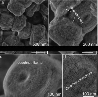 | ||
| Fig. 7 FESEM images of the calcined core–shell composite synthesized without MgSO4 additive: irregular block-like core–shell particles with rough surfaces (a); separated SBA-15 rods randomly attached on core–shell particles resulting in rough surfaces (b); “doughnut-like hat” with annularly arranged mesopore channels (c); HRFESEM image (d), showing the defective mesopores, which suggests the irregular coating process without MgSO4 additive. | ||
Three additional stirring rates (0, 200 and 1200 rpm) were taken into account in material synthesis. SAXS patterns (Fig. S6a–c†) of the obtained products show ordered hexagonal mesopore structure, indicating the negligible effect on structural regularity. However, SEM images show obvious phase separation of SBA-15 for the above samples obtained at relatively low (0 and 200 rpm) (Fig. S7a and b†) or high stirring rates (1200 rpm) (Fig. S7c†). It suggests the honest coating of SBA-15 on an individual zeolite particle is affected by the shearing flow at different stirring rates. HRFESEM images of the product obtained at a quiescent condition (0 rpm) show obvious annular mesochannels with fingerprint-like patterns in ∼half of a unit-cell thickness (Fig. S8a–c†). On the other hand, the independent coating of mesoporous silica shells on different crystal faces is observed in Fig. S8d†, where the confluent growth of the silica shells has not occurred yet.
With regard to the influence of acidity, the intensity of the SAXS peaks decreases as lowering the HCl concentrations from 2.0 (Fig. 3B(b)), 1.0 to 0.5 M (Fig. S6d and e†), indicating the reduced mesostructured periodicity. When it decreases to 0.5 M, the mesostructure ordering becomes poor. The core–shell composites with relatively low HCl concentrations also show some separated SBA-15 aggregates and particles (Fig. S7d and e†), suggesting that the strong acidity is preferred in our present synthesis.
Moreover, conventional reaction temperature (40 °C) for SBA-15 synthesis is not suitable in the coating process. Although the SAXS profile of the product displays well-resolved scattering peaks (Fig. S6f†), many SBA-15 rods separately grow beyond the surfaces of zeolite particles (Fig. S7f†), indicating that low reaction temperature is a prior choice in the coating strategy with triblock copolymer as a template.
To explore the structural evolutions of SBA-15 on zeolite single-crystals during the coating process, specimens served to HRFESEM measurements were collected at different times after adding the silica source and quenched at liquid nitrogen temperature. At the initial stage (15 min after TEOS was added), a rough core–shell particle with a distinct coating layer is observed, while spherical pores are randomly distributed in the amorphous silica layer (Fig. 8a). After half an hour, some domains with short-range cylinder mesopores (Fig. 8b) appear, indicating the transformation from spherical to cylinder micelles during the coating process.44,45 Well-ordered fingerprint-like and strip-like SBA-15 mesostructures (Fig. 8c, d) are observed after a long time (1440 min), indicating that the amorphous silica shell undergoes the transformation from a disordered intermediate silicate coating-layer to an ordered mesotructured silica shell. Moreover, a large amount of small particles can be observed on the particle surface (Fig. 8c,d), suggesting that the coating process has not been completed yet. These amorphous silica particles disappear after the hydrothermal treatment at 100 °C for 24 h, resulting in smooth and clear mesopore channels (Fig. 2c–e). It suggests the further rearrangement of the mesostructure during the hydrothermal treatment.
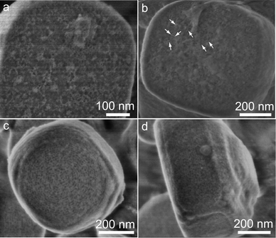 | ||
| Fig. 8 Mesostructure evolutions of SBA-15 shells on zeolite single-crystal particles after addition of silica source TEOS in the case of S@S15-45-100: disordered mesostructured silicate coating with randomly distributed spherical pores after 15 min (a); appearance of short-range cylinder pores after 30 min (b), indicating the continuous arrangement of mesostructured silicate on zeolite particles; ordered 2-D hexagonal mesostructures with a plenty of small particles after 1440 min (c, d). | ||
Understanding the coating process
The key point of the ultra-dilute liquid-phase coating strategy by using Plunoric P123 as a template in acidic medium for the synthesis of uniform core–shell zeolite@mesoporous silica composites is the preferential aggregation of surfactants on zeolite surfaces. A scheme regarding surface-induced micellization and rearrangement of mesostructured silica shells for the coating process is proposed (Scheme 1).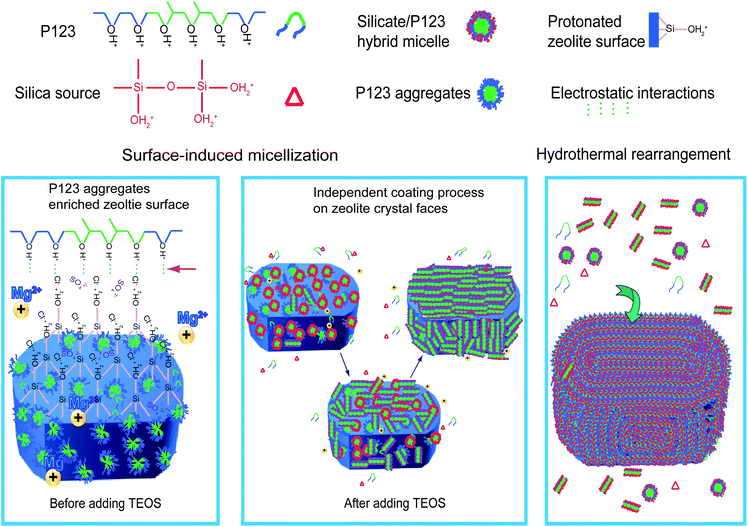 | ||
| Scheme 1 Construction process of the mesostructured silica SBA-15 on a zeolite single-crystal by an ultra-dilute liquid-phase coating strategy in acidic medium. | ||
Zeolite single-crystals as the perfect crystalline microporous silicates still contain many Si–OH groups on their surfaces, which could be protonated in a strong acidic medium, resulting in highly positive charged surfaces (42 mV at pH around 2 for Silicalite-1). It is well-known that the triblock copolymer with PEO/PPO blocks can also be protonated (PEOH+/PPO) in a strong acidic medium.46,47 Prior to the addition of silica source, protonated triblock copolymers are preferentially attached on the surface of zeolite crystals with plenty of protonated Si–OH (H+HO–Si) via electrostatic interactions with counter ions, such as Cl− and SO42−, thus locally enriched at the zeolite surfaces. On the other hand, an ultra-dilute surfactant solution (0.19 wt%) is required to reduce the concentration in the homogeneous phase and inhibit the separated nucleation and growth of mesostructured silicate in the solution. Accordingly, the gradient of surfactant concentration is resulted in the coating system.
Zeolite particle with enriched P123 aggregates as a core has anisotropic crystal faces that serve as micro-substrates for the coating of mesostructured silicates. After the addition of silica source, the silicate oligomers from acid-catalyzed hydrolysis of TEOS begin to interact with Pluronic P123 aggregates on zeolite-crystal surfaces to form silicate/P123 micelles. The positively hydrolyzed silica species H+HO–Si tend to interact with hydrophilic PEOH+ blocks via counter ions and form silica frameworks around the PEOH+ segments, resulting in the connecting mesotunnels between large mesopores. The enhanced interaction of inorganic–organic components is responsible for the ordered large mesopores and also connecting mesotunnels. Continued hydrolysis and condensation of silicate species promote the coating process of these silicate/P123 micelles on zeolite particles, which assemble a uniform silicate coating layer with disordered mesostructure at the solid/liquid interface. At this stage, the coating process proceeds independently on different anisotropic zeolite faces. To minimize the surface energy of the core–shell composite, the shell construction occurs on the b pinacoids to give rise to the crystal-dependent shell thickness. During the process, the spherical silicate/P123 micelles at the interface begin to arrange into short-range cylinder-like silicate/P123 micelles. After a successive reorganization, the disordered shell structure envolves into an ordered 2-D hexagonal mesostructure with defective domains. At this period, annular arranged mesopore channels with fingerprint-like pattern in parallel with the crystal faces are preferred, which could effectively minimize the interfacial tension.37 The residual nutrients including Pluronic P123, silicate oligomer species and even small silicate/P123 nanocomposites participate in the hydrothermal rearrangement (100 °C for 24 h) to remedy the defective domains and mesostructures.
In the coating process, the enhanced interactions of reactive species assisted by MgSO4 facilitate the regular alignment of silicate/P123 micelles toward an ordered mesostructures on the zeolite surfaces. In addition, the stirring rates affect the movements of the zeolite crystals as well as the shearing flow in the solution. From the viewpoint of force analysis, a positive charged zeolite crystal in a certain shearing flow and gravity field has complex forces correlating with each other at different stirring rates. A mild stirring rate and relatively low temperature provide a coating environment with proper kinetics and thermodynamics, which assists the honest nucleation and growth of mesostructured silicate on zeolite surfaces. On the other hand, the hydrolysis and polymerization rates of silicate oligomers are proportional to [H+] below pH = 2,48 the high [H+] concentration benefits to control the coating process over the zeolite particles without self-aggregation of reactive species. Based on the understanding of the coating process, uniform core–shell composite (HZ@S15) with Al-incorporated HZSM-5 cores (Fig. S9†) were obtained without MgSO4 by the general ultra-dilute liquid-phase coating strategy and employed in MTP catalytic reaction.
MTP catalytic performance
The conversion of methanol to propylene (MTP) and olefins over ZSM-5 has become a remarkable alternative technique instead of the petroleum route.49–52 The previous efforts for MTP conversion mainly focused on the intrinsic properties of ZSM-5 including acidity,49pore strucuture51,52 and framework modification.52 In addition, the binder and inert materials such as alumina with disordered mesopores have been served as additives in zeolite catalysts for promoting the methanol to olefin conversion due to their improved accessibility for the reactants and anti-coking ability.53In this study, the uniform core–shell composite catalyst HZ@S15 with ∼70 wt% of HZSM-5 (Si/Al = 93) and ∼30 wt% of mesoporous silica (measured by ICP) (Fig. S9†) were employed in MTP conversion. The textural properties of HZ@S15 demonstrate increased mesopore specific surface areas from SBA-15 shells and about 23% loss of micropore surface area compared with that of pristine HZSM-5 (data not shown here). With regard to the acidity, NH3-TPD profiles of pristine HZSM-5, mechanical mixture containing 70 wt% of HZSM-5 and 30 wt% of SBA-15 (denoted as HZSM-5&S15) and HZ@S15 (Fig. S10A†) have two peaks at ∼160 and ∼320 °C, corresponding to the weak and strong acidic sites, respectively. Note that the desorption temperatures of NH3 on strong acidic sites (the latter peak) for the three samples undergo a gradual decrease from 338 (HZSM-5), 323 (HZSM-5&S15) to 318 °C (HZ@S15), indicating a little decrease of the surface acidity derived from the shell decoration. Moreover, the characteristic bands at 1455 and 1545 cm−1 can be observed in the FTIR spectra of pyridine adsorption for the three samples, assigned to the Lewis and Brønsted acid sites, and the band at 1445 cm−1 (Fig. S10b†) is from the hydrogen bonded pyridine. The intensity of the band at 1545 cm−1 (Brønsted acid sites) is slightly reduced according to the order HZSM-5 > HZSM-5&S15 > HZ@S15 in agreement with the NH3-TPD results. The loss of micropore surface areas and total acidity (∼33%) (Table S1†) for the core–shell composite catalyst HZ@S15 are mainly caused by the decreased proportion of HZSM-5 component in the core–shell catalyst HZ@S15 (∼70 wt% of HZSM-5) relative to pristine HZSM-5 (100 wt%). These phenomena indicate that the crystalline microporous properties of HZSM-5 are retained after coating with SBA-15 shells. The core–shell catalyst HZ@S15 shows a high methanol conversion (∼98%) and propylene selectivity (above 39%) after 50 h, which keeps stable in the overall duration of 200 h (Fig. 9). The propylene to ethylene ratio (P/E ratio) gradually increases and the average value within 200 h is 10.7 (Table S1†). At the initial 25 h, the selectivity of C4= and C5= olefins, C5 saturated hydrocarbons increases obviously, whereas C1–C4 saturated hydrocarbons and aromatics decrease evidently (Fig. S11C†). Afterwards, the reaction reaches a relatively steady state. The C6+ (i.e., including C6 and higher non-aromatics) non-aromatic hydrocarbons undergo a slight decrease initially and fluctuant increase subsequently.
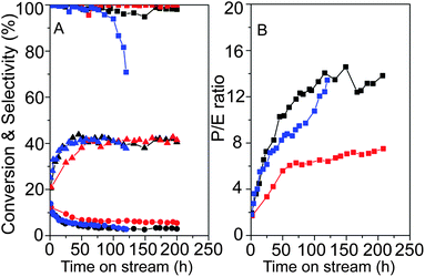 | ||
| Fig. 9 Time on stream performances of pristine HZSM-5 (red color), the mechanical mixture HZSM-5&S15 with 70 wt% of HZSM-5 and 30 wt% of SBA-15 (blue color) and HZ@S15 (black color): methanol conversion (■), selectivity of ethylene (●) and propylene (▲) (A); the ratio of propylene to ethylene (P/E ratio) (B). | ||
For comparison, pristine HZSM-5 catalyst (Si/Al = 93) and mechanical mixture HZSM-5&S15 were also involved in the MTP reaction. The methanol conversion and propylene selectivity for the pristine HZSM-5 and the core–shell composite HZ@S15 are similar across the overall 200 h, whereas, the mechanical mixture HZSM-5&S15 shows obvious inferiority with an evident decrease in catalytic activity at ∼100 h (Fig. 9). The relatively higher selectivity of ethylene for pristine HZSM-5 results in less increase in P/E ratio (average value of ∼6.1) compared with HZ@S15 and mechanical mixture HZSM-5&S15 (Fig. 9 and Table S1†). Based on the comparative results of MTP conversion (Fig. 9, Fig. S11† and Table S1†), several conclusions are summarized as following: 1) HZSM-5 is the active component for methanol to olefin reaction which mainly contributes to the high methanol conversion even for the core–shell catalyst with ∼70 wt% of zeolite; 2) the higher average P/E ratio (Table S1†) for the core–shell composite catalyst is related to the lower ethylene selectivity on the premise of similar propylene selectivity (∼39%) compared with pristine HZSM-5; 3) the core–shell composite catalyst shows obvious superiority for obtaining relatively larger hydrocarbons (i.e., C5+) and reduced selectivity for C1–C4 saturated hydrocarbons.
After decoration with SBA-15 shells, partial surface acidity of the zeolite core inevitably sacrifices, which leads to the lower selectivity of ethylene compared with pristine HZSM-5. Therefore, the P/E ratio for the core–shell catalyst is higher than that of pristine HZSM-5. On the other hand, the mesoporous silica shells with high surface areas and large pore channels can provide sufficient voids for capturing reactant molecules and also promote molecule diffusion, which gives a high methanol conversion and propylene selectivity, even though the content of active HZSM-5 (∼70 wt%) is less than pristine HZSM-5 (100 wt%) for the core–shell catalyst. The core–shell composite catalyst shows obvious superiority in catalytic activity compared with that of the mechanical mixture, which further reflects the importance of the direct connected and highly opened junctions between HZSM-5 cores and SBA-15 shells in the catalytic process. Moreover, the direct connection could prevent dealumination of zeolite in the rigorous vapor atmosphere, and the large mesopores favor the conversion of light olefins into C5–C6hydrocarbons that are highly demanded in petroleum refining industry. The deep catalytic properties and extended catalytic applications of these core–shell composite catalysts are still under investigation.
Conclusions
Uniform core–shell structured zeolite@SBA-15 composites are first synthesized by using amphiphilic triblock copolymer Pluronic P123 as a template via an ultra-dilute liquid-phase coating strategy in acidic medium. The micro/mesoporous core–shell structure consists of intrinsically crystalline microporous frameworks and highly ordered SBA-15 mesopores (6.9–8.1 nm) with plenty of mesotunnels (2.9–3.6 nm) located in amorphous silica walls. In the core–shell structure, zeolite cores directly connect with the large mesopores of SBA-15 resulting in a highly opened junction between micropore and mesopore frameworks. The unique crystal face-dependent shell-thicknesses can be tailored to some extent (30–45/40–120 nm), which results in the tunable porosity. The surface-induced micellization deduces the self-assembly and honest coating of mesostructured silicates on the surfaces of zeolite single-crystal particles to form uniform core–shell composites. This ultra-dilute liquid-phase coating method is facile, reproducible and also suitable for different zeolite materials to construct the hierarchical core–shell structures. HZ@S15 catalysts with ∼70 wt% of active zeolite content show excellent catalytic performance with high conversion (∼98%) and propylene selectivity (∼39%) in MTP reaction. The mesoporous silica shells can provide large spaces for capturing methanol and sacrifice partial surface acidity, which yields a higher P/E ratio (∼10.7) and selectivity of C5–C6hydrocarbons relative to pristine HZSM-5 catalyst and the mechanical mixture.Acknowledgements
We thank Dr Q. S. Wu, Y. Chen, L. Y. Wang, H. Cao, X. D. Yang and D. Feng for characterization assistance. This work was supported by the NSF of China (20641001, 20890123, 20721063, and 20821140537), the Agilent Technologies Foundation (0214), the State Key Basic Research Program of the PRC (2006CB932302, 2009AA033701), National Basic Research Priorities Program (2007-CB914100/3) and Shanghai Leading Academic Discipline Project (B108).Notes and references
- A. Corma, Chem. Rev., 1997, 97, 2373–2419 CrossRef CAS.
- F. Schüth and W. Schmidt, Adv. Mater., 2002, 14, 629–638 CrossRef.
- M. E. Davis, Nature, 2002, 417, 813–821 CrossRef CAS.
- Y. Wan and D. Y. Zhao, Chem. Rev., 2007, 107, 2821–2860 CrossRef CAS.
- A. Vinu, V. Murugesan, W. Bohlmann and M. Hartmann, J. Phys. Chem. B, 2004, 108, 11496–11505 CrossRef CAS.
- A. Vinu, J. Justus, C. Anand, D. P. Sawant, K. Ariga, T. Mori, P. Srinivasu, V. V. Balasubramanian, S. Velmathi and S. Alam, Microporous Mesoporous Mater., 2008, 116, 108–115 CrossRef CAS.
- C. J. H. Jacobsen, C. Madsen, J. Houzvicka, I. Schmidt and A. Carlsson, J. Am. Chem. Soc., 2000, 122, 7116–7117 CrossRef CAS.
- Y. S. Tao, H. Kanoh and K. Kaneko, J. Phys. Chem. B, 2003, 107, 10974–10976 CrossRef CAS.
- S. S. Kim, J. Shah and T. J. Pinnavaia, Chem. Mater., 2003, 15, 1664–1668 CrossRef CAS.
- Y. Bouizi, I. Diaz, L. Rouleau and V. P. Valtchev, Adv. Funct. Mater., 2005, 15, 1955–1960 CrossRef CAS.
- M. Choi, H. S. Cho, R. Srivastava, C. Venkatesan, D. H. Choi and R. Ryoo, Nat. Mater., 2006, 5, 718–723 CrossRef CAS.
- Y. S. Tao, H. Kanoh, L. Abrams and K. Kaneko, Chem. Rev., 2006, 106, 896–910 CrossRef CAS.
- H. Wang and T. J. Pinnavaia, Angew. Chem., Int. Ed., 2006, 45, 7603–7606 CrossRef CAS.
- K. Egeblad, C. H. Christensen, M. Kustova and C. H. Christensen, Chem. Mater., 2008, 20, 946–960 CrossRef CAS.
- J. S. Yu, S. B. Yoon, Y. J. Lee and K. B. Yoon, J. Phys. Chem. B, 2005, 109, 7040–7045 CrossRef CAS.
- Y. Bouizi, L. Rouleau and V. P. Valtchev, Chem. Mater., 2006, 18, 4959–4966 CrossRef CAS.
- D. M. Chen, J. Wang, X. Q. Ren, H. Teng and H. W. Gu, Catal. Lett., 2010, 136, 65–70 CrossRef CAS.
- R. I. Nooney, D. Thirunavukkarasu, Y. M. Chen, R. Josephs and A. E. Ostafin, Langmuir, 2003, 19, 7628–7637 CrossRef CAS.
- K. J. Lin, L. J. Chen, M. R. Prasad and C. Y. Cheng, Adv. Mater., 2004, 16, 1845–1849 CrossRef CAS.
- W. R. Zhao, J. L. Gu, L. X. Zhang, H. R. Chen and J. L. Shi, J. Am. Chem. Soc., 2005, 127, 8916–8917 CrossRef CAS.
- J. Kim, J. E. Lee, J. Lee, J. H. Yu, B. C. Kim, K. An, Y. Hwang, C. H. Shin, J. G. Park, J. Kim and T. Hyeon, J. Am. Chem. Soc., 2006, 128, 688–689 CrossRef CAS.
- P. Botella, A. Corma and M. T. Navarro, Chem. Mater., 2007, 19, 1979–1983 CrossRef CAS.
- I. Gorelikov and N. Matsuura, Nano Lett., 2008, 8, 369–373 CrossRef CAS.
- Y. H. Deng, D. W. Qi, C. H. Deng, X. M. Zhang and D. Y. Zhao, J. Am. Chem. Soc., 2008, 130, 28–29 CrossRef CAS.
- S. H. Joo, J. Y. Park, C. K. Tsung, Y. Yamada, P. D. Yang and G. A. Somorjai, Nat. Mater., 2009, 8, 126–131 CrossRef CAS.
- J. Liu, S. Z. Qiao, S. B. Hartono and G. Q. Lu, Angew. Chem., Int. Ed., 2010, 49, 4981–4985 CrossRef CAS.
- J. Liu, S. Z. Qiao, Q. H. Hu and G. Q. Lu, Small, 2011, 7, 425–443 CrossRef CAS.
- J. P. Yang, Y. H. Deng, Q. L. Wu, J. Zhou, H. F. Bao, Q. Li, F. Zhang, F. Y. Li, B. Tu and D. Y. Zhao, Langmuir, 2010, 26, 8850–8856 CrossRef CAS.
- Y. H. Deng, Y. Cai, Z. K. Sun, J. Liu, C. Liu, J. Wei, W. Li, C. Liu, Y. Wang and D. Y. Zhao, J. Am. Chem. Soc., 2010, 132, 8466–8473 CrossRef CAS.
- X. H. Guo, Y. H. Deng, D. Gu, R. C. Che and D. Y. Zhao, J. Mater. Chem., 2009, 19, 6706–6712 RSC.
- R. I. Nooney, T. Dhanasekaran, Y. M. Chen, R. Josephs and A. E. Ostafin, Adv. Mater., 2002, 14, 529–532 CrossRef CAS.
- Y. H. Su, S. Z. Qiao, H. G. Yang, C. Yang, Y. G. Jin, F. Stahr, J. Y. Sheng, L. N. Cheng, C. Q. Ling and G. Q. Lu, Nanotechnology, 2010, 21, 065604–065610 CrossRef.
- L. Zhang, W. C. Geng, S. Z. Qiao, H. J. Zheng, G. Q. Lu and Z. F. Yan, ACS Appl. Mater. Interfaces, 2010, 2, 2767–2772 CAS.
- I. A. Aksay, M. Trau, S. Manne, I. Honma, N. Yao, L. Zhou, P. Fenter, P. M. Eisenberger and S. M. Gruner, Science, 1996, 273, 892–898 CAS.
- H. Yang, N. Coombs, I. Sokolov and G. A. Ozin, Nature, 1996, 381, 589–592 CrossRef CAS.
- D. Grosso, A. R. Balkenende, P. A. Albouy, A. Ayral, H. Amenitsch and F. Babonneau, Chem. Mater., 2001, 13, 1848–1856 CrossRef CAS.
- H. Yang, N. Coombs, O. Dag, I. Sokolov and G. A. Ozin, J. Mater. Chem., 1997, 7, 1755–1761 RSC.
- F. Kleitz, F. Bérubé, R. Guillet-Nicolas, C. M. Yang and M. Thommes, J. Phys. Chem. C, 2010, 114, 9344–9355 CAS.
- S. J. Reitmeier, O. C. Gobin, A. Jentys and J. A. Lercher, Angew. Chem., Int. Ed., 2009, 48, 533–538 CrossRef CAS.
- D. H. Sun, R. Zhang, Z. M. Liu, Y. Huang, Y. Wang, J. He, B. X. Han and G. Y. Yang, Macromolecules, 2005, 38, 5617–5624 CrossRef CAS.
- D. Lesthaeghe, P. Vansteenkiste, T. Verstraelen, A. Ghysels, C. E. A. Kirschhock, J. A. Martens, V. Van Speybroeck and M. Waroquier, J. Phys. Chem. C, 2008, 112, 9186–9191 CAS.
- C. Z. Yu, B. Z. Tian, J. Fan, G. D. Stucky and D. Y. Zhao, J. Am. Chem. Soc., 2002, 124, 4556–4557 CrossRef CAS.
- C. Z. Yu, B. Z. Tian, J. Fan, G. D. Stucky and D. Y. Zhao, Chem. Commun., 2001, 2726–2727 RSC.
- S. Ruthstein, J. Schmidt, E. Kesselman, Y. Talmon and D. Goldfarb, J. Am. Chem. Soc., 2006, 128, 3366–3374 CrossRef CAS.
- M. Imperor-Clerc, I. Grillo, A. Y. Khodakov, D. Durand and V. L. Zholobenko, Chem. Commun., 2007, 834–836 RSC.
- A. Firouzi, D. Kumar, L. M. Bull, T. Besier, P. Sieger, Q. Huo, S. A. Walker, J. A. Zasadzinski, C. Glinka, J. Nicol, D. Margolese, G. D. Stucky and B. F. Chmelka, Science, 1995, 267, 1138–1143 CAS.
- D. Y. Zhao, J. L. Feng, Q. S. Huo, N. Melosh, G. H. Fredrickson, B. F. Chmelka and G. D. Stucky, Science, 1998, 279, 548–552 CrossRef CAS.
- C. J. Brinker and G. W. Scherer, Sol- Gel Science, Academic Press: New York, 1990 Search PubMed.
- S. Ivanova, C. Lebrun, E. Vanhaecke, C. Pham-Huu and B. Louis, J. Catal., 2009, 265, 1–7 CrossRef CAS.
- J. Liu, C. X. Zhang, Z. H. Shen, W. M. Hua, Y. Tang, W. Shen, Y. H. Yue and H. L. Xu, Catal. Commun., 2009, 10, 1506–1509 CrossRef CAS.
- Z. M. Cui, Q. Liu, Z. Ma, S. W. Bian and W. G. Song, J. Catal., 2008, 258, 83–86 CrossRef CAS.
- C. S. Mei, P. Y. Wen, Z. C. Liu, H. X. Liu, Y. D. Wang, W. M. Yang, Z. K. Xie, W. M. Hua and Z. Gao, J. Catal., 2008, 258, 243–249 CrossRef CAS.
- A. T. Aguayo, A. G. Gayubo, R. Vivanco, M. Olazar and J. Bilbao, Appl. Catal., A, 2005, 283, 197–207 CrossRef CAS.
Footnote |
| † Electronic supplementary information (ESI) available: Detailed experiment and synthesis methods, MTP reaction conditions and characterization and measurments; wide-angle XRD patterns of calcined HZMS-5, S@S15-30-40, S@S15-45-100 and S@S15-45-120; FT-IR spectra of S@S15-45-100; SEM images of calcined S@S15-30-40 and S@S15-45-120; SEM images, SAXS patterns and N2 sorption isotherms of the calcined core–shell composites with different MgSO4 additives; SAXS patterns and SEM images of calcined products prepared by changing different synthesis parameters; FESEM images of the product obtained at 0 rpm; SEM image of the calcined HZ@S15; catalytic performances and acidic properties of pristine HZSM-5, mechanical mixture and HZ@S15. See DOI: 10.1039/c1sc00250c |
| This journal is © The Royal Society of Chemistry 2011 |
