
An automated and compartmented fluidic reactor device for multi-step sample-to-answer processes using magnetic particles†‡
J.
Hübner
*,
R.
Heinzler
,
C.
Arlt
,
S.
Hohmann
,
G.
Brenner-Weiß
and
M.
Franzreb
Karlsruhe Institute of Technology (KIT), Institute of Functional Interfaces (IFG), Eggenstein-Leopoldshafen, Germany. E-mail: jonas.huebner@kit.edu
First published on 7th February 2017
Abstract
To close the gap to automated systems capable of handling magnetic particles in liquid compartments at a scale between lab-on-a-chip systems and large pipetting stations, a compact reactor device for sample volumes between 1 and 1000 μL has been developed and thoroughly characterized. The device combines segmented flow technology, magnetic particle handling, and UV/VIS detection to enable automated sample-to-answer processes. The dosing accuracy of 10, 50 and 100 μL sized compartments separated by ethyl acetate, n-decane, PDMS and air was evaluated. For flow rates between 5 and 100 μL s−1, the dosing deviation for most process conditions was below 10%. The dosing accuracy decreased with increasing density differences between the single-phases. Carry-over examinations between subsequent compartments separated by ethyl acetate or air revealed a direct correlation between cross-contamination and increasing particle concentration and flow rate. A permanent magnetic field array used to separate the particles was tested for five commercial magnetic particle types. The array was able to retain all particle types with a maximum loss of 0.045 ± 0.031% per separation. An alternating electromagnetic field was used to resuspend the particles inside their fluidic environment in a contactless manner through the capillary wall. Depending on their magnetic properties, all particle types were resuspendable in buffer of moderate ionic strength within 0.4 and 16 s. To conclude, an example of a sample-to-answer multi-stage process is presented. DNA from lysed human whole blood was automatically isolated and analyzed inside the device. In this way, DNA at a concentration of 12.4 ± 1.9 μg mL−1 could be isolated, which was comparable to manual isolation in microcentrifuge tubes (13.0 ± 1.6 μg mL−1). The equal integrity of the DNA purified using the reactor and manually was verified by PCR.
1 Introduction
Magnetic nano- and microparticles are widely used in biotechnology, for medical applications like diagnostics, immunoassays, labeling applications and targeted drug delivery,1–3 for biomolecule separation, purification and analysis,1,4–8 for solid-phase synthesis and for biological and chemical catalytic processes.1,9,10 Especially in biological assays and for molecular diagnostics, magnetic particles play an important role due to their ability to quickly separate and purify biomarkers like DNA or proteins from small sample volumes.3,11 To date, molecular diagnostic assays are mostly done manually, in microtiter plates or with the use of specialized liquid handling stations.12,13 In order to reduce the size of diagnostic equipment, e.g. for point of care systems, droplet microfluidics and segmented flow technologies,14,15 often summarized as miniaturized total analysis systems or lab-on-a-chip,16 have gained increased attention.17–20However, due to the small dimensions and laminar flow in small-scale capillaries, with mass transfer being limited mainly to diffusion, component mixing is challenging and mostly done by static mixers.21,22 Due to the tendency of a particle suspension to sediment, static mixers are not suitable to permanently keep magnetic particles in movement. To overcome this limitation, external magnetic fields can be used to bring magnetic particles into motion23,24 – either with the help of rotating permanent magnets or with electromagnets.4,25
Most of the respective publications either describe magnet-driven particle mixing in a continuous fluid,25,26 or they use magnetic fields exclusively to separate or concentrate magnetic particles in fluid segments.27,28 In the first case, an undefined fluid volume is exposed to the magnetic particles, making it difficult to quantify the analytical results. In the second case, the magnetic particles cannot be transferred and efficiently resuspended between consecutive fluid segments, making these systems less suitable for multi-step processes. Furthermore, segmented flow systems using magnets only for particle separation and being limited to diffusion and pumping to resuspend the particles are restricted to small lab-on-a-chip systems, as with increasing dimensions the diffusion time sharply increases. However, in many cases semi-preparative systems with working volumes from 1 up to 1000 μL that automatically isolate proteins or nucleic acids are required to obtain sufficient target amounts for direct analysis, e.g. by online spectroscopy or gel electrophoresis. Finally, systems lacking a way to actively resuspend the particles in stationary fluids also face problems in cases where the process steps need longer incubation times, due to particle sedimentation. In order to overcome the above stated problems, the aim of this study was to develop a novel automated device for the separation and active resuspension of magnetic particles in exactly defined and transferable fluid segments with the following characteristics:
1) The ability to process fluids and suspensions in separated reaction compartments ranging from approximately 1 to 1000 μL.
2) A modular and flexible, but compact as well as cost-effective benchtop design.
3) Quasi-disposable device compounds that can easily be replaced after contact with process fluids.
4) Pipetting- and contact-free magnetic separation, as well as active resuspension of magnetic particles inside different fluidic environments.
5) A self-contained sample-to-answer system to prevent contamination.
The device introduced in this study combines magnetic particle handling possibilities with segmented flow technology to create separated fluid compartments and therefore offers a flexible tool for many potential applications. In a technical note, a predecessor reactor model and an initial application for the device in performing kinetic analysis and recycling experiments of immobilized horseradish peroxidase were reported.29
Here, an optimized reactor setup as well as detailed characterization and definitions of the working parameters are presented. To further prove the suitability of the device for different applications in the field of biotechnology and biochemistry, the multi-stage isolation of human DNA from whole blood samples is demonstrated in a fully automated process.
2 Operation principle and description of the device
2.1 Particle-based biomolecule separation in compartmented capillaries
The basic operation principle of the developed device is shown in Fig. 1, for the example of a multi-stage biomolecule purification process (e.g. the isolation of DNA from a blood cell suspension). In addition, a video demonstrating the critical process steps can be found in supplement 1.‡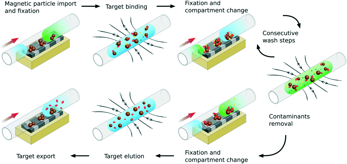 | ||
| Fig. 1 Basic operation principle of particle-based biomolecule separation in a compartmented capillary. The panels show the crucial process steps (particle import, target binding, wash steps, target elution and export) as well as the corresponding magnetic field state (permanent magnetic field for particle fixation and electromagnetic field for resuspension). The applied flow is indicated by a red arrow. | ||
Initially, magnetic particles with suitable surface functionality for reversible target binding are imported into the device in discrete reaction compartments, separated by an immiscible fluid segment or by air. The compartment is centered in the reaction module and the particles are fixed to the capillary wall in defined pellets by means of movable permanent magnets. An applied flow then separates the accrued particle pellets from their transportation compartment. Subsequently, the crude blood cell suspension, containing the target as well as contaminants, is pumped into the center of the reaction module, and hence unified with the particle pellets. For target binding, the permanent magnets are removed and a uniform, phase shifted alternating electromagnetic field (AC-field) is activated to control the magnetic particles, actuating and forcing them to orient along the magnetic field lines. Consequently, the particles are redispersed inside the fluidic compartment. As a result, maximum exposure of the particle surfaces towards the surrounding fluid is achieved. After the time allowed for binding has passed, the AC-field is deactivated and the particles sediment to the capillary wall. Additionally, the permanent magnetic field is used to fix the particles while the compartment is changed. Compartments containing a wash buffer of the desired composition can now be sequentially pumped over the particles to remove any process contaminants in a stepwise manner. Finally, the isolated target can be eluted into the desired fluidic environment and exported for further analysis or use.
2.2 Structure of the device
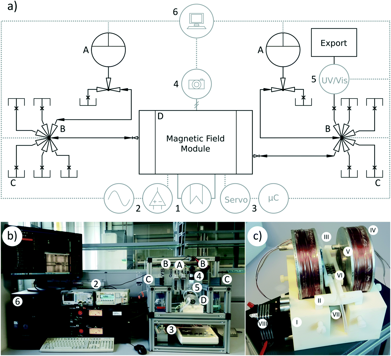 | ||
| Fig. 2 Setup of the device for magnetic particle-based isolation of biomolecules. a) General flow scheme, b) photograph of the developed system. Dosing units (A) are connected to multivalves (B) in order to transport all process relevant fluids and magnetic particle suspensions from reservoirs (C) into the magnetic field module (MFM) (D). The MFM is water-cooled (1) for long term operation and can produce magnetic fields for particle separation and resuspension. Resuspension is achieved using alternating electromagnetic fields generated with the help of a function generator and amplifiers (2). For separation, the MFM has an integrated permanent magnet array that is moved by a servo controlled by a microcontroller (3). A wired USB camera (4), and an integrated spectrometer (5), allow online monitoring of particle movement and fluid composition. All modules are connected to a PC (6) for automation software-driven control. Fluids containing the target compounds as well as washing and waste compartments can also be collected in different reservoirs with the help of a second multivalve. c) Detailed image of the MFM for magnetic particle processing. A compact baseplate (I) positions a capillary holder (II) that centers a reaction capillary (III) between two coils (IV). The coils generate an electromagnetic field for particle resuspension that can be increased by inserting mild steel cylinders (V). For automated separation, a permanent magnet array (VI) is mounted beneath the capillary on a lever (VII) that is moved by a standard servo (VIII). | ||
Two pulsation-free low pressure syringe pump modules were equipped with 5 mL gastight borosilicate glass syringes terminated with a polytetrafluoroethylene Luer lock purchased from Hamilton (Reno, USA). The default operation parameters in this configuration allowed a minimum flow rate of approximately 180 nL s−1, a maximum flow rate of 250 μL s−1 and a pressure limit of 6 bar. The dosing unit comprises an automatic 3/2-way solenoid valve that enables automated refilling cycles, and therefore long term pseudo-continuous flow operations.
Two multiposition valve modules equipped with a Rheodyne TitanHP™ 6-position, 7-port motorized valve from IDEX Corp. (Rohnert Park, USA) were plugged into the device. These multivalves accept 10–32 male fittings for 1/16′′ tubes. The valve stator contains flow passages that are 300 μm in diameter and the rotor seal has a diameter of 250 μm resulting in a port-to-port dead volume of 415 nL. Depending on the connected adapters and tubes, these multivalves have a working pressure maximum of 414 bar.
The spectrometer module houses an online spectrometer consisting of a UV/vis detector and an external deuterium tungsten halogen illuminant wired with a short-range optical fiber (Ø = 400 μm). This module was pre-configured and ready for UV and VIS application measurements in the wavelength range from 220 to 650 nm. The length of the optical path could be adjusted by simple replacement. In the configuration used for this project, the measurement channel length was 5 mm and the internal volume was approximately 9 μL.
To connect the external components, an input and output (I/O) module that contains a variety of analog and digital inputs and outputs was used in the device. In the used setup, the I/O element was used to integrate the control of the two electromagnetic coils that set up the electromagnetic fields and the servo that positioned the permanent magnet array into the QmixElements automation software.
Additionally, a digital USB camera microscope DigiMicro Scale purchased from dnt (Dietzenbach, Germany) was added to the setup. The camera hosted two megapixels of imaging sensor elements able to produce full high definition videos up to a maximum frame rate of 30 images per second at a maximum of 200-fold magnification. Being centered above the particle handling area, the camera was suitable for overall monitoring. After integration into the automation software, automated optical process evaluation could be conducted.
MFM setup. The baseplate of this compact module with overall dimensions of 110 × 100 × 100 mm is a block with semicircular cavities to hold the two electromagnectic coils. This holding block was manufactured out of a photopolymer of complex composition, containing acrylic monomers and epoxy acrylates inter alia, using the PolyJet technology of the Objet EDEN 260 VS from Stratasys (Rheinmünster, Germany).
Besides the cavities for the electromagnetic coils, the holding block also contains four bores to connect a height adjustable capillary holder. This capillary holder is another 3D-printed part ready to take up and position a 1/8′′ capillary in the median plane of the coil arrangement. Due to the simple clipping mechanism for inserting the capillary, this construction also allows quick replacement of the capillary if necessary. To bring the capillary into direct contact with the permanent magnet array installed underneath, the holder provides a gap that fits the magnet array lever geometry.
To create an increased reaction compartment volume, the capillary in the MFM had an outer diameter of 1/8′′ and was, on each side, connected to the periphery via 1/8′′–1/16′′ ethylene tetrafluoroethylene (ETFE) junctions purchased from CS-Chromatographie Service. If smaller compartment volumes are required, this arrangement can be easily replaced with e.g. a single 1/16′′ capillary.
The system for resuspending previously separated or sedimented magnetic particles is based on an arrangement of two electromagnetic coils, each with 80/70 mm outer/inner diameters and a width of 20 mm, which were wrapped with 720 isolated copper wire windings (Ø = 0.5 mm, R = 0.087 Ω m−1). The coil bobbins were manufactured from anodized aluminum and contained a 55/30 mm outer/inner diameter cooling loop. To enhance and polarize the magnetic field in the space between the coils, two cylinders of 30 mm height and 30 mm diameter were fabricated from mild steel (permeability μr = 911) and were placed in the center of each coil. The coils were mounted in analogy to the defined Helmholtz arrangement at a distance of 55 mm. For automated magnetic particle separation, a permanent magnet array was mounted on a 3D-printed lever. This lever was connected to a driveshaft that was moved by a standard servo.
MFM operating modes. The sinusoidal current signal feeding the coil arrangement originates from a DG1022 arbitrary waveform function generator purchased from Rigol Technologies Inc. (Beijing, China), which is capable of emitting fully adjustable alternating current (AC) signals in two independent output channels. Each signal was subsequently amplified by a separate 19Z/500 amplifier purchased from FG-Elektronik GmbH (Rückersdorf, Germany). For all experiments, the current delivered to the coils was 3 A after amplification. The experiments were performed in the extremely low frequency range at 0.1 Hz and 1 Hz. Additionally, a phase shift of 90° was applied to one of the channels. The previously described I/O module is interconnected within the signaling lines between the function generator and the coils to allow automation software-driven generation of time-dependent, script-based electromagnetic fields. Additionally, an I/O module-independent operation mode, e.g. for maintenance servicing, was installed.
The commands for the servo driven lever movement, controlling the permanent magnet array for magnetic particle fixation, are given by a Genuino MICRO single-board microcontroller (μC), which was purchased from Arduino (Turin, Italy). This assembly is based on an ATmega32U4 microcontroller and equipped with numerous general-purpose I/O generic pins that can be programmed easily with an open-source integrated development environment.30 Two servo positions were predefined in the μC, moving the permanent magnet array either at the outer surface of the reaction capillary or far away from this position. As already described for the coil arrangement, the μC was also connected to the I/O module to achieve time- and script-dependent control via the automation software.
3 Materials and methods
3.1 Materials
The chemagic DNA Blood250 Kit31 used for DNA purification inside the reactor device, as well as in tube-based reference experiments, was obtained from PerkinElmer. Blood collection was organized by the Medical Services, Karlsruhe Institute of Technology (KIT) (Eggenstein-Leopoldshafen, Germany) in compliance with national laws and institutional guidelines. The donor was healthy and the blood was tested for infectious diseases. Informed consent was obtained from the donor by the KIT medical staff.
3.2 Methods
For the separation of magnetic particles, a permanent magnet arrangement was developed containing three spots with equal magnetic flux density. Simulation experiments testing several permanent magnets and soft magnetic spacer sizes as well as geometries were performed using the magnetostatics equations package in the finite element analysis software QuickField 5.7 from Tera Analysis (Svendborg, Denmark).32
The electromagnetic field to resuspend previously separated or sedimented magnetic particles inside a fluidic environment is based on an arrangement of two electromagnetic coils mounted in a Helmholtz arrangement. Helmholtz coils are a promising approach to agitate magnetic particles. They have been widely used to generate uniform magnetic fields and, due to the easy construction and magnetic field calculations, they are useful for numerous, especially low-frequency, magnetic field applications in different fields of research, e.g. to calibrate and to test magnetic probes and sensors, for conductive microparticle detection and for magnetic force driven drug delivery.33,34 For further information concerning the coil system setup see section 2.2.
To confirm and characterize the Helmholtz coil, the magnetic flux density in the center plane between the coils was measured under direct current conditions at 2 A, provided by a SEC 3034D switching power supply unit purchased from Pentair Schroff (Straubenhardt, Germany). The measurement was conducted using a transverse Hall probe mounted on a FH 31 Gaussmeter from Magnet-Physik Steingroever GmbH (Köln, Germany). In order to verify the Hall probe results, the numeric computing simulation environment Maple 18.02 from Maplesoft (Waterloo, Canada) was used. As derived by Huber and Urban, the magnetic field can be directly calculated using the Biot-Savart law for linear segments and arbitrary points on the Helmholtz coil axis.35 However, the calculation of off-axis values of the magnetic field is more complex. Kirschvink has reported a numerical method to calculate off-axis magnetic field values.36 For a detailed description of the calculations see supplement 3.‡
Dosing accuracy. The dosing accuracy of the fluidic system was investigated by recording real time videos of the generated aqueous compartments at different volumetric flow rates and target volumes using the reactor device integrated digital USB camera microscope. Besides air, the formation of compartments was tested using three different types of water immiscible separator fluids (ethyl acetate, n-decane, and low viscosity polydimethylsiloxane oil). One port of the first multivalve was connected to a tank holding 1 ‰-dyed ddH2O (turquois ink 4001, Pelikan, Hannover, Germany). Another port of the same multivalve was connected to a reservoir containing the separator fluid. A process script was used to tell the valve to alternate between the two ports. After each change of position of the valve, a flow was generated by drawing liquid (or air) from the reservoirs up into a syringe. As a result, defined amounts of liquid (or air) were automatically withdrawn into the reaction capillary. Long sequences of alternating fluids were produced resulting in a high number of analyzable compartments. The recorded raw video was processed using Magix Video Deluxe 2016 video editing software from MAGIX (Berlin, Germany), and screenshot sequences in defined intervals depending on the applied flow rate were exported. Based on the ImageJ37 distribution FIJI,38 the area of each compartment was measured and subsequently its volume was calculated. This made it possible to directly quantify the dosing accuracy of the reactor device under a certain process condition. A detailed description of the compartment volume calculation process can be found in supplement 5.‡
Cross-contamination. With respect to cross-contamination and washing efficiency, it is important to get an insight into the carry-over of process fluids from one aqueous compartment to another in the course of transferring magnetic particles between them. Therefore, carry-over experiments monitoring cross-contamination at different volumetric flow rates, as well as with a variety of particle concentrations, were conducted.
Initially, a defined amount of M-PVA particles was washed once with 0.5 M sodium chloride and subsequently five times with 10 mM sodium-phosphate buffer (pH 7.5) in excess and automatically imported into the magnetic field module. All compartments and separator segments had a volume of 50 μL. The experiments with different volumetric flow rates in the range from 5 up to 100 μL s−1 were performed at a particle concentration of 5 g L−1, and all experiments investigating the particle concentration in the range from 0 up to 20 g L−1 were executed at a fixed flow rate of 10 μL s−1. As tracer substance, 50 μM eosin Y, was dissolved in 10 mM sodium-phosphate buffer (pH 7.5), while pure 10 mM sodium-phosphate buffer (pH 7.5) was used in the receiving compartment. The experimental setup contained liquid–liquid separated compartments, with ethyl acetate as a representative separator fluid, as well as liquid–gaseous (air) separated compartments. The particles were separated for 30 s and resuspended at 1 Hz/3 A for 30 s in each aqueous compartment. The sequence was as follows: separator fluid–tracer solution–separator fluid–tracer solution–separator fluid–receiving solution–separator fluid. In this sequence, the first tracer compartment served as a primer to prepare the particles for the second tracer compartment. After the particles were electromagnetically resuspended in the second tracer, a 50 μL receiving compartment was pumped over the magnetic particles and, after resuspension, directly investigated within the integrated UV/vis module by absorbance measurement at 520 nm. Finally, a previously produced calibration curve with defined amounts of eosin Y (0–15 μM) was used to quantify the concentration of eosin in the receiving compartment.
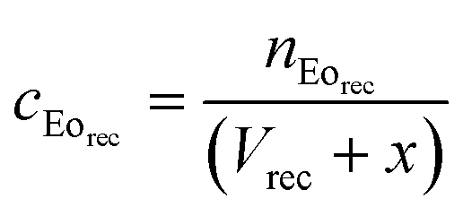
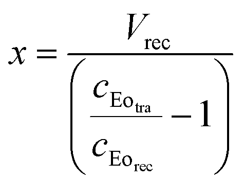
Eqn (1) calculates the carry-over volume, wherein the concentration of eosin in the receiving compartment (μmol μL−1) is expressed as the amount of eosin (μmol) divided by the initial compartment volume (μL) and the added carry-over volume x (μL). In addition, the amount of eosin in the receiving compartment (μmol) equals the concentration of eosin in the tracer solution (μmol μL−1) multiplied by the carry-over volume x (μL) (eqn (2)). Substituting eqn (2) into eqn (1) and solving for x gives eqn (3), which can be used to quantify the carry-over volume (μL).
 | (1) |
| nEorec = cEotrax | (2) |
Substituting (2) into (1) and solving for x:
 | (3) |
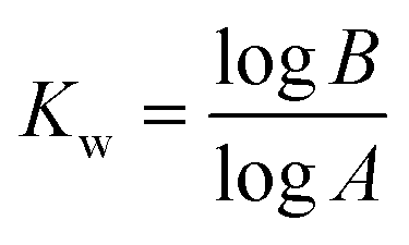
Additionally, the number of required wash cycles (Kw) for all of the above stated volumetric flow rates and particle concentrations was calculated according to eqn (4). In this equation, A represents the percentage of the liquid in an aqueous compartment which is transferred into the next aqueous compartment when particles are transferred between them, and B depicts the maximum percentage of tolerable cross-contamination. In this case, the number of wash volume equivalents, which is equivalent to the number of washing steps, can be calculated.
 | (4) |
Particle characterization. Preliminary characterization of the magnetic particles as well as the aftermath of the magnetic particle handling in the reactor device was performed with the following methods. For particle size and distribution measurements with an EyeTech particle size analyzer from Ankersmid (Nijverdal, Netherlands), particle suspensions (5 mg L−1) in H2O were used. To further investigate the impact of particle processing on the morphology of the processed particles, environmental scanning electron microscopy (ESEM) was performed using an XL30 ESEM-FEG from Philips (Amsterdam, Netherlands). To investigate the iron fraction in the composites, inductively coupled plasma optical emission spectroscopy (ICP-OES) analysis using an Optima 8300DV spectrometer from PerkinElmer (Waltham, USA) was performed, and the amount of magnetic iron oxide (MIO) was subsequently calculated. The magnetic properties of the particles, in particular the saturation and residual magnetization, were measured using a MicroMag 2900 alternating gradient magnetometer from Princeton Measurements Corporation (Westerville, USA).
Permanent magnet-driven particle separation. The particle separation efficiency of the permanent magnet array was investigated. Initially, 300 μg of particles was imported into the reactor device and electromagnetically resuspended at 100 mHz/3 A for 120 s in a 30 μL aqueous compartment separated by a 50 μL compartment of n-decane on each side. After resuspension, the particles were separated for 30 s by bringing the capillary into contact with the permanent magnet array by raising the respective lever arm. Subsequently, the compartment was exported and a fresh aqueous compartment was pumped over the magnetic particles at a flow rate of 25 μL s−1, and resuspension was repeated. The transposition of an aqueous compartment correlates with the exposure of the separated particles to two moving liquid–liquid interfaces (particles leaving the aqueous compartment and entering the separator fluid segment and vice versa). For each particle type, this procedure was performed eight times. Subsequently the aqueous compartments, including the n-decane separator fluid, were pooled and the iron content was determined using ICP-OES analysis, followed by calculation of the loss of particles during one separation process.
Electromagnet-driven particle resuspension. Besides separation, effective resuspension of the magnetic particles is also a crucial parameter for the successful operation of the device. Therefore, the efficiency of electromagnetic particle resuspension was investigated.
Firstly, the general resuspension ability of all the considered magnetic particles was examined. To do this, 10 g L−1 particles were electromagnetically resuspended in 10 mM sodium phosphate buffer (pH 7.5) at 100 mHz/3 A, as well as at 1 Hz/3 A, with a phase shift of 90° applied on one of the channels. The coils were equipped with the previously mentioned mild steel cylinders.
In a second series of experiments, the impact of polarity and ionic strength on magnetic particle resuspension was investigated. To do this, M-PVA particles were imported into the reactor device and electromagnetically resuspended at 100 mHz/3 A. Particle resuspension was monitored over a time frame of five minutes. The experiments were performed at a particle concentration of 10 g L−1 in 80 μL compartments with an increasing ethanol fraction ranging from 0 to 60% v/v, as well as in a fluidic environment with an increasing molarity of sodium chloride up to 2.5 M. The evaluation of the resuspension was done optically with the help of process videos recorded with a reactor device implemented microscope camera by measuring the time until all three particle pellets had dissolved.
To further investigate the impact of the electromagnetically driven resuspension of magnetic particles inside the magnetic field module, all particle types were exposed to the previously described electromagnetic field at 100 mHz/3 A for one hour in a third experiment. Here, one electromagnetic particle resuspension cycle consisted of four minutes of resuspension followed by 30 seconds of sedimentation and a subsequent 30 seconds of permanent magnet driven particle fixation. The particle concentration was 10 g L−1 and the fluidic environment consisted of 10 mM sodium phosphate buffer (pH 7.5). After the experimental time had passed, the particle size and distribution were measured as previously described.
DNA purification in the reactor device was performed according to manufacturer's protocol31 with slightly modifications as follows. Prior to a typical experiment, 7 μL of particle suspension including 30% w/w admixed strontium ferrite was diluted in 100 μL of binding buffer. The suspension was then injected into the device and automatically positioned and separated in the center of the MFM. For cell lysis, 29 μL of lysis buffer was added to 23 μL of blood and incubated under agitation for 1 min at room temperature. Then, 77 μL of binding buffer was added to the lysed blood, and subsequently a 100 μL sized compartment was transported into the center of the MFM, merged with the magnetic particles and, for DNA binding, resuspended for 15 min. After binding, the compartment was exported and discarded. The magnetic particles were washed under resuspension three times, with each wash consisting of 250 μL of wash buffer 4 for 3 min followed by 250 μL of wash buffer 5 for 3 min, to remove contaminants, proteins and cell debris. To remove residual wash fluid after the wash cycles, wash buffer 6 was pumped over the separated particle pellets for 30 s. Elution of the purified DNA was performed by resuspending the particles in 50 μL of 10 mM sodium phosphate buffer (pH 8) for 15 min. The eluted DNA was analyzed in the UV/vis spectrometer module by absorbance measurement at 260 nm and 280 nm, and quantified using a previously produced calibration curve with defined amounts of DNA from salmon testes (0–50 μg mL−1). Finally, the DNA was exported from the reactor device into a microcentrifuge tube for storage and further use.
In order to evaluate the potency of the reactor device, a control experiment was performed, which involved the manual isolation of DNA in microcentrifuge tubes. For this purpose, equal amounts of process fluids and comparable reaction conditions were applied. Analysis and quantification of the eluted DNA was performed in the reactor device integrated spectrometer module as previously described.
Both the DNA sample purified by the device and the sample isolated manually were further investigated. The integrity of the samples was analyzed by amplifying a gene fragment of the glyceraldehyde phosphate dehydrogenase (GADPH) housekeeping gene (amplicon size 267 bp). This was done using a preparation size of 50 μL following a modified protocol described by Oster et al.39 Briefly, 1.5% v/v of eluted DNA was used as a template for amplification and 5 pmol each of the forward (GADPH-F: 5′-ACAGTCCATTGCCATCACTGCC-3′) and reverse primers (GADPH-R: 5′-GCCTGCTTCACCACCTTCTTG-3′) were added. Ten times PCR buffer was added to a final concentration of one. Subsequently, dNTPs at a final concentration of 0.2 mM and 0.5 μL of Taq-polymerase were added to catalyze the reaction. PCR was conducted in a 2720 Thermal Cycler from Applied Biosystems (Foster City, USA) using the following reaction conditions: 4 min of initial denaturation at 94 °C followed by 34 amplification cycles of 0.5 min at 94 °C, 0.5 min at 61 °C and 1 min at 72 °C, followed by a final extension of 10 min at 72 °C. Finally, appropriate product amplification was checked by agarose gel electrophoresis.
4 Results and discussion
4.1 Magnetic field characterization
Optimization of the arrangement of the permanent magnets and the field polarizing mild steel sheets by applying finite element analysis resulted in an array construct capable of producing three well-defined spots for particle fixation as shown in Fig. 3a. Here, three antipolar stacked nickel-plated neodymium plates (10 × 10 × 1 mm) with a coercive force strength of 955 kA m−1, tailor-made by HKCM Engineering (Eckernförde, Germany), were separated by mild steel sheet stacks of the same geometry and a coercive force strength of approximately 1 kA m−1. The magnets, as well as the steel sheets, contained semicircular gaps to enhance the contact with the reaction capillary and thereby strengthen the magnetic force on the magnetic particles.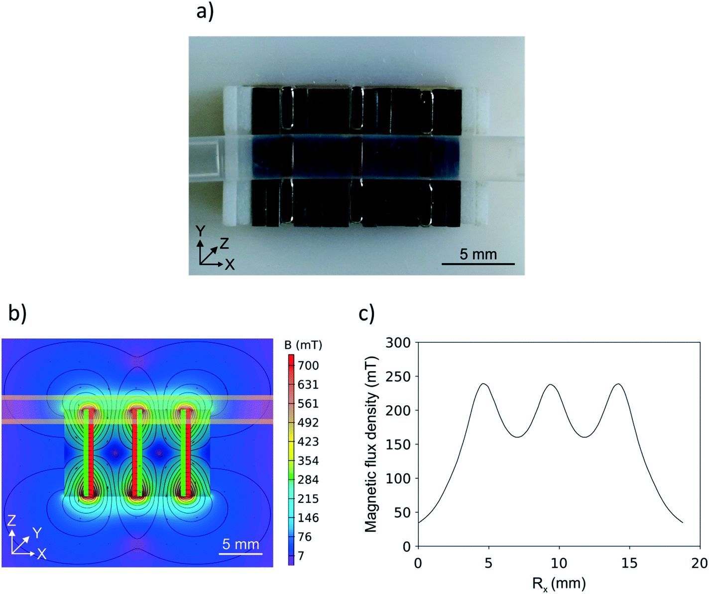 | ||
| Fig. 3 a) Top view of the constructed permanent magnet array touching the reaction capillary and therefore retaining M-PVA particles in three well-defined separation spots. b) Side-view contour-plotted magnetic flux density of the array, including field lines and magnetic flux vectors. The magnetic poles of the antipolar stacked magnetic plates are indicated in red and green, and the mild steel sheets are grey. The position of the reaction capillary is indicated in light yellow. c) Spline curve of the magnetic flux density along the x-axis at a distance of 1.05 mm from the magnet array. | ||
Fig. 3b shows the simulated magnetic field, including field lines and magnetic flux vectors. The polarity of the magnets, separated by the grey steel sheets, is indicated in red and green. Additionally, the position of the capillary is indicated in light yellow. Fig. 3c shows the spline curve of the magnetic flux density forces acting along the x-axis at a distance of 1.05 mm from the array surface. This distance represents the furthest point of the reaction capillary inner diameter from the magnet array. Even here, the permanent magnet array produced well-defined spots of approximately 245 mT flux density, which is suitable to effectively retain the magnetic particles during applied fluidic flow.
The magnetic field distribution of the coil-based electromagnetic field, used to resuspend previously separated or sedimented magnetic particles inside a fluidic environment, was measured with a Hall probe inside the area of the median plane of the coils at the height of the installed reaction capillary, under direct current conditions at 2 A without inserted mild steel cylinders. The field reached a plateau with a homogenous magnetic flux density of approximately 25 mT between the two coils. To verify the settings, the field uniformity was additionally numerically calculated as described in supplement 3.‡ The contour plots of the magnetic field uniformity of the MFM gained from the Hall probe measurements compared to the results of the numerical computing simulations can be found in supplement 4.‡
4.2 Compartment generation and characterization
| Name | Interfacial tension γ between separator fluid and water at 293–300 K [mN m−1] | Density ρ [kg m−3] | Dynamic viscosity η at 298 K [Pa s] | Kinematic viscosity ν [m2 s−1] | Ref. |
|---|---|---|---|---|---|
| a Calculated. | |||||
| Ethyl acetate | 6.8 | 900 (293 K) | 4.2 × 10⁻⁴ | 0.47 × 10⁻⁶ (298 K) | 40–42 |
| n-Decane | 52.0 | 730 (293 K) | 8.4 × 10⁻⁴ | 1.15 × 10⁻⁶ (293 K) | 40, 42, 43 |
| PDMS oil | 41.0 | 913 (298 K) | 4.9 × 10⁻³a | 5.00 × 10⁻⁶ (298 K) | 40, 44, 45 |
| Air | 72.0 | 1.20 (293 K) | 2.0 × 10⁻⁵ | 1.55 × 10⁻⁵ (298 K) | 40, 46 |
As shown in Fig. 4, the resulting aqueous compartment volumes differ substantially depending on the used separator fluid. The compartments separated by EtOAc and Dec segments (Fig. 4a and b), which exhibit a lower kinematic viscosity than PDMS oil, showed good volume reproducibility, indicating that the compartments were stable over the entire range of target volumes and applied flow rates. Here, all standard deviations were less than 10%. An exception was found for small volume (10 μL and 50 μL) Dec-separated compartments generated at low flow rates. The desired target volume could be achieved for Dec-separated compartments of 10 μL, 50 μL and 100 μL size over the entire examined flow rate range, except for the above mentioned conditions. It should be noted that the compartment size slightly decreased with increasing flow rate for EtOAc- and air-separated compartments. Looking at the properties of EtOAc and especially air, the most likely explanation is the low dynamic and kinematic viscosity of these fluids compared to H2O. The required flow for the formation of compartments is generated during the loading process of the syringe pump, therefore the fluids are withdrawn into the capillary. During this process, especially high flow rates create negative pressure situations inside the capillary. The low viscosities of EtOAc and air facilitate pressure equalization during the formation of the separator fluid segments, resulting in an enlarged volume and subsequently a decreased volume of adjacent aqueous compartments inside the reaction capillary (Fig. 4a and d). Nevertheless, when working with aqueous compartments of complex composition (e.g. lysed cell suspensions containing hydrophibic and hydrophilic enzymes or blood samples) where the compounds might interact with organic separator fluids, separation by air often is the best approach for overall process performance.
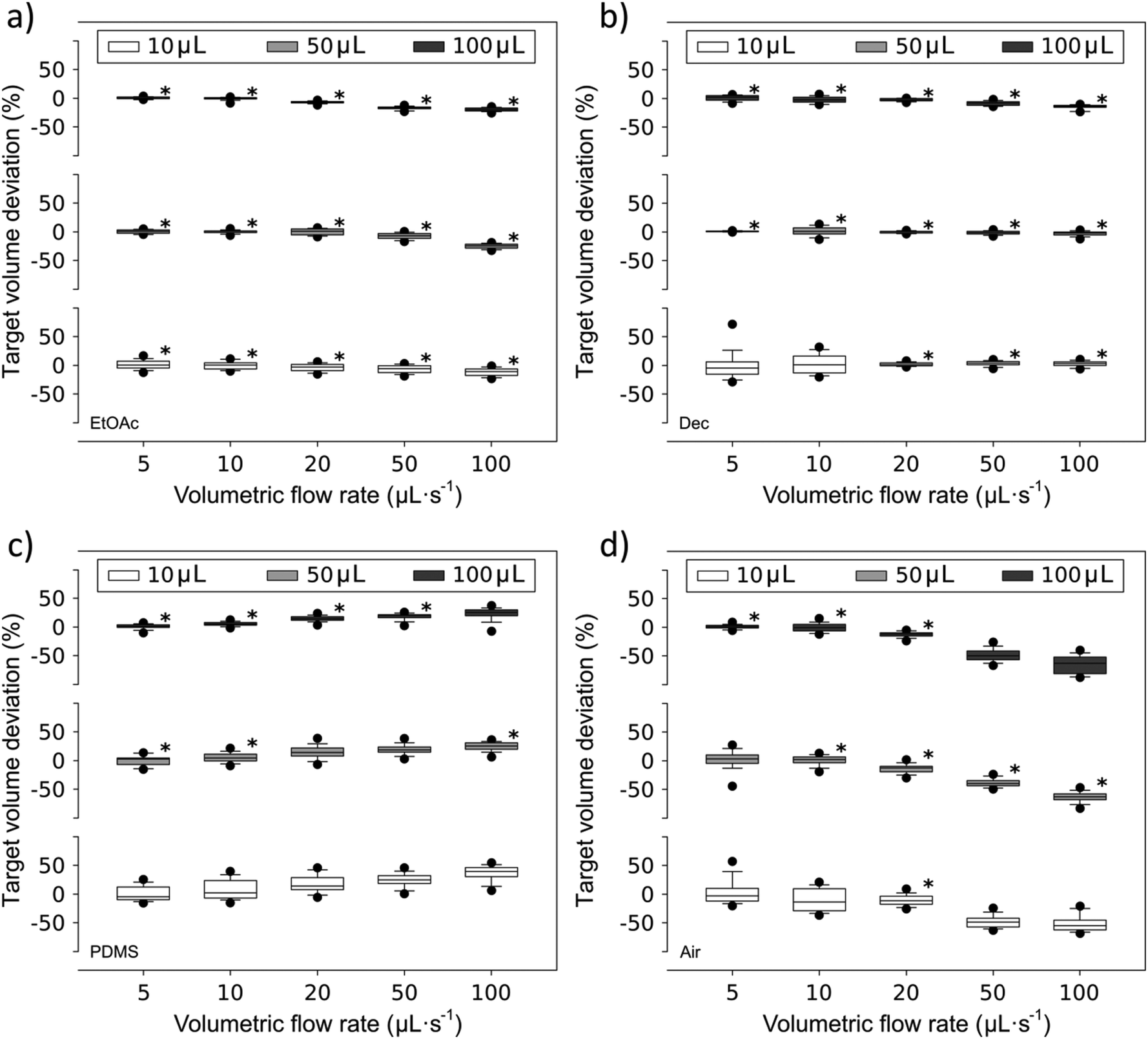 | ||
| Fig. 4 Summarized results of 10 μL, 50 μL and 100 μL generated aqueous compartments separated by a) ethyl acetate, b) n-decane, c) polydimethylsiloxane oil and d) air at flow rates ranging from 5 up to 100 μL s−1. The y-axis depicts the deviation from the target dosed volume. * indicates less than or equal to 10% deviation. | ||
PDMS has a high dynamic viscosity compared to EtOAc, Dec, air and H2O. Aqueous compartments separated with PDMS (Fig. 4c) showed a slightly worse volume reproducibility. While dosing large 100 μL as well as 50 μL compartments at slow volumetric flow rates still showed a good target volume deviation of less than 10%, small compartments generated at high flow rates showed a positive volume deviation, in accordance with the viscosity difference effects described above.
A direct correlation between increasing flow rate and the amount of liquid that is carried by the 5 g L−1 particles and the capillary walls into the next aqueous compartment could be found (Fig. 5a). Here, the cross-contamination increased for both EtOAc- and air-separated compartments until it reached a plateau at 50 μL s−1. After that, a higher flow rate did not result in higher cross-contamination. The EtOAc-separated compartments showed a higher carry-over overall, ranging from approximately 2.8% at a flow rate of 5 μL s−1 up to circa 4.8% at a flow rate of 100 μL s−1.
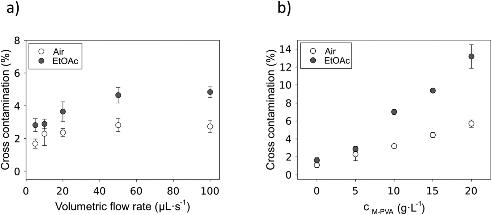 | ||
| Fig. 5 a) Cross-contamination of EtOAc- and air-separated compartments at a particle concentration of 5 g L−1 and different volumetric flow rates from 5 μL s−1 up to 100 μL s−1. b) Particle concentration (5 g L−1–20 g L−1) dependent cross-contamination of EtOAc- and air-separated compartments at a volumetric flow rate of 10 μL s−1. | ||
Cross-contamination at increasing particle concentrations conducted at a fixed flow rate of 10 μL s−1 is shown in Fig. 5b. It is important to note that the particle concentration has a smaller impact on cross-contamination when the compartments are separated by air. Here, without any particles, the carry-over was 1.1%, while at high particle concentrations it only increased by roughly 4.5%. A direct correlation between the carry-over and the particle concentration applied in the compartment could also be detected for EtOAc-separated compartments. Here, cross-contamination ranging from 1.6% without particles up to 13.2% with an applied particle concentration of 20 g L−1 highlights the impact of particle concentration on the carry-over volume in EtOAc-separated setups. On the one hand, air as a separator fluid, exhibiting a high interfacial tension with water, seems to be able to strip off the aqueous solution from the hydrophobic capillary walls and the particle pellets almost completely. On the other hand, while using EtOAc as a separator fluid, the aqueous solution is trapped on the surface and in the interstitial volume of the particle pellets, and therefore carry-over strongly increases with the amount of particles in the compartment.
As can be seen from eqn (4), cross-contamination and wash cycles (Kw) directly correlate. In most cases, only three washing cycles are needed to reduce cross-contamination to below 0.1 ‰, demonstrating the suitability of the reactor device for sensitive analytical processes.
4.3 Particle processing
To prove the suitability of the reactor device for a diverse range of magnetic particles representing a broad field of potential applications, a collection of five mono- and polydispersed, spherical magnetic particles from different commercial manufacturers were processed in the device and characterized towards process-relevant parameters. All examined particles consist of a magnetic iron oxide (MIO) component incorporated into a polymeric matrix structure. However, they differ in size, ferromagnetic content and polymer matrix, as well as in their surface functionality and subsequently their magnetic properties. In addition, strontium ferrite was examined and processed in the device as an example of pristine inorganic, strongly magnetic particles. Fig. 6 shows the size and surface morphology of the processed particles imaged by ESEM.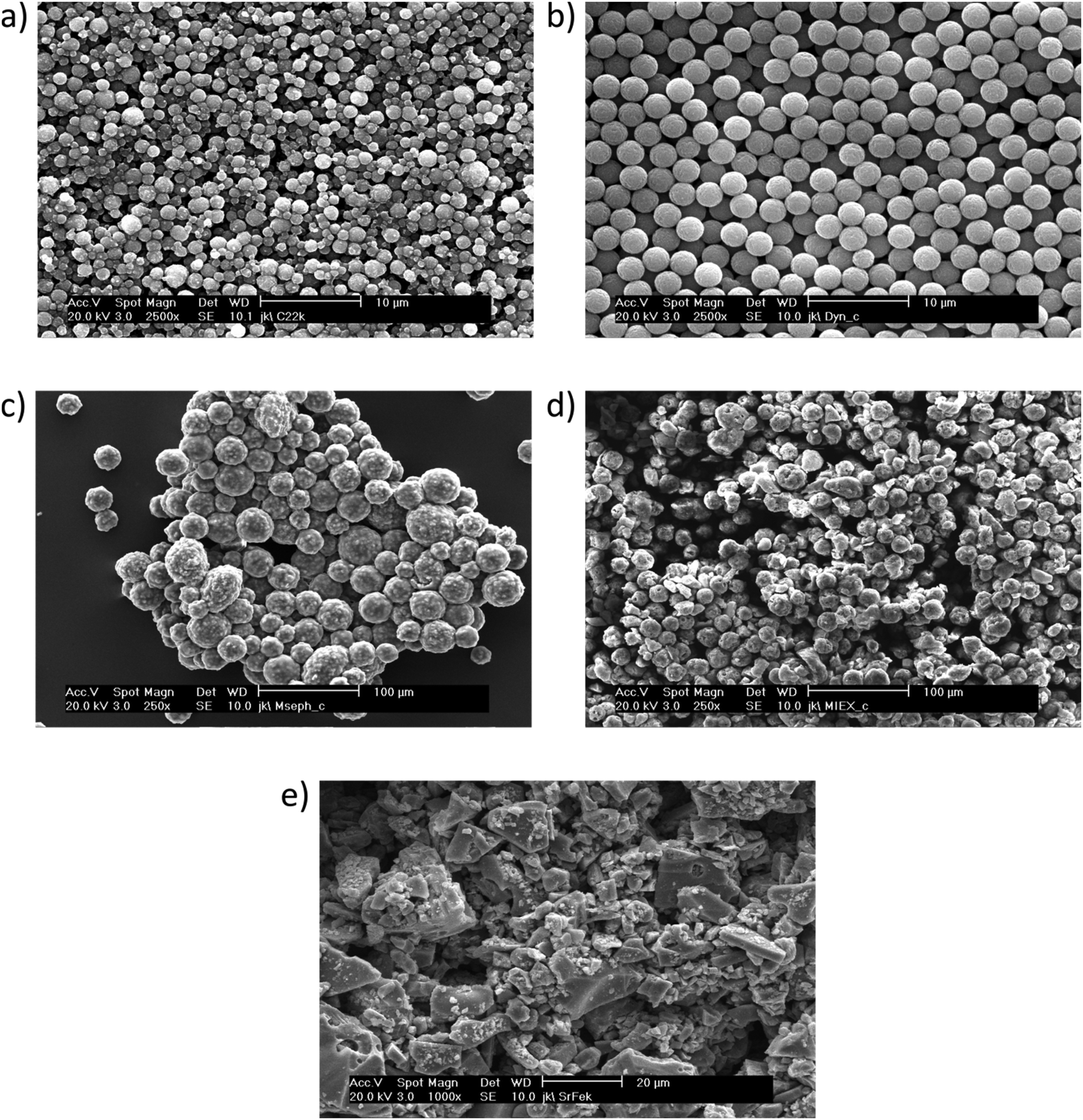 | ||
| Fig. 6 ESEM imaging of different particle types processed in the reactor device. a) M-PVA, b) Dynabeads, c) Mag Sepharose, d) MIEX and e) strontium ferrite. | ||
| Name | Manufacturer | Composition [% w/w] | Surface group | Surface weighted particle diameter [μm] | Magnetism [A m2 kg−1] | |||||
|---|---|---|---|---|---|---|---|---|---|---|
| MIO | Matrix | Ø | d 32 10 | d 32 50 | d 32 90 | M s | M r | |||
| M-PVA | Chemagen PerkinElmer | MT (53.4 ± 2.8) | PVA (46.6)47 | –COOH | 2.3 ± 1.7 | 0.8 | 1.5 | 4.8 | 35.0 | 2.5 × 10⁻² |
| Dynabeads | Thermo Fisher Scientific | MM (20.0 ± 1.0) | PS (80.0)48 | –COOH | 1.4 ± 0.8 | 0.8 | 1.1 | 2.1 | 14.6 | 8.4 × 10⁻² |
| Mag Sepharose | GE Healthcare Life Sciences | MT (57.5 ± 0.7) | Agarose (42.5)49 | –OH | 39.4 ± 16.4 | 15.5 | 41.1 | 58.7 | 47.6 | 6.9 |
| MIEX | Orica Watercare | MM (50.2 ± 0.4) | PGMA (49.8)50,51 | –OH | 20.3 ± 8.2 | 10.4 | 19.7 | 30.0 | 51.7 | 29.5 |
| Strontium ferrite | Sigma-Aldrich | SrFe12O19 (≥99.5) | — | — | 22.5 ± 14.0 | 7.3 | 19.1 | 43.0 | 63.9 | 23.0 |
| Name | m Particle [μg] | Loss mParticle/separation [μg] | Loss mParticle/separation [%] |
|---|---|---|---|
| M-PVA | 300 | 0.033 ± 0.006 | 0.011 ± 0.002 |
| Dynabeads | 300 | 0.135 ± 0.094 | 0.045 ± 0.031 |
| Mag Sepharose | 300 | 0.063 ± 0.043 | 0.021 ± 0.014 |
| MIEX | 300 | 0.016 | 0.005 |
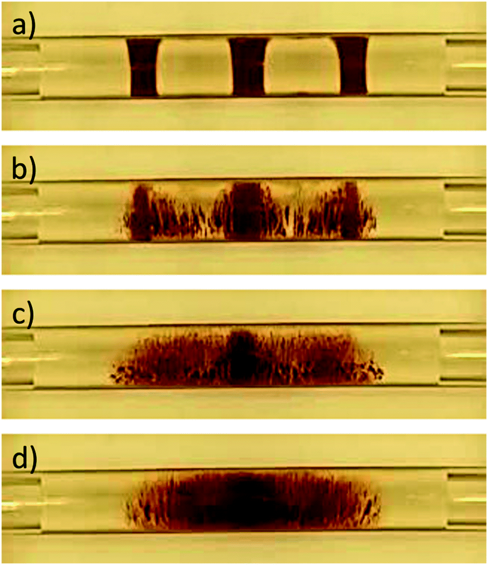 | ||
| Fig. 7 Screenshots at defined times of a typical process video for the evaluation of the resuspension ability of magnetic particles (M-PVA). From the initial state (a), the particles start to resuspend in the applied electromagnetic field. Intermediary states at 4 s (b) and at 8 s (c) show the particle pellets as resuspension proceeds, until all three pellets are fully resuspended at 12 s of resuspension (d). | ||
Table 4 summarizes the results of the general resuspension ability of all the tested particles in 10 mM sodium phosphate buffer (pH 7.5). All particles were resuspendable within approximately 16 s. Strontium ferrite and MIEX particles resuspended nearly instantly inside the fluidic compartment when a 1 Hz alternating electromagnetic field was applied. In these cases, it only took 0.4 ± 0.1 s and 0.6 ± 0.1 s for the three separated spots to completely disappear. The other three particle types needed more time to completely disperse in the fluid. Mag Sepharose particles needed 10.2 ± 3.3 s for resuspension, and M-PVA and Dynabeads required a time of 12.9 ± 3.4 s and 15.6 ± 0.7 s, respectively. The resuspension time and the magnetic properties of the particles, both saturation and residual magnetization, were directly correlated. It is notable that the impact of residual magnetization (Mr) seemed to be higher than the impact of saturation magnetization (Ms). For example, Mag Sepharose, exhibiting a similar Ms compared to MIEX and strontium ferrite but a more than three times lower Mr, resuspended much more slowly in the same fluidic environment. This can be explained by the fact that in the case of particles with moderate to high remanence, the magnetic force exerted on the particles by the alternating field directly depends on the magnetic remanence of the particles.
| Name | Pellet dissolution time [s] | Mean surface weighted particle diameter [μm] | ||
|---|---|---|---|---|
| 1 Hz | 0.1 Hz | Before electromagnetic resuspension | After 1 h electromagnetic resuspension | |
| M-PVA | 12.9 ± 3.4 | 12.9 ± 3.1 | 2.3 ± 1.7 | 2.2 ± 1.6 |
| Dynabeads | 15.6 ± 0.7 | 14.1 ± 1.5 | 1.4 ± 0.8 | 1.5 ± 1.1 |
| Mag Sepharose | 10.2 ± 3.3 | 11.8 ± 1.2 | 39.4 ± 16.4 | 39.2 ± 16.1 |
| MIEX | 0.6 ± 0.1 | 7.9 ± 0.7 | 20.3 ± 8.2 | 20.9 ± 8.5 |
| Strontium ferrite | 0.4 ± 0.1 | 6.6 ± 2.0 | 22.5 ± 14.0 | 31.2 ± 16.8 |
Resuspending the particles in an electromagnetic field with the same properties but at only 0.1 Hz resulted in similar pellet dissolution times for all particle types. In particular, strontium ferrite and MIEX particles required more time for resuspension due to the ten times longer cycle period. However, the longer cycle period had no impact on Mag Sepharose, M-PVA and Dynabeads, which had resuspension times being the same as previously examined at 1 Hz.
Interestingly, both increasing the fraction of organic solvents and increasing the ionic strength within the aqueous compartment had a negative impact on the resuspension ability of magnetic particles featuring carboxyl surface groups. The presence of ethanol, representing a less polar environment (Fig. 8a), worsened the resuspension of M-PVA particles more than the presence of moderate concentrations of sodium chloride (Fig. 8b). However, the particles did not resuspend in an environment containing more than 2.5 M sodium chloride. Under these conditions, the strong compression of the electrical double layer52 led to decreased repellency resulting in more compact particle pellets. For increasing ethanol concentration, the particle resuspension time increased until the fluid consisted of more than 60% v/v ethanol. Beyond this ethanol concentration, the surface affinity of the hydrophilic particles to the fluidic environment drops below a certain threshold, resulting in persistent particle pellets that were not resuspendable within the monitored time frame of five minutes.
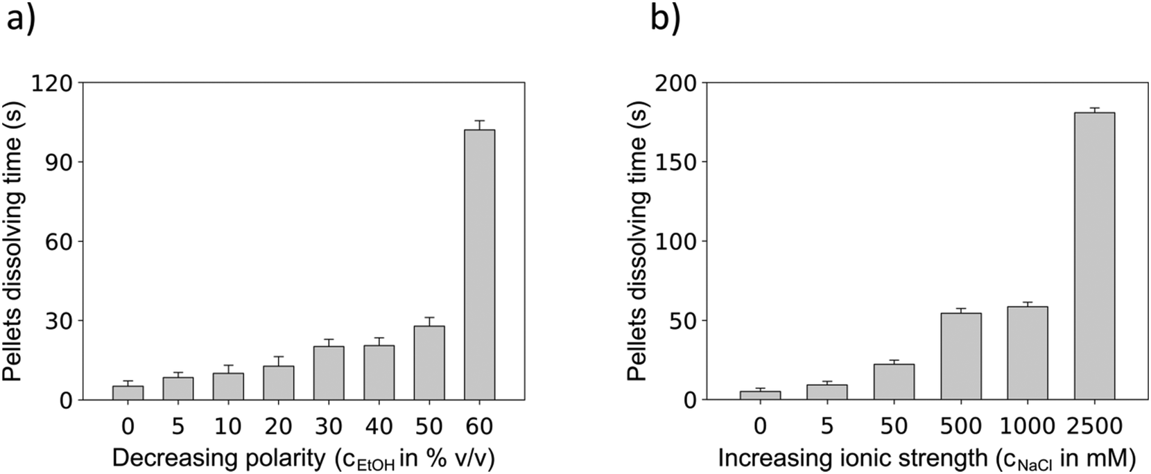 | ||
| Fig. 8 a) Polarity dependent M-PVA particle resuspension. A large increase in resuspension time was observed when the fraction of ethanol went beyond 50% v/v. The particles did not resuspend in a fluid consisting of >60% v/v ethanol within 5 min. b) Resuspension of M-PVA particles in an environment with increasing ionic strength. Within the 5 min time frame, the particles did not resuspend when the sodium chloride molarity increased beyond 2.5 M. | ||
The effect of the mechanical particle movement caused by the electromagnetic field on particle morphology and the effect of the magnetization on the particle size distribution were investigated. Before and after one hour of resuspension–sedimentation–separation cycling, ESEM imaging and particle size distribution analysis were performed. As the ESEM images indicate, no effect on the magnetic particle surface morphology could be detected (supplement 6‡). Furthermore, particle magnetization based on the electrical as well as the permanent magnetic field did not seem to change the particle size distribution. Only for strontium ferrite, which exhibits a high residual magnetization, did the measured size distribution change with the formation of more large-sized agglomerates (supplement 7‡).
4.4 Application example – DNA purification
Whole blood in general, and binding buffer-diluted lysed blood in particular, are suspensions of complex composition and are defined as non-Newtonian fluids.53 These characteristics made the creation of discrete blood compartments separated by fluidic segments difficult. Using aqueous solutions as separator segments led to blood agglutination at the liquid–liquid interface, which resulted in partial clogging of the capillaries and valve ports. When organic solvents were used as the separator fluid the solvent was dispersed within the blood compartment. Separator segments consisting of low viscosity PDMS forced the blood to attach to the capillary wall, and consequently resulted in stratified flow that was not suitable for displacing and positioning the blood compartment within the capillary. However, in contrast, well-defined air-separated compartments containing lysed blood could be generated, and moved and positioned inside the reactor device by applying slow flow rates of approximately 5–10 μL s−1. For consistency, air-separated compartments were used for all of the purification steps in the DNA isolation process.Due to the high saturation magnetization and high residual magnetization properties of the admixed strontium ferrite, the magnetic particles could well disperse in all of the process fluids that contained an extreme proportion of organic solvents, a high ionic strength and an extreme pH value.
As can be seen in Fig. 9a, DNA isolation in the reactor device was comparable to the manual purification process. In the reactor device, the DNA yield was approximately 620 ng per 23 μL of blood sample with a DNA concentration of 12.4 ± 1.9 μg mL−1. This corresponds to approximately 88.6 μg per mL of particle suspension. Comparable results were achieved when performing the DNA isolation manually. In this case, a total of 650 ng of DNA could be isolated with a DNA concentration of 13.0 ± 1.6 μg mL−1. This corresponds to 92.8 μg per mL of particle suspension. Furthermore, the purity of the DNA was similar for both isolation processes, with a 260/280 nm absorbance ratio of 1.7 ± 0.1 for the reactor device and 1.6 ± 0.1 for the manual process.
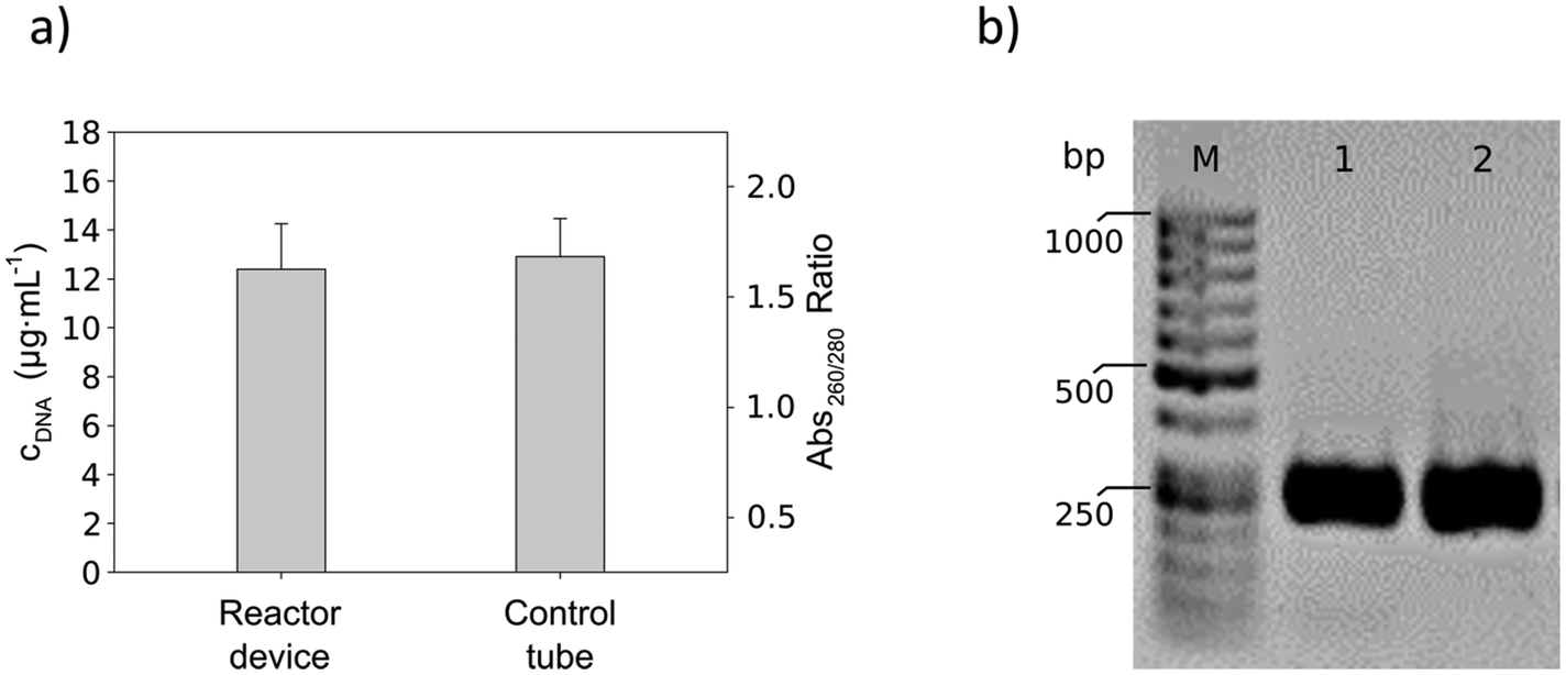 | ||
| Fig. 9 a) DNA purification in the reactor device compared to a manual control. The performance of both procedures was comparable, as can be seen from the DNA concentrations achieved in a 50 μL elution compartment: cDNA reactor device = 12.4 ± 1.9 μg mL−1, cDNA manual control = 13.0 ± 1.6 μg mL−1. b) Agarose gel electrophoresis of 5 μL of PCR product showing the PCR amplified gene fragment (267 bp). 1.5% of each DNA eluate was used as the PCR template. Lane 1 shows the PCR result of the DNA template purified using the reactor device, and lane 2 depicts the PCR amplification of the manually purified DNA template. | ||
The integrity of the purified DNA could be determined by loading the PCR products onto agarose gels. As shown in Fig. 9b, both the sample from the reactor device and the sample from the manual process showed the characteristic band of the amplified gene fragment (amplicon size 267 bp). Hence, product amplification was successful and there was no degradation of the DNA.
Using the reactor device, the isolation process of DNA from a lysed whole blood sample took, including analysis and quantification, approximately 75 min. The manual control performed in microcentrifuge tubes was done in about 60 min excluding DNA analysis.
5 Conclusions and outlook
In this work, a compact fluidic reactor device ready for automated sample-to-answer processes using magnetic particles combining segmented flow and magnetic field technology is presented. Furthermore, the crucial process steps have been mapped.As the results reveal, the device is able to generate a stable segmented flow over a wide range of working conditions using different separator fluids, enabling flexible experimental design. The dosing accuracy for ethyl acetate-, n-decane-, PDMS- and air-separated aqueous compartments, generated at flow rates ranging from 5 up to 100 μL s−1, were studied. Compartment volumes of 10, 50 and 100 μL were achieved, and their reproducibility was evaluated. Moreover, by replacing the reaction capillary, compartments in the range from 1 μL up to 1 mL could be successfully generated (data not shown). Cross-contamination was evaluated covering different common process conditions and the number of wash cycles required to reduce cross-contamination below a certain threshold was calculated, proving that the system is suitable for sensitive analytical processes. Four different commercial magnetic composite particles, as well as strontium ferrite, were successfully handled and processed inside the MFM. Separation efficiency experiments showed that the permanent magnet array is able to effectively separate particles from the fluidic environment and retain them during compartment exchange. The electromagnetic field was able to resuspend all of the tested particle types in aqueous buffers of moderate ionic strength. Here, the resuspension time was between 0.4 and 16 s depending on the magnetic compound fraction. As a result, a toolbox containing different particle types, certain separator fluids and different device operating modes could be developed that can be used to realize different applications.
Finally, a commercially relevant application of a sample-to-answer process, the multi-stage isolation of human DNA from a crude cell suspension including subsequent analysis and DNA quantification, was conducted in the device. Here, it was shown that the device, compared to manual purification, is able to isolate comparable amounts of DNA with equal quality in a yield range suitable for direct processing without intermediate PCR.
In summary, the results show that the developed device is able to fulfill the stipulated requirements. Besides the exchangeable and currently used peripheral units, which could be realized in a much smaller layout, the core of the system is a compact benchtop device for the processing of self-contained automated processes. Due to its modular character and flexible design, the device has the ability to process fluids in separated reaction compartments in a semi-preparative range between 1 and 1000 μL. The designed magnet technology allows the contactless handling of magnetic particles in a large size range. This flexibility was demonstrated by the fast resuspension of large particles with a size of more than 50 μm without any signs of sedimentation, as well as the loss-less separation of 1 μm small-sized particles. The automation of fluidic flow, particle separation and resuspension enables reproducible execution of complex multi-step processes. As a result, the device is suitable for many biotechnological applications, like the isolation and purification of biomolecules, e.g. nucleic acids or proteins, as well as the characterization and substrate screening of immobilized biocatalysts.
To increase the throughput of the device, parallelization should be taken into consideration. Here, the MFM seems to be promising as there is enough room to install parallel reaction capillaries inside the magnetic fields. Peripheral miniaturization should be examined to reduce the overall device dimensions, e.g. signaling components for the electromagnetic field generation could be digitalized. Finally, the possibility for temperature control, a crucial factor for many biotechnological applications, inside the reaction capillary of the MFM should be integrated.
Acknowledgements
The authors want to thank the BMBF project Biotechnologie 2020+ “Die Golgi Glycan Fabrik 2.0” for financial support, Dr. J. Oster (PerkinElmer Chemagen Technologie GmbH, Baesweiler, Germany) for gracefully providing the chemagic DNA Blood250 Kit, Dr. med. V. List (KIT, Eggenstein-Leopoldshafen, Germany) for organizing blood collection and testing and J. Kaltenbach for the help with ESEM imaging.References
- M. A. M. Gijs, F. Lacharme and U. Lehmann, Chem. Rev., 2010, 110, 1518–1563 CrossRef CAS PubMed.
- A. G. Roca, R. Costo, A. F. Rebolledo, S. Veintemillas-Verdaguer, P. Tartaj, T. González-Carreño, M. P. Morales and C. J. Serna, J. Phys. D: Appl. Phys., 2009, 42, 224002 CrossRef.
- N. Tran and T. J. Webster, J. Mater. Chem., 2010, 20, 8760 RSC.
- A. van Reenen, A. M. de Jong, J. M. J. den Toonder and M. W. J. Prins, Lab Chip, 2014, 14, 1966 RSC.
- M. Franzreb, M. Siemann-Herzberg, T. J. Hobley and O. R. T. Thomas, Appl. Microbiol. Biotechnol., 2006, 70, 505–516 CrossRef CAS PubMed.
- S. Rampini, P. Li and G. U. Lee, Lab Chip, 2016, 327, 1072–1074 Search PubMed.
- H. C. Tekin and M. A. M. Gijs, Lab Chip, 2013, 13, 4711 RSC.
- S. Berensmeier, Appl. Microbiol. Biotechnol., 2006, 73, 495–504 CrossRef CAS PubMed.
- R. Taylor, S. Coulombe, T. Otanicar, P. Phelan, A. Gunawan, W. Lv, G. Rosengarten, R. Prasher and H. Tyagi, J. Appl. Phys., 2013, 113, 11301 CrossRef.
- A.-H. Lu, E. L. Salabas and F. Schüth, Angew. Chem., Int. Ed., 2007, 46, 1222–1244 CrossRef CAS PubMed.
- J. Llandro, J. J. Palfreyman, A. Ionescu and C. H. W. Barnes, Med. Biol. Eng. Comput., 2010, 48, 977–998 CAS.
- F. Kong, L. Yuan, Y. F. Zheng and W. Chen, J. Lab. Autom., 2012, 17, 169–185 CrossRef CAS PubMed.
- C. J. Frégeau, C. M. Lett and R. M. Fourney, Forensic Sci. Int.: Genet., 2010, 4, 292–304 CrossRef PubMed.
- Z. Z. Chong, S. H. Tan, A. M. Gañán-Calvo, S. B. Tor, N. H. Loh and N.-T. Nguyen, Lab Chip, 2016, 16, 35–58 RSC.
- P. N. Nge, C. I. Rogers and A. T. Woolley, Chem. Rev., 2013, 113, 2550–2583 CrossRef CAS PubMed.
- E. K. Sackmann, A. L. Fulton and D. J. Beebe, Nature, 2014, 507, 181–189 CrossRef CAS PubMed.
- X. Casadevall i Solvas and A. deMello, Chem. Commun., 2011, 47, 1936–1942 RSC.
- D. Mark, S. Haeberle, G. Roth, F. von Stetten and R. Zengerle, Chem. Soc. Rev., 2010, 39, 1153 RSC.
- A. Huebner, S. Sharma, M. Srisa-Art, F. Hollfelder, J. B. Edel and A. J. deMello, Lab Chip, 2008, 8, 1244 RSC.
- J. Schemberg, A. Grodrian, R. Römer, G. Gastrock and K. Lemke, Phys. Status Solidi, 2010, 207, 904–912 CrossRef CAS.
- P. Sajeesh and A. K. Sen, Microfluid. Nanofluid., 2014, 17, 1–52 CrossRef.
- B. L. Gray, J. Electrochem. Soc., 2014, 161, B3173–B3183 CrossRef CAS.
- N. Pamme, Lab Chip, 2006, 6, 24–38 RSC.
- N. Pamme, Curr. Opin. Chem. Biol., 2012, 16, 436–443 CrossRef CAS PubMed.
- D. Jussen, H. Soltner, B. Stute, W. Wiechert, E. von Lieres and M. Pohl, J. Biotechnol., 2016, 231, 174–182 CrossRef CAS PubMed.
- G. Dutton, Genet. Eng. Biotechnol. News, 2014, 34(10), 12 CrossRef.
- B. Verbruggen, T. Tóth, M. Cornaglia, R. Puers, M. A. M. Gijs and J. Lammertyn, Microfluid. Nanofluid., 2015, 18, 91–102 CrossRef CAS.
- D. Lombardi and P. S. Dittrich, Anal. Bioanal. Chem., 2011, 399, 347–352 CrossRef CAS PubMed.
- J. Hübner, R. Brakowski, J. Wohlgemuth, G. Brenner-Weiß and M. Franzreb, Eng. Life Sci., 2015, 15, 721–726 CrossRef.
- D. Mellis, M. Banzi, D. Cuartielles and T. Igoe, in Proc. CHI, ACM Press, San Jose, USA, 2007 Search PubMed.
- PerkinElmer Inc., chemagic DNA Blood250 Kit - Protoc., 2012, pp. 1–6.
- J. R. Claycomb, Applied Electromagnetics Using QuickField & MATLAB, Infinity Science Press, 2008 Search PubMed.
- R. Beiranvand, Rev. Sci. Instrum., 2013, 84, 75109 CrossRef CAS PubMed.
- D. J. DeTroye and R. J. Chase, US Army Res. Lab., 1994 Search PubMed.
- E. Huber and M. Urban, Helmholtzspulen zur Kalibrierung von Magnetfeldsensoren, Forschungszentrum Karlsruhe GmbH, Karlsruhe, 1995 Search PubMed.
- J. L. Kirschvink, Bioelectromagnetics, 1992, 13, 401–411 CrossRef CAS PubMed.
- C. A. Schneider, W. S. Rasband and K. W. Eliceiri, Nat. Methods, 2012, 9, 671–675 CrossRef CAS PubMed.
- J. Schindelin, I. Arganda-Carreras, E. Frise, V. Kaynig, M. Longair, T. Pietzsch, S. Preibisch, C. Rueden, S. Saalfeld, B. Schmid, J.-Y. Tinevez, D. J. White, V. Hartenstein, K. Eliceiri, P. Tomancak and A. Cardona, Nat. Methods, 2012, 9, 676–682 CrossRef CAS PubMed.
- J. Oster, J. Parker and L. À. Brassard, J. Magn. Magn. Mater., 2001, 225, 145–150 CrossRef CAS.
- D. R. Lide, CRC Handbook of Chemistry and Physics, 94th Edition, 2013-2014, 2013, vol. 53 Search PubMed.
- P. J. Petrino, Y. H. Gaston-Bonhomme and J. L. E. Chevalier, J. Chem. Eng. Data, 1995, 40, 136–140 CrossRef CAS.
- A. H. Demond and A. S. Lindner, Environ. Sci. Technol., 1993, 27, 2318–2331 CrossRef CAS.
- E. F. Cooper and A. F. A. Asfour, J. Chem. Eng. Data, 1991, 36, 285–288 CrossRef CAS.
- S. R. Ranabothu, C. Karnezis and L. L. Dai, J. Colloid Interface Sci., 2005, 288, 213–221 CrossRef CAS PubMed.
- A. E. Ismail, G. S. Grest, D. R. Heine, M. J. Stevens and M. Tsige, Macromolecules, 2009, 42, 3186–3194 CrossRef CAS.
- N. R. Pallas and Y. Harrison, Colloids Surf., 1990, 43, 169–194 CrossRef CAS.
- A. Paulus, N. Till and M. Franzreb, Appl. Surf. Sci., 2015, 332, 631–639 CrossRef CAS.
- G. Fonnum, C. Johansson, A. Molteberg, S. Mørup and E. Aksnes, J. Magn. Magn. Mater., 2005, 293, 41–47 CrossRef CAS.
- J. Öhman, G. Risberg, M. Sjödahl, E. Holmgren, G. Glad and H. Hedlund, GE Healthc. Bio-Sciences AB, 2009 Search PubMed.
- T. Dahlke, M. Franzreb and W. H. Höll, J. Ion Exch., 2003, 14, 241–244 CrossRef.
- T. Dahlke, PhD thesis, Universität Fridericiana Karlsruhe, 2003 Search PubMed.
- J. Gustafsson, P. Mikkola, M. Jokinen and J. B. Rosenholm, Colloids Surf., A, 2000, 175, 349–359 CrossRef CAS.
- M. J. Simmonds, H. J. Meiselman and O. K. Baskurt, J. Geriatr. Cardiol., 2013, 10, 291–301 Search PubMed.
Footnotes |
| † The authors declare no competing financial interest. |
| ‡ Electronic supplementary information (ESI) available. See DOI: 10.1039/c6re00219f |
| This journal is © The Royal Society of Chemistry 2017 |