Electrode tailoring improves the intermediate temperature performance of solid oxide fuel cells based on a Y and Pr co-doped barium zirconate proton conducting electrolyte
Emiliana
Fabbri
*,
Lei
Bi
,
Jennifer L. M.
Rupp
,
Daniele
Pergolesi
and
Enrico
Traversa
International Research Center for Materials Nanoarchitectonics (MANA), National Institute for Materials Science (NIMS), 1-1 Namiki, Tsukuba, Ibaraki, 305-0044, Japan. E-mail: FABBRI.Emiliana@nims.go.jp; Fax: +81-29-860-4706; Tel: +81-29-860-4893
First published on 8th September 2011
Abstract
A solid oxide fuel cell was developed with BaZr0.7Pr0.1Y0.2O3-δ, a proton-conducting electrolyte showing high conductivity, and good sinterability and chemical stability. A maximum power density of 163 mW cm−1 at 600 °C was achieved combining BZPY10 with tailored electrodes; a composite anode promoting the electrolyte densification, and a composite cathode made of two mixed conductors.
Several proton-conducting oxides show suitable conductivity at intermediate temperatures, which may even exceed the ionic conductivity of oxygen-ion conducting electrolytes at temperatures below 600 °C.1,2 Particularly, Y-doped barium zirconate (BZY) possesses very high bulk proton conductivity,3 which coupled with its excellent chemical stability4 makes this material an attractive electrolyte.
The main challenge that hinders practical applications of BZY is its highly refractory nature, which makes hard processing fully-dense electrolyte membranes. The high temperatures needed for BZY densification can favour detrimental chemical reactions at the anode/electrolyte interface, when co-sintering is required, and can easily lead to BaO evaporation, which significantly harms proton conductivity.5,6
In a previous work we could overcome the low BZY sinterability by substituting the Zr site with 10 mol% of Pr.7 BaZr0.7Pr0.1Y0.2O3-δ (BZPY10) showed much improved sinterability than BZY, preserving a good chemical stability and a large proton conductivity of 0.01 S cm−1 at 600 °C. An anode-supported fuel cell based on a BZPY10 electrolyte film was fabricated by co-pressing, and showed a maximum power density of 81 mW cm−2 at 600 °C.7
This paper reports a significant improvement in the BZPY10-based SOFC performance. A peak power density output of 163 W cm−2 at 600 °C was obtained using electrodes tailored for protonic SOFCs. In particular, a composite anode made of NiO-BaZr0.8Y0.2O3-δ (BZY) powders prepared by a combustion method was developed to promote densification of co-pressed electrolytes.8 Furthermore, a novel composite cathode made of BaZr0.5Pr0.3Y0.2O3-δ (BZPY30), a mixed protonic/electronic conductor,9 and La0.6Sr0.4Co0.2Fe0.8O3-δ (LSCF), a well known mixed oxygen-ion/electron conductor, was specifically tailored for proton-conducting electrolytes.
Fig. 1 shows the Arrhenius plot of the area specific resistance (ASR) measured for the LSCF-BZPY30 cathode in wet air between 750 and 500 °C, under symmetrical cell configuration using a BZPY10 electrolyte pellet. LSCF and BZPY30 powders were prepared by combustion synthesis and calcined at 1100 and 1000 °C, respectively.7,9 Symmetrical cells were obtained by brush painting onto both side of a dense BZPY10 pellet the cathode ink prepared by mixing LSCF and BZPY30 powders in a 1![[thin space (1/6-em)]](https://www.rsc.org/images/entities/char_2009.gif) :
:![[thin space (1/6-em)]](https://www.rsc.org/images/entities/char_2009.gif) 1 wt.% with α-terpineol and ethyl cellulose, and then co-firing at 1000 °C for 3 h.
1 wt.% with α-terpineol and ethyl cellulose, and then co-firing at 1000 °C for 3 h.
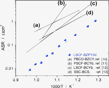 | ||
| Fig. 1 ASR vs. reciprocal temperature of LSCF-BZPY30 cathode in humidified (pH2O ≈ 0.03 atm) air, compared with literature data; PrBaCo2O5+δ-BaZr0.1Ce0.7Y0.2O3−δ (PBCO-BZCY, ref. 10), Pr0.58Sr0.4Co0.2 Fe0.8O3−δ-BaCe0.9Yb0.1O3−δ (PSCF-BCYb, ref. 11), La0.6Sr0.4Co0.2Fe0.8O3−δ-BaCe0.9Yb0.1O3−δ (LSCF-BCYb, ref. 12), and Sm0.5Sr0.5CoO3−δ and BaCe0.8Sm0.2O3−δ (SSC-BCS, ref. 13). | ||
LSCF-BZPY30 composite cathode showed ASR values of 0.02, 0.16, and 1.1 Ω cm2 at 700, 600, and 500 °C, respectively. Fig. 1 also compares the ASR of the developed cathode with literature data,10–13 showing the significantly improved performance of the LSCF-BZPY30 cathode.
For protonic SOFCs, the use of a composite cathode made by a mixed proton/electronic and a mixed oxygen-ion/electronic conducting materials results in an extended active area for the electrochemical reactions. As shown in Fig. 2, the H+ ions can transfer from the electrolyte to the cathode, migrate through the bulk cathode, and finally react with the O2− ions created by dissociative oxygen adsorption and reduction at the cathode surface. Therefore, for the developed composite cathode, the cathodic reaction leading to the formation of water is extended over a wide surface area including the electrode/electrolyte interface, the BZPY30 surface, and the LSCF-BZPY30 interface. The extended active area and the high porosity achieved by using nanometric particle powders prepared by combustion method can explain the low ASR obtained for the LSCF-BZPY30 cathode.
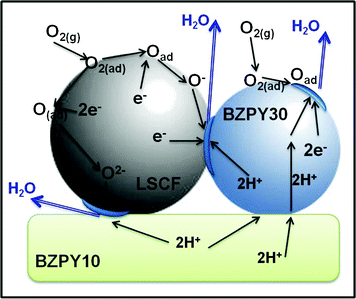 | ||
| Fig. 2 Schematic of the possible reaction pathways for the LSCF-BZPY30 cathode. The active area where the cathode reaction can take place is highlighted in blue. | ||
Anode/electrolyte bi-layers were fabricated by co-pressing and co-firing. The sinteractive anode made of NiO-BZY powders (1![[thin space (1/6-em)]](https://www.rsc.org/images/entities/char_2009.gif) :
:![[thin space (1/6-em)]](https://www.rsc.org/images/entities/char_2009.gif) 1 wt% ratio) produced by the novel combustion method was used.8 To further enhance the anode porosity, 20 wt.% of starch was added as a pore former. As electrolyte material, BZPY10 was used since it showed high proton conductivity, good chemical stability and sinterability.7 The co-pressed anode/electrolyte bi-layers were co-fired at 1400 °C for 6 h, and then the LSCF-BZPY30 cathode was brush painted on the electrolyte surface and co-fired at 1000 °C for 3 h.
1 wt% ratio) produced by the novel combustion method was used.8 To further enhance the anode porosity, 20 wt.% of starch was added as a pore former. As electrolyte material, BZPY10 was used since it showed high proton conductivity, good chemical stability and sinterability.7 The co-pressed anode/electrolyte bi-layers were co-fired at 1400 °C for 6 h, and then the LSCF-BZPY30 cathode was brush painted on the electrolyte surface and co-fired at 1000 °C for 3 h.
Fig. 3a shows the FE-SEM micrograph of the fractured cross section of the complete cell after the co-firing process. The anode, rather dense, was approximately 0.5 mm thick, while the thickness of the BZPY10 electrolyte layer was about 12 μm. The electrolyte was dense, with an average distance between grains of about 1.1 μm, as shown by the high magnification SEM micrograph in Fig. 3b. The same grain size was obtained sintering BZPY10 pellets at 1600 °C for 8 h.7 In this case, the sinteractive anode favors the BZPY10 sintering and thus allows the complete densification of the thin membrane, achieving also large grain size, at a temperature 200 °C lower than that needed to sinter the pellets. Despite the anode being rather dense, as mentioned above, after the co-firing process, the in situreduction of NiO to Ni before fuel cell operation allows creating a suitable porosity for gas transport.8Fig. 3c shows a high magnification FE-SEM micrograph of the composite cathode. A fine microstructure with relatively small average particle size was achieved, providing thus a large specific surface area that also accounts for the low ASR measured.
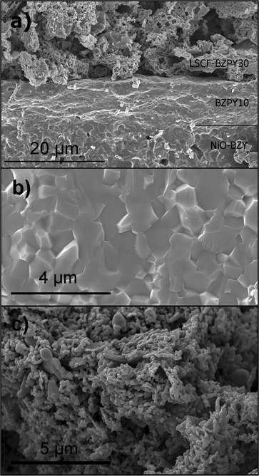 | ||
| Fig. 3 Cross-section FE-SEM micrograph of the NiO-BZY/BZPY10/LSCF-BZPY30 complete cell (a); high magnification micrographs of the BZPY10 electrolyte (b), and of the LSCF-BZPY30 cathode (c). | ||
Fig. 4a and 4b show the IV and power density curves, respectively, acquired at 600 °C with flowing hydrogen at the anode side and using ambient air at the cathode side. An open circuit voltage (OCV) of 0.97 V and a maximum power density output of 163 mW cm−2 were measured at 600 °C, being one of the best results reported in the literature for protonic SOFCs based on chemically stable electrolytes. For sake of comparison, Fig. 4a and 4b also report the IV and power density curves obtained for two other protonic SOFCs fabricated previously using the same sinteractive anode of the present work, but with different electrolyte and cathode materials,8 and using the BZPY10 electrolyte, but with different electrodes.7 The comparison of the IV curves evidences the reduced polarization losses at the low and high current densities, as well as the reduced slope at intermediate current density, which accounts for smaller ohmic losses of the present cell with respect to those reported in ref. 7 and 8.
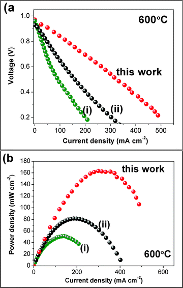 | ||
| Fig. 4 Power density curves measured for the NiO-BZY/BZPY10/LSCF-BZPY30 cell at 600 °C (a). For sake of comparison, the power density curves reported in ref. 8 (i) and ref. 7 (ii) are reported. | ||
Table 1 reports the peak power density output (PPD) reported in the literature for SOFCs based on chemically stable proton conducting electrolytes. In the present study, the combination of the tailored electrodes and the BZPY10 electrolyte accounts for one of the largest power output density achieved so far.
| Electrolyte | Anode | Cathode | PPD | RΩ | Rp | Ref. |
|---|---|---|---|---|---|---|
| a NiO-BZY prepared by combustion. b BZY electrolyte fabricated by pulsed laser deposition. c BaCe0.7Ta0.1Y0.2O3-δ. d BaCe0.7Nb0.1Sm0.2O3-δ. e La0.99Ca0.01NbO4. f La0.5Ce0.5O1.7. g La0.995Sr0.005NbO4. | ||||||
| BZPY10 | Ni-BZY a | LSCF-BZPY30 | 163 | 0.53 | 0.53 | This work |
| BZPY10 | Ni-BZY | LSCF-BZPY10 | 81 | 1.33 | 1.3 | 7 |
| BZY | Ni-BZY a | LSCF-BZPY10 | 51 | 1.12 | 3.18 | [8 |
| BZY b | Ni-BZY | LSCF-BaCe0.9Yb0.1O3-δ | 110 | 1.8 | 0.56 | 14 |
| BZY/In | Ni-BZY | PrBaCo2O3-δ -BZPY10 | 169 | 0.88 | 0.26 | 15 |
| BZY | Ni-BZY | Ba0.5Sr0.5Co0.8Fe0.2O3-δ | 23 | — | — | 16 |
| BZY | Ni-BCZY | Sm0.5Sr0.5CoO3-δ-Ce0.8Sm0.2O2 | 70 | 1.4 | 1.3 | 17 |
| BZY-Li | Ni-BZY | LSCF-BZY | 26 | — | — | 18 |
| BCTY c | Ni- BCTYc | La0.7Sr0.3FeO3-δ-BCZY | 84 | 1.08 | 0.95 | 19 |
| BCNSd | Ni- BCNSd | Nd0.7Sr0.3MnO3-δ | 75 | 1.1 | 1.2 | 20 |
| LCN e | Ni-LDC f | (La0.8Sr0.2)0.9MnO3-δ–LDCg | 65 (800 °C) | 2.35 (800 °C) | 0.69 (800 °C) | 21 |
Fig. 5 shows the complex impedance plane plot acquired in situ under open circuit voltage. The cell ohmic resistance (RΩ), calculated from the high frequency intercept with the real axis, was 0.53 Ω cm2 and a similar value was also obtained for the polarization resistance (Rp), taken as the difference between the high frequency and the low frequency intercepts with the real axis. Considering the RΩ values reported in Table 1, a significant reduction in the ohmic resistance was achieved in the present study. This is due to the high density, large grain size, and good conductivity of the BZPY10 electrolyte. The polarization resistance was also significantly lower than most of the values reported in Table 1, accounting for the good LSCF-BZPY30 cathode performance.
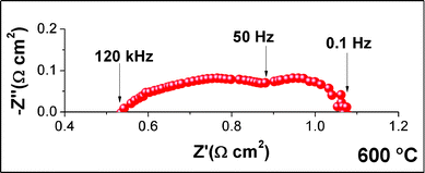 | ||
| Fig. 5 Complex-impedance plane plot of the single NiO-BZY/BZPY10/LSCF-BZPY30 cell measured at 600 °C under open circuit voltage. | ||
Among protonic SOFCs, the cell made by the NiO-BZY sinteractive anode/BZPY10 electrolyte/BZPY30-LSCF cathode showed very promising results in terms of power density output, achieving 163 mW cm−2 at 600 °C. This result was achieved combining a good proton conductor electrolyte together with tailored electrode materials and microstructures. EIS analysis showed that ohmic and polarization resistances mostly equally contributed to the total cell area specific resistance. A further reduction in the total cell resistance might be achieved enhancing the porosity of the anode, which is quite dense as observed by SEM analysis, without impairing its ability to promote electrolyte sintering. Moreover, SEM analysis evidences some area of poor adhesion between the cathode and the electrolyte, which should be avoided to improve the performance.
Acknowledgements
This work was financially supported in part by the World Premier International Research Center Initiative of MEXT, Japan.References
- E. Fabbri, D. Pergolesi and E. Traversa, Chem. Soc. Rev., 2010, 39, 4355 RSC.
- L. Malavasi, C. A. J. Fisher and M. S. Islam, Chem. Soc. Rev., 2010, 39, 4370 RSC.
- D. Pergolesi, E. Fabbri, S. Sanna, A. D'Epifanio, E. Di Bartolomeo, A. Tebano, G. Balestrino, S. Licoccia and E. Traversa, Nature Mater., 2010, 9, 846 CrossRef CAS.
- S. M. Haile, G. Staneff and K. H. Ryu, J. Mater. Sci., 2001, 36, 1149 CrossRef CAS.
- E. Fabbri, D. Pergolesi, S. Licoccia and E. Traversa, Solid State Ionics, 2010, 181, 1043 CrossRef CAS.
- Y. Yamazaki, C. Yang and S. M. Haile, Scripta Mater., 2011, 65, 102 CrossRef CAS.
- E. Fabbri, L. Bi, H. Tanaka, D. Pergolesi and E. Traversa, Adv. Funct. Mater., 2011, 21, 158 CrossRef CAS.
- L. Bi, E. Fabbri, Z. Q. Sun and E. Traversa, Energy Environ. Sci., 2011, 4, 1352 RSC.
- E. Fabbri, I. Markus, L. Bi, D. Pergolesi and E. Traversa, Solid State Ionics, accepted. Search PubMed.
- F. Zhao, S. Wang, K. Brinkman and F. Chen, J. Power Sources, 2010, 195, 5468 CrossRef CAS.
- V. B. Vert, C. Solís and J. M. Serra, Fuel Cells, 2011, 11, 81 CrossRef CAS.
- E. Fabbri, S. Licoccia, E. Traversa and E. D. Wachsman, Fuel Cells, 2009, 9, 128 CrossRef CAS.
- T. Wu, R. Peng and C. Xia, Solid State Ionics, 2008, 179, 1505 CrossRef CAS.
- D. Pergolesi, E. Fabbri and E. Traversa, Electrochem. Commun., 2010, 12, 977 CrossRef CAS.
- L. Bi, E. Fabbri, Z. Q. Sun and E. Traversa, Energy Environ. Sci., 2011, 4(2), 409 RSC.
- Y. Guo, Y. Lin, R. Ran and Z. Shao, J. Power Sources, 2009, 193, 400 CrossRef CAS.
- W. Sun, L. Yan, Z. Shi, Z. Zhu and W. Liu, J. Power Sources, 2010, 195, 4727 CrossRef CAS.
- Z. Q. Sun, E. Fabbri, L. Bi and E. Traversa, Phys. Chem. Chem. Phys., 2011, 13, 7692 RSC.
- L. Bi, S. Zhang, S. Fang, Z. Tao, R. Peng and W. Liu, Electrochem. Commun., 2008, 10, 1598 CrossRef CAS.
- K. Xie, R. Yan, X. Chen, D. Dong, S. Wang, X. Liu and G. Meng, J. Alloys Compd., 2009, 472, 551 CrossRef CAS.
- B. Lin, S. Wang, X. Liu and G. Meng, J. Alloys Compd., 2009, 478, 355 CrossRef CAS.
| This journal is © The Royal Society of Chemistry 2011 |
