Optimization strategy for fuel-cell catalysts based on electronic effects†
Li
Xiao
,
Bing
Huang
,
Lin
Zhuang
* and
Juntao
Lu
College of Chemistry and Molecular Sciences, Hubei Key Lab of Electrochemical Power Sources, Wuhan University, Wuhan, 430072, China. E-mail: lzhuang@whu.edu.cn
First published on 13th October 2011
Abstract
Understanding the structure–activity relationship (SAR) is essential for catalyst innovation. Here we report a methodology to unravel the elusive SAR of fuel-cell catalysts by individually studying the electronic structure–surface reactivity (ES–SR) relationship and the surface reactivity–catalytic activity (SR–CA) relationship. In the light of this methodology, we demonstrate a strategy for optimizing fuel-cell alloy catalysts, featuring the rational manipulation of the surface reactivity through electronic effects. For Pt-alloy cathode catalysts with Pt-rich surface, such as Pt-segregated Pt-Ni alloy, the key is to weaken the surface reactivity through the strain effect; optimum catalytic activity toward the oxygen reduction reaction (ORR) is predicted to be achieved on a contraction in Pt lattice by 1.9%. For Pd-based anode catalysts, on the other hand, the ligand effect will play an important role, and enhancing the surface reactivity by alloying with Cu can boost the catalytic activity toward the formic-acid oxidation reaction (FAOR) by orders in magnitude.
The power density of fuel cells is fundamentally determined by the performance of electrode catalysts. Despite decades of effort, the art of making efficient catalysts for fuel-cell reactions has not been fully mastered by researchers. Although accumulated experience does provide some instructive clues for catalytic promotion, a systematic understanding of the structure–activity relationship (SAR) of fuel-cell catalysts has hitherto not been established. For instance, it has been known that alloying Pt with 3d metals can effectively improve its catalytic activity (CA) toward the oxygen reduction reaction (ORR) because of the weakening in the surface reactivity (SR) of Pt,1–5 but why incorporating more reactive 3d metals can lower the surface reactivity of Pt and how to rationally optimize the surface reactivity are still open questions. Also intriguing is the unique behavior of Pd: being inferior to Pt for most fuel-cell reactions, Pd turns out to be the best catalyst for the formic-acid oxidation reaction (FAOR).6–8
The key to unravel the elusive structure–activity relationship (SAR) of fuel-cell catalysts relies not only on the understanding of the relationship between the surface reactivity (SR) and the electronic structure (ES) of catalyst, but also on the mechanistic insight into the target reaction, in particular the nature of its rate-determining step. In other words, the so-called SAR of catalyst is actually determined by both the catalyst itself and the target reaction, it may thus be divided into two parts: the electronic structure–surface reactivity (ES–SR) relationship and the surface reactivity–catalytic activity (SR–CA) relationship (Fig. 1). The former can be studied irrespective to a particular reaction; and the latter can be experimentally established by observing the response of the catalytic activity toward the target reaction upon modifying the surface reactivity of catalyst. The advantage of this methodology for the structure–activity relationship study is that the electronic structure–surface reactivity (ES–SR) relationship is now attainable through combined computational and experimental studies.9–12 Specifically, modern density-functional theory (DFT) calculations can provide insights into the electronic structure of a defined surface,13–16 and the predicted surface reactivity can be further examined by surface-sensitive detections.17–20 Once the electronic structure–surface reactivity (ES–SR) relationship is understood, it is then possible to rationally manipulate the surface reactivity through electronic effects, so as to observe the surface reactivity–catalytic activity (SR–CA) dependence (Fig. 1).
 | ||
| Fig. 1 The bridging role of the surface reactivity (SR) between the electronic structure (ES) and the catalytic activity (CA). On the one side, the surface reactivity can be regarded as an intrinsic property of a catalyst determined by its electronic structure. On the other side, the catalytic activity of a catalyst is an interactive property depending both on its surface reactivity and on the nature of the rate-determining step of the target reaction. | ||
The most commonly employed method to modify the electronic structure and surface reactivity of metal catalysts is alloying. Upon incorporating a foreign element into the host metal, two major electronic effects will be induced: the strain effect and the ligand effect.21–25 The former is caused by the size mismatch between the host and the foreign atoms, leading to a compression or expansion in the host lattice; while the latter refers to the change in the chemical surrounding (ligand) of the host atom, arising from the particular chemical nature of the alloying component. These two electronic effects are difficult to be distinguished by experiments, but can be disentangled by theoretical computations. In DFT calculations, solids with arbitrary lattice constant can be virtually created, thus pure ligand effects can be studied by using virtual alloys without lattice strain; while pure strain effects can be mimicked on a pure metal with its lattice deliberately strained to a given degree. With this technique, the electronic structure–surface reactivity (ES–SR) relationship of Pt3Ni(111), the thus-found best catalyst for the ORR,3 is unravelled as follows.
As shown in Fig. 2a, the surface reactivity, gauged by the calculated oxygen binding energy,26 is strongly dependent on the atomic configuration of the catalyst surface. The surface reactivity of pristine Pt3Ni(111) is higher than that of Pt(111); but when the Pt segregation occurs at the topmost layer (inset of Fig. 2a), a typical surface structure of this type of alloy catalyst,1–5 the surface reactivity becomes lower than that of Pt(111). Such a dramatic change in the surface reactivity stems literally from the distinction in the electronic structure. As illustrated in Fig. 2b, the electronic structures of the pristine Pt3Ni(111) and the Pt-segregated one differ to a large extend; both the greater density-of-states at the Fermi level, DOS(EF), and the elevated d-band center (εd) of the pristine Pt3Ni(111) indicate that a much higher surface reactivity will result if the Ni atom stays at the topmost layer. More importantly, the Pt-segregated Pt3Ni(111), denoted as PtSPt3Ni(111), turns out to be almost equivalent, in terms of surface reactivity, to a virtual Pt(111) with the Pt lattice contracted to the same level as that of Pt3Ni (Fig. 2a), suggesting that, only when staying at the topmost layer, can the ligand effect of Ni be significant to the surface reactivity; otherwise the strain effect will dominate. Upon incorporating Ni atoms, the Pt lattice is more or less compressed and the enhanced overlap in the electron orbital of neighboring Pt atoms causes a widening in the d-band (Fig. 2b), as well as a decline in DOS(EF) and εd. All these changes in the electronic structure give rise to a decrease in the surface reactivity.
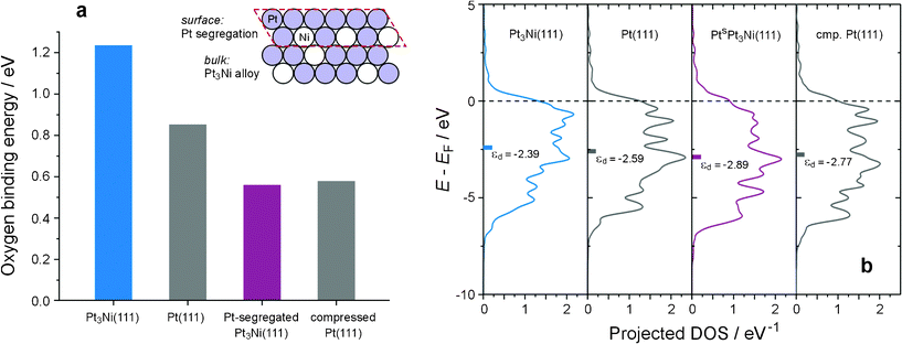 | ||
| Fig. 2 The electronic structure–surface reactivity (ES–SR) relationship of the Pt3Ni(111) system. (a) The dependence of surface reactivity, gauged by the oxygen binding energy,26 on the surface atomic structure. The surface reactivity of pristine Pt3Ni(111) is higher than that of Pt(111); but it decreases on Pt-segregated Pt3Ni(111) (Inset), akin to that on a virtual Pt(111) surface with the Pt lattice compressed to the same level as that of Pt3Ni. (b) Projected d density-of-states (DOS) of atoms at the topmost layer of Pt3Ni(111), Pt(111), Pt-segregated Pt3Ni(111) (denoted as PtsPt3Ni(111)), and virtual Pt(111) with compressed Pt lattice (cmp. Pt(111)). | ||
Although weakening the surface reactivity of Pt turns out to be responsible for the improvement of the catalytic activity toward the ORR, the surface reactivity of PtSPt3Ni(111) is not yet optimal. According to the surface reactivity–catalytic activity (SR–CA) model proposed by Nørskov and co-workers,2,5 the decline in the surface reactivity of PtSPt3Ni(111) is somewhat too much; and a modest reduction in the oxygen binding energy by about 0.2 eV, relative to that of Pt(111), would be the most appropriate (Fig. 3a). Now that the electronic structure–surface reactivity (ES–SR) relationship of this type of catalyst is understood, the guideline for catalyst optimization is clear: to control the contraction degree of the Pt lattice. As seen in Fig. 3b, upon compressing the Pt lattice, the surface reactivity decreases linearly; and a reduction of 0.2 eV in oxygen binding energy can be achieved with a relative Pt lattice of 0.981. In other words, 1.9% would be the best degree for the Pt lattice contraction, which can be realized by adjusting the alloying degree of PtSPtxNi alloy or analogs. Strasser and coworkers have also observed the strain effect in Pt-Cu alloy nanoparticles after leaching out the Cu component,1 but, probably due to additional effects caused by the highly-disordered and unpredictable morphology of the resulting Pt-skeleton structure, they did not conclude an optimal contraction degree of the Pt lattice. The theoretical prediction in Fig. 3b thus remains to be further verified in future studies.
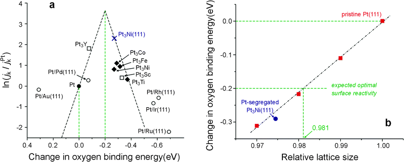 | ||
| Fig. 3 A guideline for optimizing Pt-segregated PtxNi alloy and analogs toward the ORR. (a) The reported surface reactivity-catalytic activity (SR-CA) relationship (reproduced from Fig. 1A in ref. 2 with permission from NPG) indicates a reduction of 0.2 eV in the oxygen binding energy,26 relative to that of Pt(111), may result in the best catalytic activity toward the ORR. (b) On the surface of Pt-segregated PtxNi alloy and analogs, whose surface reactivity is dominated by the strain effect, the oxygen binding energy decreases linearly upon compressing the Pt lattice; the expected optimal surface reactivity should then correspond to a contraction in the Pt lattice by 1.9%. | ||
Even without Pt segregation or deliberately de-alloying, 3d metals cannot remain stable under the operating condition of fuel-cell cathode and will be leached from the alloy surface.1,27 But such a surface depletion of the alloying component may not occur at the fuel-cell anode which is operated at low potentials, thus the ligand effect contributed by surface alloying atoms will mix with the strain effect. A typical example is the Cu–Pd–Au system (inset of Fig. 4a). On the one hand, because the metallic radius sequence is Cu < Pd < Au, alloying Pd with Cu or Au will reduce or increase the surface reactivity of Pd, respectively, according to the strain effect. On the other hand, the reactivity sequence is Cu > Pd > Au (Fig. 4a), thus alloying with Cu or Au will enhance or decrease the surface reactivity of Pd, respectively, because of the ligand effect. The DFT calculations shown in Fig. 4a have taken into account both effects and indicate the ligand effect to be dominant in this case. This prediction has been verified experimentally by the Pd-Cu and Pd-Au alloy electrodes prepared in this work28,29 (Fig. S1–S3†). The electrochemical behaviors of these electrodes have sensitively reflected the change in the surface reactivity of Pd upon alloying (Fig. S4†). In particular, the well-developed stripping peak of surface oxides turns out to be a good indicator of the surface reactivity. As demonstrated in Fig. 4b, when alloying with Cu, the enhanced surface reactivity makes the stripping of surface oxides more difficult, resulting in a negative shift in the peak potential (E[O]); when alloying with Au, a reverse move in the stripping peak is observed as expected. The approximately linear response of E[O] on the alloying degree (Fig. S5†) manifests the success in deliberate control on the surface reactivity, which enables the subsequent surface reactivity–catalytic activity (SR–CA) relationship study of Pd-alloy catalysts toward anodic reactions of interest.
 | ||
Fig. 4 Computational and experimental results of surface-reactivity tuning for Pd. (a) Calculated oxygen binding energy of Cu(111), Pd(111), Au(111), and their alloy surfaces. Inset: The Cu–Pd–Au system in the periodic table, with data showing the regular change in their metallic radius and electronegativity. (b) I–V curves of the surface-oxide stripping over PdxM (M![[double bond, length as m-dash]](https://www.rsc.org/images/entities/char_e001.gif) Cu or Au) alloys. Data were recorded in 0.1 mol L−1HClO4 solution at a potential scan rate of 50 mV/s. The current has been normalized to the stripping charge so as to underscore the regular change in the peak potential upon alloying Cu or Au (also see Fig. S4 and S5†), manifesting the deliberate control on the surface reactivity (SR). Cu or Au) alloys. Data were recorded in 0.1 mol L−1HClO4 solution at a potential scan rate of 50 mV/s. The current has been normalized to the stripping charge so as to underscore the regular change in the peak potential upon alloying Cu or Au (also see Fig. S4 and S5†), manifesting the deliberate control on the surface reactivity (SR). | ||
As mentioned at the beginning of this article, Pd is distinguished by its superior catalytic activity toward the FAOR. The formic acid can be completely oxidized over Pd through a non-poisoning reaction pathway at low overpotenitals30 (Fig. S6†). To unravel the origin of such a catalytic particularity, the dependence of the catalytic activity on the surface reactivity of Pd was studied, with intriguing results demonstrated in Fig. 5. Even though Pd is the known best catalyst for the FAOR, alloying with Cu can still boost the catalytic activity further to a tremendous extent. The I–V curve moves robustly to the negative potential upon incorporating Cu (Fig. 5a); and the half-wave potential (E1/2) of the I–V curve, a gauge of the catalytic activity, changes almost linearly with the E[O]-indexed surface reactivity31 (Fig. 5b), indicating an exponential increase in the reaction rate. The positive correlation between the E1/2 and the E[O] validates the use of oxygen affinity as an adequate descriptor for the surface reactivity in this case, and also implies that the FAOR may take place in a direct oxidation pathway through the bridge-bonded formate (*OCHO*) intermediate (Fig. S7†), which is in agreement with the in situFTIR observation.30 Thus a strategy for optimizing Pd-based catalysts toward the FAOR is to increase the surface reactivity, by making use of the ligand effect, so as to enhance the dehydrogenation process of HCOOH until the reaction mechanism changes.32
![The surface reactivity-catalytic activity (SR-CA) relationship of Pd toward the FAOR. (a) Typical I–V curves of the FAOR over PdxM (MCu or Au) alloys. Data were recorded using a rotating disk electrode at a rotation rate of 900 rpm and a potential scan rate of 2 mV s−1 in 0.1 mol L−1HClO4 solution containing 10−3 mol L−1formic acid. (b) The approximately linear dependence of the catalytic activity (CA) toward FAOR, gauged by the half-wave potential (E1/2) of the I–V curve, on the surface reactivity (SR) of PdxM, indexed by the peak potential of the surface-oxide stripping curve (E[O], see Fig. 4b and S5).](/image/article/2011/RA/c1ra00378j/c1ra00378j-f5.gif) | ||
| Fig. 5 The surface reactivity-catalytic activity (SR-CA) relationship of Pd toward the FAOR. (a) Typical I–V curves of the FAOR over PdxM (MCu or Au) alloys. Data were recorded using a rotating disk electrode at a rotation rate of 900 rpm and a potential scan rate of 2 mV s−1 in 0.1 mol L−1HClO4 solution containing 10−3 mol L−1formic acid. (b) The approximately linear dependence of the catalytic activity (CA) toward FAOR, gauged by the half-wave potential (E1/2) of the I–V curve, on the surface reactivity (SR) of PdxM, indexed by the peak potential of the surface-oxide stripping curve (E[O], see Fig. 4b and S5). | ||
The above-demonstrated strategy for optimizing fuel-cell catalysts through electronic effects bears fundamental and technological significance; not only has the methodology of separating the electronic structure-surface reactivity and surface reactivity–catalytic activity relationships been proven an effective approach to unravel the structure–activity relationship of catalysts, but the insights provided by combined computational and experimental studies have also rationalized the design strategy for better catalysts.
Methods
DFT calculations were performed using the DACAPO code (http://www.camd.dtu.dk/software.aspx) with calculating parameters chosen for both the convergence in energy and relatively less computational effort. The Kohn–Sham one-electron valence states were expanded in a basis of plane waves with kinetic energies up to 25 Ry, and ionic cores were described by ultrasoft pseudopotentials. The exchange–correlation potential and energy were described self-consistently using the GGA-PW91 functional. For the calculations of surface electronic structure and adsorption, a 2×2 surface unit cell was used to construct a four-layer metal slab and repeated in super cell geometry with successive slabs separated by a vacuum region equivalent to 6 metal layers. Adsorption was allowed on only one of the two exposed surfaces, and the dipole correction was made at the z-direction between two neighboring slabs. The adsorbate layer and the top two layers of the slab were allowed to relax. The surface Brillouin zone was sampled at 6×6 special Chadi-Cohen k-points. Spin polarization is included in all Ni-involved calculations.Electrochemical co-depositions of Pd and Cu (or Au) onto a glassy carbon (GC) or Au rotating disk electrode (RDE) (5 mm in diameter, Pine Research Instruments) were performed at a rotation rate of 1600 rpm in a deaerated 0.1 mol L−1NaCl solution containing precursors, the concentrations of which were on the order of 10−5 mol L−1 with a given ratio of Pd/M (MCu, Au) (Fig. S1†). A graphite paper was used as the counter electrode, and a Ag/AgCl (0.1 M NaCl) or a saturated calomel electrode (SCE) was served as the reference electrode. A diffusion-limiting potential, −0.4 V vs.SCE, was used for co-deposition so that the alloying degree can be adjusted based on the nominal ratio of precursors.28 The potentiostat was a CHI660 electrochemical station. The RDE system consisted of a PINE rotator and an interchangeable electrode (E6 Series). All chemicals were of at least analytical grade, and solutions were prepared using deionized water (18 MΩ cm). All experiments were conducted at room temperature.
The metal-deposited disk electrode was taken out from the RDE and subjected to SEM observations (Fig. S3†) using a field emission scanning electron microscope (KECK FE-SEM LEO-1550). To better image surface details, a low accelerating voltage of 3 kV was applied. Grazing-incidence X-ray Diffraction (GID) was employed to characterize the surface alloying degree of Pd alloys (Fig. S2†). Experiments were performed on a home-made six-circle kappa diffractometer at the G2 Station of the Cornell High Energy Synchrotron Source (CHESS). The X-ray beam energy was 9.4 keV. The beam size was 2 mm horizontal by 200 μm vertical. The flux at the center of rotation was about 1011photons/s mm2. The scanning range of the two-theta angle was from 30° to 40°, covering the Pd(111) and Pd(200) diffraction peaks.
The as-prepared Pd-alloy electrode was cleaned repeatedly via rotating in deionized water prior to the following tests. Cyclic voltammetry was carried out in deaerated 0.1 M HClO4 solution (Fig. S4†). A sheet of graphite paper, rather than metals such as Pt, was used as the counter electrode so as to exclude any possibility of metal contamination of the Pd-alloy electrode during experiments. The reference electrode was a reversible hydrogen electrode (RHE) in the same solution. The FAOR evaluation was carried out under the same conditions as CV measurements in a 0.1 mol L−1HClO4 solution containing 10−3 mol L−1formic acid. The low concentration of formic acid was deliberately chosen as so to record the diffusion-limiting current for the calculation of reaction electron number and to use the half-wave potential (E1/2) for the catalytic activity comparison (Fig. S6†). The I–V curves were recorded by sweeping the potential from the open circuit potential to 0.4 V (vs. RHE) at 2 mV/s.
Acknowledgements
This work was financially supported under the Natural Science Foundation of China (20933004, 20773096, and J0730426), the Fundamental Research Funds for the Central Universities (203275662, 203275672), and the National Hi-Tech R&D Program (2007AA05Z142). The authors are grateful to Dr Yi Liu and Prof. Héctor Abruña at Cornell University for their assistance in surface characterizations of the Pd-alloy electrodes.References
- P. Strasser et al., Lattice-strain control of the activity in dealloyed core–shell fuel cell catalysts, Nat. Chem., 2010, 2, 454–460 CrossRef CAS.
- J. Greeley et al., Alloys of platinum and early transition metals as oxygen reduction electrocatalysts, Nat. Chem., 2009, 1, 552–556 CrossRef CAS.
- V. Stamenkovic et al., Improved oxygen reduction activity on Pt3Ni(111) via increased surface site availability, Science, 2007, 315, 493–497 CrossRef CAS.
- V. Stamenkovic et al., Trends in electrocatalysis on extended and nanoscale Pt-bimetallic alloy surfaces, Nat. Mater., 2007, 6, 241–247 CrossRef CAS.
- V. Stamenkovic et al., Changing the activity of electroctalysts for oxygen reduction by tuning the surface electronic structure, Angew. Chem., Int. Ed., 2006, 45, 2897–2901 CrossRef CAS.
- V. Mazumder and S. Sun, Oleylamine-mediated synthesis of Pd nanoparticles for catalytic formic acid oxidation, J. Am. Chem. Soc., 2009, 131, 4588–4589 CrossRef CAS.
- E. Antolini, Palladium in fuel cell catalysis, Energy Environ. Sci., 2009, 2, 915–931 RSC.
- S. Ha, R. Larsen, Y. Zhu and R. I. Masel, Direct formic acid fuel cells with 600 mA cm-2 at 0.4 V and 22 °C, Fuel Cells, 2004, 4, 337–343 CrossRef CAS.
- W. E. Kaden, T. Wu, W. A. Kunkel and S. L. Anderson, Electronic structure controls reactivity of size-selected Pd clusters adsorbed on TiO2 surfaces, Science, 2009, 326, 826–829 CrossRef CAS.
- T. Bligaard, Linear energy relations and the computational design of selective hydrogenation/dehydrogenation catalysts, Angew. Chem., Int. Ed., 2009, 48, 9782–9784 Search PubMed.
- E. Nikolla, J. Schwank and S. Linic, Measuring and relating the electronic structures of nonmodel supported catalytic materials to their performance, J. Am. Chem. Soc., 2009, 131, 2747–2754 CrossRef CAS.
- P. Glatzel, J. Singh, K. O. Kvashnina and J. A. van Bokhoven, In situ characterization of the 5d density of states of Pt nanoparticles upon adsorption of CO, J. Am. Chem. Soc., 2010, 132, 2555–2557 CrossRef CAS.
- W. Kohn, Nobel Lecture: Electronic structure of matter—wave functions and density functional, Rev. Mod. Phys., 1999, 71, 1253–1266 CrossRef CAS.
- J. K. Nørskov, T. Bligaard, J. Rossmeisl and C. H. Christensen, Towards the computational design of solid catalysts, Nat. Chem., 2009, 1, 37–46 CrossRef CAS.
- J. Greeley, J. K. Nørskov and M. Mavrikakis, Electronic structure and catalysis on metal surfaces, Annu. Rev. Phys. Chem., 2002, 53, 319–348 CrossRef CAS.
- B. Hammer and J. K. Nørskov, Why gold is the noblest of all the metals, Nature, 1995, 376, 238–240 CrossRef.
- A. Weismann et al., Seeing the Fermi surface in real space by nanoscale electron focusing, Science, 2009, 323, 1190–1193 CrossRef CAS.
- C. A. Lucas et al., Temperature-induced ordering of metal/adsorbate structures at electrochemical interfaces, J. Am. Chem. Soc., 2009, 131, 7654–7661 Search PubMed.
- K. J. Andersson, F. Calle-Vallejo, J. Rossmeisl and I. Chorkendorff, Adsorption-driven surface segregation of the less reactive alloy component, J. Am. Chem. Soc., 2009, 131, 2404–2407 CrossRef CAS.
- G. A. Somorjai, H. Frei and J. Y. Park, Advancing the frontiers in nanocatalysis, biointerfaces, and renewable energy conversion by innovations of surface techniques, J. Am. Chem. Soc., 2009, 131, 16589–16605 CrossRef CAS.
- A. Groβ, Reactivity of bimetallic systems studied from first principles, Top. Catal., 2006, 37, 29–39 CrossRef CAS.
- J. R. Kitchin, J. K. Nørskov, M. A. Barteau and J. G. Chen, Role of strain and ligand effects in the modification of the electronic and chemical properties of bimetallic surfaces, Phys. Rev. Lett., 2004, 93, 156801 CrossRef CAS.
- A. Schlapka, M. Lischka, A. Groβ, U. Käsberger and P. Jakob, Surface strain versus substrate interaction in heteroepitaxial metal layers: Pt on Ru(0001), Phys. Rev. Lett., 2003, 91, 016101 CrossRef CAS.
- Y. Gauthier et al., Adsorption sites and ligand effect for co on an alloy surface: a direct view, Phys. Rev. Lett., 2001, 87, 036103 CrossRef CAS.
- M. Mavrikakis, B. Hammer and J. K. Nørskov, Effect of strain on the reactivity of metal surfaces, Phys. Rev. Lett., 1998, 81, 2819–2822 CrossRef.
- The oxygen binding energy (OBE) was obtained from DFT calculations and defined as the change in the total energy (E) of the adsorption system: OBE = EM + 1/2EO2 – EM-O, where M denotes the metal substrate. A positive OBE indicates that the dissociative adsorption of O2 is spontaneous. Note another convention was used in the literature, in which adsorption energy was defined as the opposite value of binding energy.
- K. J. J. Mayrhofer, K. Hartl, V. Juhart and M. Arenz, Degradation of carbon-supported Pt bimetallic nanoparticles by surface segregation, J. Am. Chem. Soc., 2009, 131, 16348–16385 CrossRef CAS.
- Pd-Cu and Pd-Au alloys were prepared using electrochemical co-depositions under diffusion-limiting potentials (Fig. S1†), such that the alloying degree can be adjusted based on the nominal ratio of precursors. This method has been reported by F. Maroun, F. Ozanam, O. M. Magnussen and R. J Behm, The role of atomic ensembles in the reactivity of bimetallic electrocatalysts, Science, 2001, 293, 1811–1184 Search PubMed.
- Pd-alloy electrodes thus prepared were characterized using grazing-incidence X-ray diffraction (GID) and electron-scanning microscopy (SEM). The GID measurements found clear shifts in the X-ray diffraction peaks upon alloying (Fig. S2†), ascertaining that the alloying degree is very close to the nominal ratio of precursors. The SEM measurements showed that the electrodes share the same morphology (Fig. S3†), precluding the possible morphology effects on the SR.
- H. Miyake, T. Okada, G. Samjeskeb and M. Osawa, Formic acid electrooxidation on Pd in acidic solutions studied by surface–enhanced infrared absorption spectroscopy, Phys. Chem. Chem. Phys., 2008, 10, 3662–3669 RSC.
- According to our DFT calculations and Osawa's ATR-FTIR experiments,30 the intermediate in formic acid oxidation is the bridge-bonded formate over Pd surface, thus we use the oxygen affinity as an indicator of the surface reactivity of Pd alloys for the discussion of FAOR catalysis.
- A decline in the catalytic activity was observed when the alloying degree of Cu was higher than 30 at%, which may indicate a change in the reaction mechanism, most probably due to the involvement of the poisoning reaction pathway.
Footnote |
| † Electronic Supplementary Information (ESI) available. See DOI: 10.1039/c1ra00378j/ |
| This journal is © The Royal Society of Chemistry 2011 |