DOI:
10.1039/C1RA00373A
(Paper)
RSC Adv., 2011,
1, 1349-1357
Nitrogen-doped graphene nanosheet-supported non-precious iron nitride nanoparticles as an efficient electrocatalyst for oxygen reduction†
Received
27th June 2011
, Accepted 10th August 2011
First published on 7th October 2011
Abstract
Nitrogen-doped graphene-supported carbon-containing iron nitride (FeCN/NG) was synthesized by the chemical impregnation of iron and nitrogen-containing precursors in the presence of ammonia under thermal treatment. The resultant graphene-based material acted as an electrode with a much higher electrocatalytic activity in the catalysis via a 4-electron pathway in fuel cells. The results of X-ray diffraction, scanning electron microscopy, Fourier transform infrared and X-ray photoelectron spectroscopy indicated that graphite oxide was successfully reduced to nitrogen-doped graphene. X-Ray absorption spectroscopy further confirmed that carbon was incorporated into iron nitride, demonstrating that Fe–N–C catalytic active sites may be responsible for the oxygen reduction reaction. To the best of our knowledge, this is the first report of the combination of N-doped graphene with non-precious metal for oxygen reduction in fuel cells, and may open up a new possibility for preparing graphene-based nanoassemblies for intensive applications.
Introduction
In recent decades, most scientific activity in the search for outstanding catalysts has been driven primarily by the demands of fuel cells, which are regarded as important devices in the future, because of major improvements over gasoline combustion and reduction in CO2 emissions. Noble ultrafine pieces of metal have long been regarded as important electrocatalysts in fuel cells. Such metals include Pt, Pd and their alloys (Pt-based and Pd-based).1–4 Although these materials perform well in the electrochemical reaction of fuels to generate energy, their drawbacks include their susceptibility to time-dependent drift, CO deactivation and cost and lack of abundance in nature, all of which limit any mass market for commercially developed fuel cells.5–8 Recently, research has been conducting into reducing their use by using substitutes for the noble metal. Non-precious metal nitrides are possible candidates due to their low cost and acceptable catalytic activity, comparable to that of Pt in the oxygen reduction reaction (ORR).9–13 In 1964, cobalt phthalocyanine was observed to catalyze the ORR. Since then extensive research has been carried out to develop practical non-precious metal catalysts (NPMCs).14 Most investigations have attributed the catalysis of oxygen to Me–N4 or Me–N2 centers of metallomacrocycles and C-containing distribution of MNxCy sites.15,16 N4-coordination, being similar to that in N4-macrocycles, is indicative of catalysts that are produced at lower temperatures (T ≤ 550 °C).17 On the other hand, catalysts that are formed at higher temperature (700 °C ≤ T ≤ 900 °C) exhibit N2-coordination (N2-macrocycles), in which two nitrogen atoms are included in each graphene sheet.18 These metal active centers maintained nitrogen-coordinated structures and bonded to the carbon support, providing the enhanced stability in this pyrolized system.
Another key issue that contributes to the high electrocatalytic activity is related to the nature of the carbon support, which can assist in both dispersing the metal catalysts and dominating electron transfer, facilitating mass transport kinetics at the electrode surface. The discovery of graphene began a new era of 2-dimensional (2D) fundamental science and technology. Graphene, a single-atom-thick sheet of an sp2-hybridized carbon network, has attracted intense fascination since its discovery in 2004.19 Regardless of types for 0D buckyballs, 1D nanotubes and 3D graphite, they all consist of similar carbon atom networks, whose parent structure is graphene. Owing to disclosure of their enormous surface area (theoretical surface area of 2630 m2 g−1), excellent electric conductivity (theoretical conductivity of 1250 S m−1) and mechanical strength, graphene can be adopted in many fields such as electronic devices,20,21 energy storage,22,23hydrogen storage24,25 and biosensors26,27, having established many of their electronic and optical properties during their discovery by scientists. Early studies of graphene-based electrocatalysts demonstrated their promising potential applications in fuel cells.28,29 One method of fabricating efficient electrocatalysts is nitrogen doping,30–32 which not only enhances the conductivity of graphene, but also creates carbon atoms around nitrogen atoms as active sites.33,34 The incorporation of nitrogen atoms into the matrix of carbon results in electron withdrawing from the carbon because of the higher electronegativity of nitrogen.35 The N-induced charge-transfer from neighboring carbon atoms can reduce the barrier of the ORR potential, weakening the O–O bonding on the surface of the catalysts and releasing the ORR obstruction at the electrodes.31 Furthermore, nitrogen plays a role as an n-type carbon dopant that induces the formation of disordered carbon nanostructures and donates electrons to the carbon, dominating the ORR procedure.36 An investigation of the CVD-deposited N–graphene sheets for ORR at the cathode revealed a much greater electrocatalytic activity, indicating that metal-free N-containing graphene is an efficient catalyst.37 However, ORR yields two possible products, H2O and H2O2via 4-electron and 2-electron pathways, respectively, and only one of those carbon atoms that are directly bonded to nitrogen (CxNy catalytically active sites) may enable a 2-electron reduction to hydrogen peroxide,32,38 originating from the weak associative adsorption of O2 to form OOH− intermediate.39 This undesired product may cause serious etching damage to the proton exchange membrane (PEM) in a fuel cell, resulting in a decreased duration. Thus, numerous challenges must be overcome.
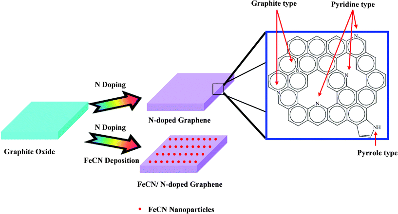
Drawing inspiration from the above studies, this work uses a combination of iron nitride and N-doped graphene. Herein N-doped graphene and FeCN (carbon-containing iron nitride, described in the latter analysis) nanoparticles that are supported on N-doped graphene are synthesized by using graphite oxides (GO) that are mixed with Fe and N precursors in an atmosphere of ammonia (NH3). 1,10-Phenanthroline, an N-containing ligand that has aromatic rings, can be adsorbed to the surface of graphite oxide through a π–π stacking interaction and can harvest Fe by using its lone-pair electrons on nitrogen atoms, revealing a bifunctional ability. Hence, a cooperative π–π superimposition between graphite oxide and a planar aromatic molecule utilized here is provided with explosion to grow graphene-based nanoassemblies. X-Ray photoelectron spectroscopy reveals important features of the chemical environment of nitrogen that is incorporated into the graphene layers as pyridinic, pyrrolic and graphitic type species.40–42X-Ray absorption spectroscopy (XAS) yields information about the graphitization of carbon networks and the coordination of incorporated nitrogen with Fe under different modification. Cyclic voltammetry (CV) exhibits the electrochemical performances, revealing that conductivity can be increased and a close 4-electron reaction can proceed via suitable decoration. The whole procedure for the preparation of graphene-based electrocatalysts and the XPS characteristics of N species are shown in Scheme 1.
Experimental
Synthesis of graphite oxide
The preparation procedure for graphite oxide (GO) followed that reported in the literature.43 2.0 g graphite (G) powder (20 μm, Timrex®) and 1.0 g sodium nitrate (NaNO3, 99%, Acros) were added into 140 mL concentrated sulfuric acid (H2SO4, 95–97%, Sigma-Aldrich) and stirred for 2 h under ice-cooling in a hood. Then, 6.0 g potassium permanganate (KMnO4, 99%, Acros) was slowly added under the same treatment again. Subsequently, 500 mL deionized (DI) water was gradually poured into the reacted slurry for 2 h with agitation. Then, 30 mL hydrogen peroxide (H2O2, 34.5–36.5%, Sigma-Aldrich) was added, and the dispersed slurry turned from dark brown to bright yellow which was accompanied by bubbling. The top of the solution was decanted after the bubbling stopped and then 0.1 M hydrochloric acid (HCl, 37%, Sigma-Aldrich) was added to a total volume of 500 mL. This process was repeated several times until barium sulfate (BaSO4) was no longer formed upon the addition of barium chloride (BaCl2, 99.995%, Merck) in order to precipitate out the slightly sulfonated functional groups. The slurry was then further rinsed with DI water until the pH of the washing solution was almost neutral (6.5). The remaining solid was dried at 80 °C and ground to a fine powder.
Chemicals and materials
Iron acetate (Fe(CH3COO)2, Fe content: 29.5%, Alfa Aesar), 1,10-phenanthroline monohydrate (C12H8N2·H2O, 99.8%, Riedel-deHaen), graphite oxide (GO) and sulfuric acid (H2SO4, 95–97%, Fluka) were purchased from commercial chemicals. GO was prepared in our laboratory. All chemicals were used without further purification. The water used in the experiment was of reagent grade and was produced by using a Milli-Q SP ultrapure-water purification system from Nihon Millipore Ltd., Tokyo, Japan.
Fabrication method of graphene-based electrocatalysts
GO powder was treated directly in an NH3 atmosphere at 800 °C for 2 h to obtain N-doped graphene (NG). The metal-containing catalyst was impregnated by mixing iron acetate and 1,10-phenanthroline with the desired Fe proportion of 4.1 wt%. They were mixed in a solution of 10 mL of ethanol to form an N-coordinated Fe complex. The complex turned red during sonication for 0.5 h and was then immediately dried in an atmosphere of air at approximately 70 °C for 12 h. The dried powder was ball-milled for 3 h at 400 rpm, yielding a well-dispersed powder. Eventually, the obtained sample was sintered under the same condition with NG to obtain FeCN nanoparticles that were supported on N-doped graphene (FeCN/NG).
Characterization of electrocatalysts
The crystallographic structures of graphene-based electrocatalysts were obtained by using an X-ray powder diffractor (XRD, X'Pert PRO diffractometer) under Cu Kα radiation (λ = 1.5418 Å). The morphologies of the samples were determined by using a field emission scanning electron microscope (FE-SEM, JEOL JSM-6700F). The chemical environments of the target samples were measured using a Fourier transform infrared spectrometer (FTIR, Varian 640-IR). The chemical states of the samples were characterized by using an X-ray photoelectron spectrometer (XPS, PHI Quantera) under Al Kα radiation (λ = 8.3406 Å). The vibrational properties of these samples were analyzed by using appropriate equipment (Raman, Ibin-Yvon LabRam) with an exciting source (632.8 nm He-Ne laser).
Electrochemical measurements
A module of a three-electrode system was constructed to make electrochemical measurements. A glassy carbon electrode (GC electrode, 5 mm in diameter, PINE: AFE3T050GC) was prepared as the working electrode and a platinum plate was used as the counter electrode. The surface of the glassy carbon (GC) electrode (5 mm in diameter) was polished by using alumina powder (0.05 μm). Then, powdered catalyst was uniformly dispersed in deionized watervia an ultrasonic shock to obtain the catalyst ink for subsequent preparation. Then, 20 μL of the catalyst ink (catalyst loadings of 200 μg cm−2) was applied onto the pre-polished GC electrode. After it had been dried in air at 30 °C, the surface of the electrode was covered with 20 μL of a 0.05% Nafion solution (Du Pont DE2020) that was diluted by using isopropyl alcohol and dried in air at room temperature, forming a thin proton exchange film. The cyclic voltammograms (CVs) were obtained under N2 atmosphere in 0.5 M sulfuric acid electrolyte at a scanning rate of 20 mV s−1 over 20 cycles (activation for steady CV) to evaluate the electrochemical properties between 0 and 1 V. The catalytic activity, determined by ORR, was explored in the solution of an oxygen-rich 0.5 M sulfuric acid electrolyte that was equipped by using a rotating disk electrode (RDE) that revolved at 1600 rpm. All current–voltage (I–V) curve measurements were made using a potentiostat (Eco Chemie AUTOLAB) and GPES (General Purpose Electrochemical System) software. The rotating ring disk electrode (RRDE) was employed to detect the number of transferred electrons and the H2O2 yield by using the bi-potentialstatic electrochemical analyzer (CHI 760D, USA). These measurements were made in 0.5 M sulfuric acid electrolyte at a scan rate of 10 mV s−1, purged with O2 gas. All of the tests were conducted at room temperature and all potentials were recorded versus the potential of the reversible hydrogen electrode (RHE).
XAS data analysis
The Fe K-edge (7112 eV) and C K-edge (284.2 eV) XAS spectra were obtained in transmission mode at the BL17C1 and in fluorescence mode at the BL20A stations at the National Synchrotron Radiation Research Center (NSRRC), Taiwan. The BL17C1 beamline moved 2 mrad of radiation from the tip to the left wing of the horizontal radiation fan of the superconducting-wavelength-shifter (SWLS) X-ray source. The energy resolution (ΔE/E), estimated from the rocking curves of the double crystal Si (111) monochromator, was (1.7–3.0) × 10−4 and the energy ranged from 4 to 15 keV. The ion chamber was filled with a mixture of gaseous nitrogen and helium and was used to measure the incident beam intensity (I0). Meanwhile, a mixture of argon and nitrogen gases was introduced to measure the transmitted beam intensity (It). The BL20A beamline carried out at a 6 m high-energy spherical grating monochromator (HSGM). In front of a microchannel plate (MCP) detector with a dual set of MCPs that was mounted an electrically isolated grid and the energy ranged from 0.11 to 1.5 keV. The photon flux of the incident beam (I0) was monitored by using a nickel mesh (80% transmission) that was situated at the rear of the exit of the monochromator. All of the XAS experiments were carried out at room temperature.
Extended X-ray absorption fine structure (EXAFS) data analysis
The backscattering amplitude and phase shift functions for particular atom pairs were calculated ab initio by using the FEFF7 code. EXAFS analyses were performed by using an analytical package called “REX2000” coded by Rigaku. The raw X-ray absorption data modified using standard procedures, including pre-edge and post-edge background subtraction, normalization with respect to edge height, Fourier transformation and nonlinear least-squares curve fitting.44 The Fourier transformed (FT) k3-weighted EXAFS spectra ranged from 3 to 13.2, and was used to estimate the contribution of each bonding pair to the FT peak. The experimental Fourier-filtered spectra were obtained by performing an inverse FT with a Hanning window function with r between 0.83 and 2.85 Å. The value of the amplitude reduction factor (S02) value for iron was fixed at 0.88 to evaluate the structural parameters for each bond pairs. Structure-related parameters, including coordination number, interatomic distance, absorption energy shift and Debye–Waller factor were given to elucidate information about FeCN/NG electrocatalyst.
Results and discussion
Structural and morphological analyses viaXRD and SEM
As described in the previous section, graphite oxide was prepared by the chemical exfoliation of commercial graphite powder. Fig. 1 shows the XRD patterns of graphene-based samples. Chemical oxidation breaks the ordering of graphite layers by introducing a variety of functional groups (epoxide, carboxyl, etc.).45 The exfoliation of individual sheets is assisted by these functional groups, disrupting the interaction between layers and resulting in the loss of the ordered lattice structure in the sheets. This structural conversion increases the interplanar distance between the sheets, shifting the XRD peak to smaller angles (12°) in GO (ESI, Fig. S1†).46 After the doping of nitrogen using NH3, the XRD peak of the graphene phase in NG shows a shift to bigger angles (26°).47Graphite oxide is reduced to graphene because NH3 splits into N2 and H2 at high temperature.48 H2 serves as a reductant, causing a reduction of O-containing groups on the GO. Upon comparing with NG, FeCN/NG displays a Fe2N phase (JCPDS, file no. 89-3939) and the diffraction peaks centered at 37.58°, 40.82°and 42.94°correspond to (110), (002) and (![[1 with combining macron]](https://www.rsc.org/images/entities/char_0031_0304.gif) 1) reflections, respectively. The presence of an Fe2N phase demonstrates the formation of iron nitride that is dispersed on the N-doped graphene. The measured d-spacing at about 26°, ranging from the GO (7.59 Å), NG (3.36 Å) to the FeCN/NG (3.38 Å), may enhance the number of active sites. Further calculation of their average particle sizes are the 7.29 Å, 6.27 Å and 3.98 Å, for GO, NG and FeCN/NG respectively. Accordingly the theoretical thickness of graphene monolayer is 0.34 Å, their numbers of layers can be obtained as follows: GO 10, NG 18 and FeCN/NG 12, demonstrating an exfoliation from the graphite. Their different morphologies recorded by SEM are shown in Fig. 2. The image of GO describes rippled and fluffy sheets possibly owing to the introduction of O-containing functional groups with dimensions of several hundreds of nanometers to several micrometers (Fig. 2a). Single sheets are usually difficult to photograph with good contrast, but stacked ones can readily be imaged by using electron microscopy. The sheets of NG are slightly thicker than those of GO, demonstrating the removal of functional groups and a regenerative π–π stacking interaction by thermal annealing (Fig. 2b). After further deposition of iron nitride nanoparticles, their dispersion on the N-doped graphene sheets can be observed clearly (Fig. 2c). The morphologies of electrocatalysts influence their activity as determined by probing CV performance in subsequent analyses.
1) reflections, respectively. The presence of an Fe2N phase demonstrates the formation of iron nitride that is dispersed on the N-doped graphene. The measured d-spacing at about 26°, ranging from the GO (7.59 Å), NG (3.36 Å) to the FeCN/NG (3.38 Å), may enhance the number of active sites. Further calculation of their average particle sizes are the 7.29 Å, 6.27 Å and 3.98 Å, for GO, NG and FeCN/NG respectively. Accordingly the theoretical thickness of graphene monolayer is 0.34 Å, their numbers of layers can be obtained as follows: GO 10, NG 18 and FeCN/NG 12, demonstrating an exfoliation from the graphite. Their different morphologies recorded by SEM are shown in Fig. 2. The image of GO describes rippled and fluffy sheets possibly owing to the introduction of O-containing functional groups with dimensions of several hundreds of nanometers to several micrometers (Fig. 2a). Single sheets are usually difficult to photograph with good contrast, but stacked ones can readily be imaged by using electron microscopy. The sheets of NG are slightly thicker than those of GO, demonstrating the removal of functional groups and a regenerative π–π stacking interaction by thermal annealing (Fig. 2b). After further deposition of iron nitride nanoparticles, their dispersion on the N-doped graphene sheets can be observed clearly (Fig. 2c). The morphologies of electrocatalysts influence their activity as determined by probing CV performance in subsequent analyses.
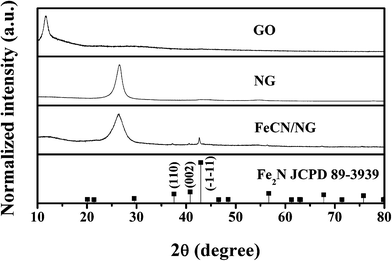 |
| | Fig. 1
XRD characterization of graphene-based electrocatalysts. | |
 |
| | Fig. 2
SEM images of graphene-based electrocatalysts: (a) GO, (b) NG and (c) FeCN/NG. | |
Chemical environment detection viaIR, XPS and Raman
To corroborate the loss of O-containing groups on the GO through N-doping, FTIR was performed (Fig. 3). The spectrum of GO illustrates features that correspond to C–O (νC–O at 1060 cm−1), C–O–C (νC–O–C at 1250 cm−1), C–OH (νC–OH at 1400 cm−1) and C![[double bond, length as m-dash]](https://www.rsc.org/images/entities/char_e001.gif) O in carboxylic acid and carbonyl moieties (νCO at 1720 cm−1).49,50 The peak close to 1600 cm−1 (CC) can be attributed to skeletal vibrations of unoxidized sp2 domains.51 However, the characteristic curve changes dramatically after transition to NG. The heat eliminates almost all O-containing groups and increases the intensity of the peaks associated with unoxidized graphitic domains, demonstrating an increase in graphitization as the stacked layers attract each other. A similar phenomenon in the presence of FeCN/NG demonstrates that thermal treatment can eliminate the barriers of repulsion of O-containing groups that are introduced to the graphite, indicating that GO is reduced to graphene nanosheets.47 To probe the effect of nitrogen doping, XPS measurements were made to investigate graphene-based samples. As can be seen in Fig. 4 (a), the XPS survey spectrum before and after nitrogen doping includes a predominant narrow graphitic C 1s peak at 284.2 eV, an N 1s peak at 400 eV, an O 1s peak at 540 eV, together with an Fe 2p peak at 706 eV over a wide range of energy (0 to 900 eV).37,52 It is obviously observed that the signal of N 1s appears after nitrogen doping. The stronger intensity of the FeCN/NG electrocatalyst indicates that addition of N from 1,10-phenanthroline also facilitates N content. Nevertheless, the oxygen content in exfoliated GO decreases remarkably after nitrogen doping, that is, this heat treatment eliminates the oxygen functionalities on GO, which corresponds to the observation in FTIR. Besides, the red arrow in Fig. 4 (a) points out the presence of Fe, demonstrating the encapsulation of Fe in FeCN/NG electrocatalyst. Fig. 4 (b) shows the fitted C 1s peak of GO, which consists of five components that arise from C–C (284.8 eV), C–OH/C–O/C–O–C (285.7 eV) and CO (287.2 eV).42,53 The additional component at 286.2 eV from NG and FeCN/NG is assigned to the CN bond.50 As revealed by the fitted curves, the constituents of oxygen functionalities decrease after nitrogen doping and the contribution of CN is distributed over the N-doped samples. These observations indicate considerable deoxygenation through the process of nitrogen doping. Moreover, the N 1s spectrum in Fig. 4 (c) is deconvoluted to elucidate three components originating from pyridine-like (399.04 eV), pyrrole-like (400.25 eV) and graphite-like (401.09 eV) nitrogen atoms within the graphene structure, all of which play certain roles in the ORR process (Scheme 1).39 It is preferentially believed that an O2 molecule adsorbs associatively at C sites on graphene-like zigzag edges, if a graphite-like N is situated nearby. This substitutional N makes nearby C atoms possess higher electronegativity owing to polarization and thereby facilitate the strong binding of O2 to the C atoms in the outermost layer.35 Therefore, the higher catalytic activity in the ORR is likely to be related to the presence of graphite-like N. Based on the fitting of the three components herein, the chemical state of graphite-like N is characteristic of higher activity toward ORR for the above statements. The intensity of graphite-like N for FeCN/NG is stronger than that for NG, directly suggesting a better validity of ORR catalysis. Furthermore, O2 molecule can also adsorb onto FeCN nanoparticles, enhancing the ORR activity further. Raman spectroscopy is a widely used approach for the recognition of carbon materials and in particular the detail of carbon–carbon bonds. Fig. S2 (ESI†) reveals that the G and the D bands both undergo significant variations upon amorphization of graphite from G to FeCN/NG transformation. The G line is attributed to the E2g mode of the in-plane sp2 domains, while the D line is characteristic of a breathing mode for κ-point A1g.54 Specifically the G band broadens obviously and shows a shift to a higher frequency as the intensity of the D band increases. Here, the frequencies of all samples for the D bands are almost the same (1328 cm−1), while those for the G bands are 1585 cm−1 in addition to graphite at 1572 cm−1, demonstrating a transition between graphite layers. On the other hand, the D/G intensity ratios from graphite to FeCN/NG are 0.2, 1.15, 1.28 and 1.47, respectively. This result indicates that an increased number of edge planes and the degree of disorder in the prepared graphene sheets.55 The increase in the D/G ratio from NG to FeCN/NG is caused by the addition of nitrogen, resulting in the presence of disorder located in carbon–carbon rings.
O in carboxylic acid and carbonyl moieties (νCO at 1720 cm−1).49,50 The peak close to 1600 cm−1 (CC) can be attributed to skeletal vibrations of unoxidized sp2 domains.51 However, the characteristic curve changes dramatically after transition to NG. The heat eliminates almost all O-containing groups and increases the intensity of the peaks associated with unoxidized graphitic domains, demonstrating an increase in graphitization as the stacked layers attract each other. A similar phenomenon in the presence of FeCN/NG demonstrates that thermal treatment can eliminate the barriers of repulsion of O-containing groups that are introduced to the graphite, indicating that GO is reduced to graphene nanosheets.47 To probe the effect of nitrogen doping, XPS measurements were made to investigate graphene-based samples. As can be seen in Fig. 4 (a), the XPS survey spectrum before and after nitrogen doping includes a predominant narrow graphitic C 1s peak at 284.2 eV, an N 1s peak at 400 eV, an O 1s peak at 540 eV, together with an Fe 2p peak at 706 eV over a wide range of energy (0 to 900 eV).37,52 It is obviously observed that the signal of N 1s appears after nitrogen doping. The stronger intensity of the FeCN/NG electrocatalyst indicates that addition of N from 1,10-phenanthroline also facilitates N content. Nevertheless, the oxygen content in exfoliated GO decreases remarkably after nitrogen doping, that is, this heat treatment eliminates the oxygen functionalities on GO, which corresponds to the observation in FTIR. Besides, the red arrow in Fig. 4 (a) points out the presence of Fe, demonstrating the encapsulation of Fe in FeCN/NG electrocatalyst. Fig. 4 (b) shows the fitted C 1s peak of GO, which consists of five components that arise from C–C (284.8 eV), C–OH/C–O/C–O–C (285.7 eV) and CO (287.2 eV).42,53 The additional component at 286.2 eV from NG and FeCN/NG is assigned to the CN bond.50 As revealed by the fitted curves, the constituents of oxygen functionalities decrease after nitrogen doping and the contribution of CN is distributed over the N-doped samples. These observations indicate considerable deoxygenation through the process of nitrogen doping. Moreover, the N 1s spectrum in Fig. 4 (c) is deconvoluted to elucidate three components originating from pyridine-like (399.04 eV), pyrrole-like (400.25 eV) and graphite-like (401.09 eV) nitrogen atoms within the graphene structure, all of which play certain roles in the ORR process (Scheme 1).39 It is preferentially believed that an O2 molecule adsorbs associatively at C sites on graphene-like zigzag edges, if a graphite-like N is situated nearby. This substitutional N makes nearby C atoms possess higher electronegativity owing to polarization and thereby facilitate the strong binding of O2 to the C atoms in the outermost layer.35 Therefore, the higher catalytic activity in the ORR is likely to be related to the presence of graphite-like N. Based on the fitting of the three components herein, the chemical state of graphite-like N is characteristic of higher activity toward ORR for the above statements. The intensity of graphite-like N for FeCN/NG is stronger than that for NG, directly suggesting a better validity of ORR catalysis. Furthermore, O2 molecule can also adsorb onto FeCN nanoparticles, enhancing the ORR activity further. Raman spectroscopy is a widely used approach for the recognition of carbon materials and in particular the detail of carbon–carbon bonds. Fig. S2 (ESI†) reveals that the G and the D bands both undergo significant variations upon amorphization of graphite from G to FeCN/NG transformation. The G line is attributed to the E2g mode of the in-plane sp2 domains, while the D line is characteristic of a breathing mode for κ-point A1g.54 Specifically the G band broadens obviously and shows a shift to a higher frequency as the intensity of the D band increases. Here, the frequencies of all samples for the D bands are almost the same (1328 cm−1), while those for the G bands are 1585 cm−1 in addition to graphite at 1572 cm−1, demonstrating a transition between graphite layers. On the other hand, the D/G intensity ratios from graphite to FeCN/NG are 0.2, 1.15, 1.28 and 1.47, respectively. This result indicates that an increased number of edge planes and the degree of disorder in the prepared graphene sheets.55 The increase in the D/G ratio from NG to FeCN/NG is caused by the addition of nitrogen, resulting in the presence of disorder located in carbon–carbon rings.
 |
| | Fig. 4
XPS surveys of graphene-based samples. (a) Full range, (b) fitted C 1s and (c) N 1s. | |
Structural analysis viaXAS
To confirm the electronic states and the bonds in a series of graphene-based samples, XAS analyses were carried out. Since XAS is delicate to the atomic bonding environment and can probe even tiny changes in it, it is a highly effective approach for analyzing the electronic states and bonding atoms.56 The C 1s X-ray absorption near edge spectroscopy (XANES) spectrum displayed in Fig. 5 (a) demonstrates the transformations on the graphene layers by graphitization upon doping with N. The π* states (285 to 289 eV) comprise graphitic rings (π*ring) and CO functional groups (π*CO), resulting in the transitions of 1s to π*.57 On the other hand, the σ* states (289 to 294 eV) are associated with the same species, but they belong to σ* transitions (σ*ring and σ*CO).57 Peaks C1 and C2 at approximately 286 and 292 eV are caused by C–C π* (ring) and C–C σ* (ring) excitations respectively.57,58 However, there is a trend that an increase of C1 and a decrease of C2, revealing the dominance of stronger π–π network. Further changes can be significantly observed within the C3 peak at about 290 eV, corresponding to carbon atoms that are attached to oxygen atoms.59 The detected decrease in intensity of this characteristic confirms the weakening of the oxygen functionalities. To elucidate the Fe-coordinated environment, an XAS of the Fe K-edge was conducted to obtain relative information. Fig. 5 (b) compares the normalized XANES spectrum of the FeCN/NG electrocatalyst with those of standard materials. The curve shown for the electrocatalyst is located between those of iron foil and iron acetate (7110 to 7125 eV) consistent with the oxidative valence of Fe in the Fe2N phase. The white line that is centered at approximately 7130 eV reveals the local electronic state and its intensity between signals from iron foil and iron acetate, indicating a similar trend with the above observations. The inset presents the EXAFS spectrum of the FeCN/NG electrocatalyst, listing the information in Table 1 by fitting its curve. The number for the degrees of freedom (Nf) is formulated by using the following equation: Nf = 2ΔkΔr/π + 2 ≈ 15.1, where Δk expresses the effective k-range of the data and Δr is the R-range of the data to be modified (as described in the part of the experimental section for the Hanning window). The fitting parameter (Np) is 12, which is lower than Nf, indicating a reliable result to satisfy the minimal requirements of the IXS standard.60 The Fe–N interatomic bond distance (1.94 Å) of the FeCN/NG electrocatalyst is consistent with that of the standard Fe2N, and representation of a Fe–N2 active center (coordination number: 2.1) is in agreement with the reported studies.15,16,18 However, the Fe–Fe interatomic bond distance (2.70 Å) is slightly lower than that in Fe2N, indirectly confirming the presence of the other Fe species. It was reported that transition metals such as Fe, Co and Ni could bind to carbon supports via an anchoring effect, and heat treatment facilitated the formation of carbide species (MexC).61 Furthermore, the presence of C incorporation (Fe–C interatomic bond) has been detected in the PANI–Fe–C electrocatalyst.62 Therefore, FexC species may be formed in this process by sintering with carbon. The EXAFS fitting parameter is consistent with the Fe–C bond length (2.07 Å) of the FeCN/NG electrocatalyst, which is close to that of reported Fe3C (2.08 Å) and 2.66 Å. In addition, the Fe–Fe interatomic bond length (2.70 Å) of FeCN/NG is located between that of Fe2N (2.72 Å) and Fe3C (2.66 Å), demonstrating a mixed phase. Accordingly, FeCN nanoparticles (C-containing iron nitride) are indeed attached to the sheets of N-doped graphene and the distribution of FeNxCy sites may also be responsible for ORR catalysis.16
 |
| | Fig. 5
XAS analyses of graphene-based electrocatalysts. (a) XANES of C K-edge. (b) XANES of Fe K-edge for FeCN/NG electrocatalyst. Inset shows its corresponding EXAFS curve. | |
Table 1
Fe K-edge EXAFS structural parameters of FeCN/NG electrocatalyst
| Sample |
Path |
R (Å) |
CN |
σ
2 (× 10−3 Å2) |
ΔE (eV) |
|
FeCN/NG |
Fe–Fe |
2.70(1) |
4.7(1) |
10.4(1) |
−9.9(4) |
| |
Fe–N |
1.94(2) |
2.1(1) |
1.2(2) |
−6.7(6) |
| |
Fe–C |
2.07(1) |
1.1(3) |
11.4(4) |
8.4(1) |
Electrochemical performance via CV
To evaluate the electrocatalytic activities of graphene-based samples toward ORR, the CV approach was used to study the performance. As displayed in Fig. 6 (a), there is an increase of the capacitance from GO to FeCN/NG, indicating the increasing dominance of the electrical conductivity and the faster transfer of charges.63 The high catalyst surface area and the presence of graphitic edges makes the carbon materials highly capacitive,64 contributing to the high capacitance and the possible high ORR activity. However, the GO material has a lower conductivity owing to the lack of an extended π-conjugated orbital system, and thus the electric conductivity can be viewed as an indicator to examine the extent for reduction of graphene.49 Consequently, the majority of O-containing functional groups are removed in our products after nitrogen doping. Furthermore, modification of FeCN nanoparticles on the surface of NG leads to a bigger enhancement of electric conductivity as compared with that of NG alone. Furthermore, the well-developed redox peaks at around 0.66 V indicate a correlation between the change in the oxidative state of the Fe species in the electrocatalyst and the relative features of reversible CV potential for the FeCN/NG catalyst.13Fig. 6 (b) plots ORR polarization curves obtained with and without nitrogen doping, which reveal the modification of FeCN nanoparticles. Comparing these three catalysts indicates that NG outperforms GO in ORR, but FeCN/NG has the highest catalytic activity (steady-state catalytic current density at 0.05 V, GO: −0.18, NG: −0.60 and FeCN/NG: −3.53 mA cm−2). The better performance can be attributed to the formation of active centers for graphite-like N positions and FeCN nanoparticles. Nitrogen doping reportedly introduces disorder in the stacked graphene layers and the formed defects may act as anchoring sites for attachments to metal species.65,66 The improved activity may also be caused by the bonding of the carbon-catalyst binding and an increase of electrical conductivity.67 On the other hand, the measured dissolution value of Fe ion for FeCN/NG is 2.75 × 10⁻⁵ wt%, so the Fe ion is almost not washed away in this catalyst, maintaining the catalytic activity. To even obtain quantitatively the number of transferred electrons (n) of the ORR catalysis, the so-called Koutecky–Levich test was measured at various rates of rotation of the electrode.68 In this approach, the reciprocal of the plateau current (ID−1) is plotted as a function versus the reciprocal rotating rate (ω−1) and the n merit is evaluated from the slope. The RDE current–potential curves at various rotating speeds for the FeCN/NG electrocatalyst are shown in Fig. 6c, demonstrating the high steady-state catalytic current density at high rotation due to a large increase in oxygen concentration. Comparing the experimental line of the FeCN/NG electrocatalyst with the theoretical lines for the ORR pathways with n = 2 and 4 electrons yielded an n value that is approximately 3.91 (Fig. 6d). This calculated number is extremely close to the theoretical 4-electron transferred process of the H2O product, suggesting that the 2-electron transferred process of the H2O2 product could not prefer involving in the ORR of this sample. Besides, the optimization of RDE ink formulations has been adjusted because of efficient active sites.69,70 The loading amount of the catalyst is lowered and the distribution of the active sites are sparse, promoting the undesirable diffusion of H2O2 product and 2-electron transport. To confirm in detail the H2O2 yield and the number of transferred electrons of the FeCN/NG electrocatalyst, RRDE was performed. H2O2 that is produced at the disk electrode is detected by the ring electrode. The n value is obtained from the ratio of the ring current (IR) to the disk current (ID). The number of transferred electrons and H2O2 yield can be recognized by using the formulas: n = 4 − 2(IR/N × ID) and H2O2% = 100(IR/(N × ID))71,72. The transferred electrons (approximately 3.93) obtained from Fig. S3 (ESI†) approaches that obtained from the aforementioned Koutecky–Levich plot. Furthermore, the generation of H2O2 is also small, indicating a highly efficient catalysis for ORR. These electrochemical measurements elucidate the improved ORR activity and the 4-electron pathway of the formation of H2O by catalyzed ORR.
 |
| | Fig. 6 CV measured curves of graphene-based electrocatalysts. (a) CV measurements under an N2-saturated condition in 0.5 M sulfuric acid electrolyte at a scan rate of 20 mV s−1. (b) ORR measurements under an O2-saturated condition in 0.5 M sulfuric acid electrolyte at a scan rate of 10 mV s−1. (c) Current–potential curves of the ORR measurement in an O2-saturated condition in 0.5 M sulfuric acid electrolyte at a scan rate of 10 mV s−1 for FeCN/NG electrocatalyst at various rates of rotation. (d) Koutecky–Levich plots at various rotation rates. | |
Conclusions
In summary, graphene-based electrocatalysts with incorporated N were developed. They can be readily treated to form a material in ORR. The key component is the introduction of FeCN nanoparticle supported on N-doped graphene. The FeCN/NG electrocatalyst shows a superb performance in ORR applied to fuel cells as compared with that of FeN and that of FeN/C. The steady-state catalytic current density at the FeCN/NG electrode is about 6 times higher than that at the NG electrode over a measured potential range. The number of transferred electrons indicate that H2O is a major product of this catalyzed ORR process, elucidating that the presence of harmful H2O2 is almost not produced. Comparing the ORR catalytic activity with commercial Pt electrocatalyst, there is even an enhancement, but this cost-effective electrocatalyst still has potential for fuel cell applications. We therefore anticipate that our findings will result in the advanced development in fabrication of low-cost and active graphene-based nanocomposites, and even brand new materials for use in fields beyond fuel cells.
Acknowledgements
The authors would like to thank Mr. Szu-Hsueh Lai and Prof. Chung-Hsuan Chen for the valuable measurements of Raman, Mr. Chin-Chang Shen for the precious measurements of XPS, Dr Jin-Ming Chen and Dr Jyh-Fu Lee for the treasurable XAS measurements and the National Science Council of the Republic of China, Taiwan (Contract No. NSC 97-2113-M-002-012-MY3) and the Industrial Technology Research Institute (ITRI), Taiwan for financially supporting this research.
References
- M. Winter and R. J. Brodd, Chem. Rev., 2004, 104, 4245–4270 CrossRef CAS.
- J. Kua and W. A. I. I. I. Goddard, J. Am. Chem. Soc., 1999, 121, 10928–10941 CrossRef CAS.
- Z. Liu, X. Y. Ling, B. Guo, L. Hong and J. Y. Lee, J. Power Sources, 2007, 167, 272–280 CrossRef CAS.
- M.-H. Shao, K. Sasaki and R. R. Adzic, J. Am. Chem. Soc., 2006, 128, 3526–3527 CrossRef CAS.
- W. M. Wang, Q. H. Huang and J.-Y. Liu, J. Catal., 2009, 266, 156–163 CrossRef CAS.
- M.-H. Shao, P. Liu and R. R. Azdic, J. Phys. Chem. B, 2007, 111, 6772–6775 CrossRef CAS.
- X. Yu and S. Ye, J. Power Sources, 2007, 172, 145–154 CrossRef CAS.
- K. Gong, F. Du, Z. Xia, M. Dustock and L. Dai, Science, 2009, 323, 760–764 CrossRef CAS.
- M. Lefèvre, E. Proietti, F. Jaouen and J.-P. Dodelet, Science, 2009, 324, 71–74 CrossRef.
- C. H. Choi, S. H. Park and S. I. Woo, Green Chem., 2011, 13, 406–412 RSC.
- K. Lee, L. Zhang, H. Lui, R. Hui, Z. Shi and J. J. Zhang, Electrochim. Acta, 2009, 54, 4704–4711 CrossRef CAS.
- A. A. Gewirth and M. S. Thorum, Inorg. Chem., 2010, 49, 3557–3566 CrossRef CAS.
- G. Wu, K. L. More, C. M. Johnston and P. Zelenay, Science, 2011, 332, 443–447 CrossRef CAS.
- R. Jasinski, Nature, 1964, 201, 1212 CrossRef CAS.
- U. I. Koslowski, I. Abs-Wurmbach, S. Fiechter and P. Bogdanoff, J. Phys. Chem. C, 2008, 112, 15356–15366 CAS.
- M. Lefèvre, J.-P. Dodelet and P. Bertrand, J. Phys. Chem. B, 2002, 106, 8705–8713 CrossRef.
- D. Scherson, A. A. Tanaka, S. L. Gupta, D. Tryk, C. Fierro, R. Holze and E. B. Yeager, Electrochim. Acta, 1986, 31, 1247–1258 CrossRef CAS.
- S. Gupta, D. Tryk, I. Bae, W. Aldred and E. B. Yeager, J. Appl. Electrochem., 1989, 19, 19–27 CrossRef CAS.
- K. S. Novoselov, A. K. Geim, S. V. Morozov, D. Jiang, Y. Zhang, S. V. Dubonos, I. V. Grigorieva and A. A. Firsov, Science, 2004, 306, 666–669 CrossRef CAS.
- D. A. Dikin, S. Stankovich, E. J. Zimney, R. D. Piner, G. H. B. Dommett, G. Evmenenko, S. T. Nguyen and R. S. Ruoff, Nature, 2007, 448, 457–460 CrossRef CAS.
- X. B. Meng, D. S. Geng, J. A. Liu, M. N. Banis, Y. Zhang, R. Y. Li and X. L. Sun, J. Phys. Chem. C, 2010, 114, 18330–18337 CAS.
- Y. Y. Shao, J. Wang, M. Engelhard, C. M. Wang and Y. H. Lin, J. Mater. Chem., 2010, 20, 743–748 RSC.
- E. Yoo, T. Okata, T. Akita, M. Kohyama, J. Nakamura and I. Honma, Nano Lett., 2009, 9, 2255–2259 CrossRef CAS.
- K. S. Subrahmanyam, S. R. C. Vivekchand, A. Govindaraj and C. N. R. Rao, J. Mater. Chem., 2008, 18, 1517–1523 RSC.
- G. Srinivas, Y. Zhu, R. Piner, N. Skipper, M. Ellerby and R. Ruoff, Carbon, 2010, 48, 630–635 CrossRef CAS.
- A. K. Geim and K. S. Novoselov, Nat. Mater., 2007, 6, 183–191 CrossRef CAS.
- L. H. Tang, Y. Wang, Y. M. Li, H. B. Feng, J. Lu and J. H. Li, Adv. Funct. Mater., 2009, 19, 2782–2789 CrossRef CAS.
- Y. Li, L. Tang and J. Li, Electrochem. Commun., 2009, 11, 846–849 CrossRef CAS.
- B. Seger and P. V. Kamat, J. Phys. Chem. C, 2009, 113, 7990–7995 CAS.
- Z. Chen, D. Higgins, H. S. Tao, R. S. Hsu and Z. W. Chen, J. Phys. Chem. C, 2009, 113, 21008–21013 CAS.
- K. P. Gong, F. Du, Z. H. Xia, M. Durstock and L. M. Dai, Science, 2009, 323, 760–764 CrossRef CAS.
- R. L. Liu, D. Q. Wu, X. L. Feng and K. Mullen, Angew. Chem., Int. Ed., 2010, 49, 2565–2569 CrossRef CAS.
- X. L. Li, H. L. Wang, J. T. Robinson, H. Sanchez, G. Diankov and H. J. Dai, J. Am. Chem. Soc., 2009, 131, 15939–15944 CrossRef CAS.
- K. R. Lee, K. U. Lee, J. W. Lee, B. T. Ahn and S. I. Woo, Electrochem. Commun., 2010, 12, 1052–1055 CrossRef CAS.
- Y. Sun, C. Li, Y. Xu, H. Bai, Z. Yao and G. Shi, Chem. Commun., 2010, 46, 4740–4742 RSC.
- G. Wu, D. Y. Li, C. S. Dai, D. L. Wang and N. Li, Langmuir, 2008, 24, 3566–3575 CrossRef CAS.
- L. Qu, Y. Liu, J.-B. Baek and L. Dai, ACS Nano, 2010, 4, 1321–1326 CrossRef CAS.
- R. A. Sidik, A. B. Anderson, N. P. Subramanian, S. P. Kumaraguru and B. N. Popov, J. Phys. Chem. B, 2006, 110, 1787–1793 CrossRef CAS.
- T. Ikeda, M. Boero, S.-F. Huang, K. Terakura, M. Oshima and J. Ozaki, J. Phys. Chem. C, 2008, 112, 14706–14709 CAS.
- A. G. Kudashov, A. V. Okotrub, L. G. Bulusheva, I. P. Asanov, Y. V. Shubin, N. F. Yudanov, L. I. Yudanova, V. S. Danilovich and O. G. Abrosimov, J. Phys. Chem. B, 2004, 108, 9048–9053 CrossRef CAS.
- A. Griffith, A. Glidle, G. Beamson and J. M. Cooper, J. Phys. Chem. B, 1997, 101, 2092–2100 CrossRef CAS.
- F. Su, Z. Tian, C. K. Poh, Z. Wang, S. H. Lim, Z. Liu and J. Lin, Chem. Mater., 2010, 22, 832–839 CrossRef CAS.
- W. S. J. Hummers and R. E. Offeman, J. Am. Chem. Soc., 1958, 80, 1339 CrossRef CAS.
-
Y. Iwasawa, X-ray Absorption Fine Structure for Catalysts and Surfaces, World Scientific, Singapore, 1996 Search PubMed.
- A. Lerf, H. Y. He, M. Forster and J. Klinowski, J. Phys. Chem. B, 1998, 102, 4477–4482 CrossRef CAS.
- H. C. Schniepp, J. L. Li, M. J. McAllister, H. Sai, M. Herrera-Alonso, D. H. Adamson, R. K. Prud'home, R. Car, D. A. Saville and I. A. Aksay, J. Phys. Chem. B, 2006, 110, 8535–8539 CrossRef CAS.
- L.-S. Zhang, X.-Q. Liang, W. G. Song and Z.-Y. Wu, Phys. Chem. Chem. Phys., 2010, 12, 12055–12059 RSC.
- N. Paterson, Y. Zhou, D. Dugwell and R. Kandiyoti, Energy Fuels, 2005, 19, 1016–1022 CrossRef CAS.
- Y. Si and E. T. Samulski, Nano Lett., 2008, 8, 1679–1682 CrossRef CAS.
- Z.-L. Hu, M. Aizawa, Z.-M. Wang, N. Yoshizawa and H. Hatori, Langmuir, 2010, 26, 6681–6688 CrossRef CAS.
- S. Stankovich, R. D. Piner, S. T. Nguyen and R. S. Ruoff, Carbon, 2006, 44, 3342–3347 CrossRef CAS.
- Y. P. Wang, Y. J. Wang, Q. L. Ren, L. Li, L. F. Jiao, D. W. Song, G. Liu, Y. Han and H. T. Yuan, Fuel Cells, 2010, 1, 132–138 Search PubMed.
- S. M. Lyth, Y. Nabae, S. Moriya, S. Kuroki, M. Kakimoto, J. Ozaki and S. Miyata, J. Phys. Chem. C, 2009, 113, 20148–20151 CAS.
- G. Wang, B. Wang, X. Wang, J. Park, S. Dou, H. Ahn and K. Kim, J. Mater. Chem., 2009, 19, 8378–8384 RSC.
- P. Lian, X. Zhu, S. Liang, Z. Li, W. Yang and H. Wang, Electrochim. Acta, 2010, 55, 3909–3914 CrossRef CAS.
-
(a) J. E. Penner-Hahn, Coord. Chem. Rev., 1999, 190–192, 1101–1123 CrossRef CAS;
(b) H. M. Chen, R.-S. Liu, K. Asakura, L.-Y. Jang and J.-F. Lee, J. Phys. Chem. C, 2007, 111, 18550–18557 CrossRef CAS;
(c) W.-R. Lee, M. G. Kim, J.-R. Choi, J.-I. Park, S. J. Ko, S. J. Oh and T. Cheon, J. Am. Chem. Soc., 2005, 127, 16090–16097 CrossRef CAS;
(d) S. Polarz, F. Neues, M. W. E. van den Berg, W. Grunert and L. Khodeir, J. Am. Chem. Soc., 2005, 127, 12028–12034 CrossRef CAS;
(e) M. P. Jensen, J. A. Dzielawa, P. Rickert and M. L. Dietz, J. Am. Chem. Soc., 2002, 124, 10664–10665 CrossRef CAS;
(f) H. M. Chen, C. F. Hsin, R.-S. Liu, J.-F. Lee and L.-Y. Jang, J. Phys. Chem. C, 2007, 111, 5909–5914 CrossRef CAS;
(g) H. M. Chen, C. F. Hsin, P. Y. Chen, R.-S. Liu, S.-F. Hu, C.-Y. Huang, J.-F. Lee and L.-Y. Jang, J. Am. Chem. Soc., 2009, 131, 15794–15801 CrossRef CAS.
- A. Kuznetsova, I. Popova, J. T. Yates, M. J. Bronikowski, C. B. Huffman, J. Liu, R. E. Smalley, H. H. Hwu and J. G. G. Chen, J. Am. Chem. Soc., 2001, 123, 10699–10704 CrossRef CAS.
- S. Banerjee, T. Hemraj-Benny, M. Balasubramanian, C. B. Huffman, D. A. Fischer, J. A. Misewich and S. S. Wong, Chem. Commun., 2004, 772–773 RSC.
- H. K. Jeong, H. J. Noh, J. Y. Kim, M. H. Jin, C. Y. Park and Y. H. Lee, Europhys. Lett., 2008, 82, 67004 CrossRef.
- Y.-C. Yeh, H. M. Chen, R.-S. Liu, K. Asakura, M.-Y. Lo, Y.-M. Peng, T.-S. Chan and J.-F. Lee, Chem. Mater., 2009, 21, 4030–4036 CrossRef CAS.
- N. Travitsky, T. Ripenbein, D. Golodnitsky, Y. Rosenberg, L. Burshtein and E. Peled, J. Power Sources, 2006, 161, 782–789 CrossRef CAS.
-
P. Zelenay, 2010Hydrogen Program Annual Merit Review and Peer Evaluation Meeting (http://www.hydrogen.energy.gov/pdfs/review10/fc005_zelenay_2010_o_web.pdf) Search PubMed.
- H.-K. Jeong, M. Jin, E. J. Ra, K. Y. Sheem, G. H. Han, S. Arepalli and Y. H. Lee, ACS Nano, 2010, 4, 1162–1166 CrossRef CAS.
- T. Kim, S. Lim, K. Kwon, S. H. Hong, W. Qiao, C. K. Rhee, S. H. Yoon and I. Mochida, Langmuir, 2006, 22, 9086–9088 CrossRef CAS.
- C. H. Wang, H. Y. Du, Y. T. Tsai, C. P. Chen, C. J. Huang, L. C. Chen, K. H. Chen and H. C. Shih, J. Power Sources, 2007, 171, 55–62 CrossRef CAS.
- R. L. Jia, C. Y. Wang and S. M. Wang, J. Mater. Sci., 2006, 41, 6881–6888 CrossRef CAS.
- R. I. Jafri, N. Rajalashmi and S. Ramaprabhu, J. Mater. Chem., 2010, 20, 7114–7117 RSC.
-
A. J. Bard and L. R. Faulkner, Electrochemical Methods: Fundamentals and Applications, 2nd ed., John Wiley & Sons, New York, 2001, Chapters 3 and 9 Search PubMed.
- A. Bonakdarpour, T. R. Dahn, R. T. Atanasoski, M. K. Debe and J. R. Dahn, Electrochem. Solid-State Lett., 2008, 11, B208–B211 CrossRef CAS.
- T. S. Olson, S. Pylypenko, J. E. Fulghum and P. Atanassov, J. Electrochem. Soc., 2010, 157, B54–B63 CrossRef CAS.
- C. W. B. Bezerra, L. Zhang, K. Lee, H. Liu, J. Zhang, Z. Shi, A. L. B. Marques, E. P. Marques, S. Wu and J. Zhang, Electrochim. Acta, 2008, 53, 7703–7710 CrossRef CAS.
- K. Lee, L. Zhang, H. Lui, R. Hui, Z. Shi and J. Zhang, Electrochim. Acta, 2009, 54, 4704–4711 CrossRef CAS.
Footnote |
| † Electronic supplementary information (ESI) available. See DOI: 10.1039/c1ra00373a |
|
| This journal is © The Royal Society of Chemistry 2011 |
Click here to see how this site uses Cookies. View our privacy policy here.