Microwave-assisted synthesis of TiO2-reduced graphene oxide composites for the photocatalytic reduction of Cr(VI)
Xinjuan
Liu
a,
Likun
Pan
*a,
Tian
Lv
a,
Guang
Zhu
a,
Ting
Lu
a,
Zhuo
Sun
a and
Changqing
Sun
b
aEngineering Research Center for Nanophotonics & Advanced Instrument, Ministry of Education, Department of Physics, East China Normal University, Shanghai, China. E-mail: lkpan@phy.ecnu.edu.cn; Fax: +86 21 62234321; Tel: +86 21 62234132
bSchool of Electrical and Electronic Engineering, Nanyang Technological University, Singapore, 639798, Singapore
First published on 19th September 2011
Abstract
TiO2-reduced graphene oxide (RGO) composites are successfully synthesized via the microwave-assisted reduction of graphite oxide in a TiO2 suspension using a microwave synthesis system. Their morphology, structure and photocatalytic performance in the reduction of Cr(VI) are characterized by scanning electron microscopy, transmission electron microscopy, atomic force microscopy, X-ray diffraction spectroscopy and UV-vis absorption spectrophotometer. The results show that in the composite the RGO nanosheets are densely decorated by TiO2 nanoparticles, which displays a good combination between RGO and TiO2. TiO2–RGO composites exhibit enhanced photocatalytic performance for the reduction of Cr(VI) with a maximum removal rate of 91% under UV light irradiation as compared with pure TiO2 (83%) and commercial TiO2 P25 (70%) due to the increased light absorption intensity and range as well as the reduction of electron-hole pair recombination in TiO2 with the introduction of RGO.
1. Introduction
As a rising star in the carbon family, graphene has attracted a great deal of attention in recent years owing to its excellent conductivity, superior chemical stability and high specific surface area.1–7 Chemical approaches, for the large-scale production of highly conducting graphene sheets, which speed up the application of graphene, have become reality. Investigations have been carried out to study the application of graphene in many fields, such as photocatalysis,8–11 energy storage,12–16 solar cells,17,18 transparent electrodes,19,20 and field emission.21Currently one attractive challenge is to combine these 2D carbon nanostructures with metal oxide to from hybrid materials with new functionalities.22–27 In the meantime, such an attachment of metal oxide particles onto graphene may also prevent the restacking and agglomeration of graphene sheets during the reduction process due to van der Waals interactions between them. Kamat et al.,28,29 Akhavan et al.,30,31 and Bell et al.32,33 fabricated TiO2-graphene composites by carrying out UV-assisted photocatalytic reduction of graphite oxide (GO) using TiO2 nanoparticles. Lambert et al.34 studied the synthesis of TiO2-graphene composites by hydrolysis of TiF4 in the presence of an aqueous dispersion of GO. Zou et al.35 synthesized TiO2–graphene composites by refluxing solution mixtures of GO and peroxotitanium complexes and the composites exhibited better charge separation capability than pure TiO2. Zhang et al.36 employed a sol–gel method using tetrabutyl titanate and GO as the starting materials to synthesize TiO2–graphene composites and found that both graphene content and calcination atmosphere could affect the photocatalytic H2 evolution activity of the composites. Guo et al.37 revealed that TiO2–graphene composites prepared by a sono-chemical method displayed better photocatalytic performance for the degradation of methylene blue compared to commercial pure TiO2. Fan et al.38 prepared TiO2 P25–graphene composites by three different methods, i.e., UV-assisted photo-reduction, chemical reduction using hydrazine and hydrothermal methods, which showed better photocatalytic performances in H2 evolution from methanol aqueous solution than alone P25. Shen et al.,39,40 Zhang et al.,41 Zhang et al.,42 and Zhou et al.43 carried out one-step hydrothermal methods to fabricate TiO2–graphene composites and demonstrated that the composites exhibited much higher photocatalytic activity in H2 evolution or organic degradation than pure TiO2. In the photocatalysis process, graphene can act as an excellent electron-acceptor/transport material to effectively facilitate the migration of photo-induced electrons and hinder the charge recombination in electron-transfer processes due to the electronic interaction between TiO2 and graphene, which enhances the photocatalytic performance of TiO2.37–43 Despite the above progress to date, as promising hybrid materials for photocatalysis, the exploration of TiO2–graphene composites still has a long way to go. Especially as an inexpensive, quick, versatile technique, microwave-assisted reactions are seldom employed to synthesize TiO2-reduced graphene oxide (RGO) hybrid composite materials for photocatalysis although such a method has been used successfully to fabricate RGO44,45 and TiO2.46,47
In this work, we successfully synthesize TiO2–RGO composites via microwave-assisted reduction of GO in TiO2 suspensions using a microwave system. Microwave irradiation can heat the reactants to high temperature in a short amount of time by transferring energy selectively to microwave absorbing polar solvents. Thus it can facilitate mass production in a short time frame with little energy cost48–50 and forms an intimate contact between TiO2 and RGO,51,52 which is crucial for the formation of electronic interactions and interelectron transfer at the interface.53TiO2–RGO composites exhibit enhanced photocatalytic performance for the reduction of Cr(VI) under UV light irradiation as compared to pure TiO2 and commercial P25.
2. Experimental
2.1 Synthesis of the TiO2–RGO composite
4 ml tetrabutyl titanate was first dissolved in 10 ml ethanol by stirring for 30 min at room temperature to obtain solution A. 2 ml deionized water and 5 ml acetic acid were added into 7 ml ethanol by stirring for 30 min at room temperature to obtain solution B. Solution B was then added dropwise into solution A under vigorous stirring. Subsequently, the mixture solution was continuously stirring at 40 °C for the hydrolysis of tetrabutyl titanate until a transparent sol was formed. Finally, the sol was dried in air at 100 °C for 24 h, grinded and heated at 500 °C for 1 h. A white powder of anatase TiO2 was obtained.Commercial graphite powder was used as the starting reagent for the synthesis of GO via a modified Hummers method, which has been described in our previous works.17,54–57 1.8 mg ml−1 of GO solution and 16 mg of the as-synthesized anatase TiO2 were dispersed in 20 ml distilled water, which was placed in a 35 ml microwave tube, and then the solution was sonicated for 30 min to produce a uniform dispersion. A dilute NaOH solution was added dropwise into the solution to form a brownish-black suspension with a pH value of 9. The mixture was then put into an automated focused microwave system (Explorer-48, CEM Co.) and treated at 150 °C with microwave irradiation power of 150 W for 10 min. It was observed that the color of suspension had changed to a grayish-black, indicating the chemical reduction of the GO sheets.58 The as-synthesized TiO2–RGO samples with 0.6, 0.8, 1.0, 1.2 wt.% RGO, named as TG-1, TG-2, TG-3 and TG-4, were isolated by filtration, washed three times with distilled water, and finally dried in a vacuum oven at 60 °C for 24 h. Pure RGO was also synthesized by direct microwave assisted reduction of the GO suspension in an aqueous solution for comparison. The photocatalytic performance of commercial TiO2 (Degussa P25) was also investigated for comparison.
2.2 Characterization
The surface morphology, structure and composition of the samples were characterized by atomic force microscopy (AFM, Veeco Dimension 3100), field-emission scanning electron microscopy (FESEM, Hitachi S-4800), high-resolution transmission electron microscopy (HRTEM, JEOL-2010), Fourier transform infrared spectroscopy (FTIR, NICOLET NEXUS 670), X-ray diffraction spectroscopy (XRD, Holland Panalytical PRO PW3040/60) with Cu Kα radiation (V = 30 kV, I = 25 mA), and energy dispersive X-ray spectroscopy (EDS, JEM-2100), respectively. The UV-vis absorption spectra were recorded using a Hitachi U-3900 UV-vis spectrophotometer. Photoluminescence (PL) spectra were recorded on a HORIBA Jobin Yvon fluoromax-4 fluorescence spectrophotometer, using the 340 nm excitation line of a Xe lamp as the light source.2.3 Photocatalytic experiments
The photocatalytic performance of the as-prepared samples was evaluated by the photocatalytic reduction of Cr(VI) under UV light irradiation. The samples (1 g l−1) were dispersed in 60 ml Cr(VI) solutions (10 mg l−1), which were prepared by dissolving K2Cr2O7 in deionized water. The mixed suspensions were first magnetically stirred in the dark for 30 min to reach the adsorption–desorption equilibrium. Under stirring, the mixed suspensions were exposed to UV irradiation produced by a 500 W high pressure Hg lamp with the main wave crest at 365 nm. At certain time intervals, 2 ml of the mixed suspensions were extracted and centrifuged to remove the photocatalyst. The filtrates were analyzed by recording UV-vis spectra of Cr(VI) using a Hitachi U-3900 UV-vis spectrophotometer.3. Results and discussion
Fig. 1(a) and (b) show the FESEM images of RGO and TiO2. The RGO nanosheets are curled and corrugated and TiO2 displays uniform spherical particles. Fig. 1(c) displays the FESEM image of TG-4. The morphologies of TG-1, TG-2, and TG-3 (not shown here) are similar as that of TG-4. It is clearly observed that the surface of curled RGO nanosheets is packed densely by TiO2 nanoparticles, which displays a good combination between RGO and TiO2. The existence of TiO2 in the composite has been proved by the peaks of Ti and O in EDS data (Fig. 1(d)). | ||
| Fig. 1 Surface morphologies of (a) RGO nanosheets, (b) TiO2 nanoparticles and (c) TG-4 by FESEM measurement; (d) EDS spectrum of TG-4; (e) low-magnification and (f) high-magnification HRTEM images of TG-4. | ||
Fig. 1(e) and (f) show the low-magnification and high-magnification HRTEM images of TG-4. It is clearly seen that some TiO2 nanoparticles are attached onto the surface of RGO sheets. The RGO sheets act as bridges for the connection between different TiO2 nanoparticles, which could significantly increase the separation of photo-generated carriers, and enhance the photocatalytic performance. The large crystallite is identified as TiO2 nanoparticles. The lattice spacing measured for this crystalline plane is 0.352 nm, corresponding to the (101) plane of anatase TiO2 (JCPDS#21–1272).
Fig. 2 shows the AFM image of TG-4. It is observed that the RGO has a lateral dimension of micrometres56 and a thickness of ∼3.6 nm, corresponding to four or five carbon atom layers based on theoretical values of 0.78 nm for single layer graphene and the thickness contribution from oxygen-containing groups on the faces.54,56TiO2 nanoparticles are attached onto the surface of the RGO sheet, which is demonstrated in the height profile diagram containing the sharp peaks with the height of ∼33 nm. Thus, the size of TiO2 nanoparticles is about ∼30 nm.
 | ||
| Fig. 2 AFM image of TG-4: topography image and height profiles obtained from positions indicated by different triangle symbols (green: RGO; red: TiO2). | ||
Fig. 3 shows the FTIR spectra of GO, RGO, TiO2, and TG-4. The broad absorption band at 3425 cm−1 is assigned to the hydroxyl groups of absorbed H2O molecules. The absorption band at 650 cm−1 of TG-4 is similar to that of pure TiO2, which is owing to the stretching modes of Ti–O. There is a obvious decrease in the intensities of C![[double bond, length as m-dash]](https://www.rsc.org/images/entities/char_e001.gif) O (1627 cm−1), C–OH (1183 cm−1) and C–O (1068 cm−1) stretching vibration peaks in RGO compared to those in GO, which suggests that microwave-assisted reduction is an effective method to remove oxygen-containing groups of GO.
O (1627 cm−1), C–OH (1183 cm−1) and C–O (1068 cm−1) stretching vibration peaks in RGO compared to those in GO, which suggests that microwave-assisted reduction is an effective method to remove oxygen-containing groups of GO.
 | ||
| Fig. 3 FTIR spectra of GO, RGO, TiO2, and TG-4. | ||
Fig. 4 shows the XRD patterns of RGO, TiO2, and TG-4. RGO nanosheets exhibit a (002) diffraction peak at 26° and a (100) peak at 44.5°.59 The peaks at 25.3°, 37.8°, 48.0°, 53.9°, 55.1°, 62.7°, 68.8°, 70.3°, and 75.0° are indexed to (101), (004), (200), (105), (211), (204), (116), (220), and (215) crystal planes of anatase TiO2 (JCPDS#21-1272), respectively. The XRD analysis further shows that the main diffraction peaks of TiO2–RGO composites are similar to those of pure TiO2, which demonstrates that the presence of RGO does not result in the development of new crystal orientations or changes in preferential orientations of TiO2. No typical diffraction peaks of carbon species are observed in the composite, which may be due to the low amount and relatively low diffraction intensity of RGO.41
 | ||
| Fig. 4 XRD patterns of RGO, TiO2, and TG-4. | ||
The UV-vis absorption spectra of TiO2, TG-1, TG-2, TG-3 and TG-4 are shown in Fig. 5. It is observed that TiO2 presents its characteristic absorption peak at 320 nm and the absorbance of the TiO2–RGO composite increases even in the visible light region with the increase of RGO content, which is similar to those reported in the literature.42,43,60,61 Such an increase in absorbance may be due to the absorption contribution from RGO, the increase of surface electric charge of the oxides and the modification of the fundamental process of electron-hole pair formation during irradiation.53 In addition, the red shift in the absorption edge of the TiO2–RGO composite obtained by extrapolating the linear portion of the curve to zero absorbance, as compared to pure TiO2, is ascribed to the chemical bonding between the semiconductor photocatalyst and RGO.41 Therefore, the presence of RGO in TiO2 can increase the light absorption intensity and range, which is beneficial for the photocatalytic performance.
 | ||
| Fig. 5 UV-vis absorption spectra of TiO2, TG-1, TG-2, TG-3 and TG-4. | ||
Fig. 6 shows PL spectra of TiO2, TG-1, TG-2, TG-3 and TG-4. It is observed that the introduction of RGO decreases excitonic PL intensity, which indicates that the recombination of photo-induced electrons and holes in TiO2 can be effectively inhibited in the composite. The inhibition effect can be explained from the view of stepwise structure of energy levels constructed in TiO2–RGO composite, as shown in Fig. 7. The conduction band of TiO2 is −4.2 eV and valence band −7.4 eV (vs. vacuum).62 The work function of RGO is −4.42 eV.63 Such energy levels are beneficial for photo-induced electrons to transfer from the TiO2 conduction band to the RGO, which could efficiently separate the photo-induced electrons and hinder the charge recombination in the electron-transfer processes, thus enhance the photocatalytic performance.17 Therefore, the incorporation of RGO into TiO2 plays an important role in the photocatalytic performance of TiO2-RGO composite.
 | ||
| Fig. 6 PL spectra of (a) TiO2, (b) TG-1, (c) TG-2, (d) TG-3 and (e) TG-4. | ||
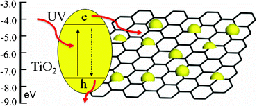 | ||
| Fig. 7 Schematic diagram of the energy levels of TiO2 and RGO. | ||
Photocatalytic reduction of Cr(VI) by TiO2, P25, TG-1, TG-2, TG-3 and TG-4 was performed under UV irradiation, as shown in Fig. 8. The normalized temporal concentration changes (C/C0) of Cr(VI) during the photocatalytic process are proportional to the normalized maximum absorbance (A/A0), which can be derived from the change in the Cr(VI) absorption profile at a given time interval. It is observed that TiO2–RGO composites with an appropriate proportion of RGO exhibit better photocatalytic performance than pure TiO2 and P25. The photocatalytic performance of the TiO2–RGO composite is dependent on the proportion of RGO in the composite. The removal rates of Cr(VI) for pure TiO2 and P25 are 83% and 70%. When RGO is introduced into TiO2, the removal rate is increased to 86% for TG-1 and reaches maximum value of 91% for TG-2. It is known that during photocatalysis, the light absorption and the charge transportation and separation are crucial factors.41 The enhancement of the photocatalytic performance should be ascribed to the increase of the light absorption intensity and range, and the reduction of electron-hole pair recombination in TiO2 in the presence of RGO in the composite, which have been confirmed from absorption and PL measurements. However, when the RGO content is further increased above its optimum value, the photocatalytic performance deteriorates. This is ascribed to the following reasons: (i) RGO may absorb some UV light and thus there exists a light harvesting competition between TiO2 and RGO with the increase of RGO content, which lead to the decrease of the photocatalytic performance;53 (ii) the excessive RGO can act as a kind of recombination center instead of providing an electron pathway and promote the recombination of electron-hole pairs in RGO.17,63
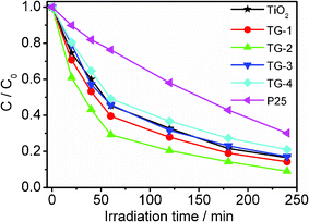 | ||
| Fig. 8 Photocatalytic reduction of Cr(VI) by TiO2, P25, TG-1, TG-2, TG-3 and TG-4 under UV irradiation. The concentrations of Cr(VI) and the photocatalyst are 10 mg l−1 and 1 g l−1, respectively. | ||
4. Conclusions
TiO2–RGO composites are successfully synthesized via microwave-assisted reduction of GO in the TiO2 suspension using a microwave system and their photocatalytic performances are investigated. The experimental results indicate that (i) TiO2–RGO composites exhibit a better photocatalytic performance than pure TiO2 and P25. (ii) The photocatalytic performance of TiO2–RGO is dependent on the proportion of RGO in the composite and the TiO2–RGO composite with 0.8 wt.% RGO achieves the highest Cr(VI) removal rate of 91%. (iii) The enhanced photocatalytic performance is ascribed to the increased light absorption intensity and range as well as the reduction of the photoelectron-hole pair recombination in TiO2 upon the introduction of RGO.Acknowledgements
Financial support from Special Project for Nanotechnology of Shanghai (No. 1052 nm02700) is gratefully acknowledged.References
- J. F. Shen, Y. Z. Hu, C. Li, C. Qin and M. X. Ye, Small, 2009, 5, 82–85 CrossRef CAS
.
- P. V. Kamat, J. Phys. Chem. Lett., 2010, 1, 587–588 CrossRef CAS
- J. F. Shen, Y. Z. Hu, M. Shi, X. Lu, C. Qin, C. Li and M. X. Ye, Chem. Mater., 2009, 21, 3514–3520 CrossRef CAS
- O. Akhavan, ACS Nano, 2010, 4, 4174–4180 CrossRef CAS
- Y. G. Li, H. L. Wang, L. M. Xie, Y. Y. Liang, G. S. Hong and H. J. Dai, J. Am. Chem. Soc., 2011, 133, 7296–7299 CrossRef CAS
- L. Y. Jiao, X. R. Wang, G. Diankov, H. L. Wang and H. J. Dai, Nat. Nanotechnol., 2010, 5, 321–325 CrossRef CAS
- X. R. Wang, X. L. Li, L. Zhang, Y. K. Yoon, P. K. Weber, H. L. Wang, J. Guo and H. J. Dai, Science, 2009, 324, 768–771 CrossRef CAS
- B. J. Li and H. Q. Cao, J. Mater. Chem., 2011, 21, 3346–3349 RSC
- Y. P. Zhang and C. X. Pan, J. Mater. Sci., 2010, 46, 2622–2626 CrossRef
- Z. Xiong, L. L. Zhang and X. S. Zhao, Chem.-A Eur. J., 2011, 17, 2428–2434 CrossRef CAS
- L. L. Zhang, J. Ma and X. S. Zhao, Chem. Commun., 2010, 46, 6099–6101 RSC
- P. V. Kamat, J. Phys. Chem. Lett., 2011, 2, 242–251 CrossRef CAS
- K. Zhang, L. L. Zhang, X. S. Zhao and J. Wu, Chem. Mater., 2010, 22, 1392–1401 CrossRef CAS
- L. L. Zhang, R. Zhou and X. S. Zhao, J. Mater. Chem., 2010, 20, 5983–5992 RSC
- K. Zhang, L. Mao, L. L. Zhang, H. S. O. Chan, X. S. Zhao and J. Wu, J. Mater. Chem., 2011, 21, 7302–7307 RSC
- H. L. Wang, L. F. Cui, Y. Yang, H. Sanchez Casalongue, J. T. Robinson, Y. Y. Liang, Y. Cui and H. J. Dai, J. Am. Chem. Soc., 2010, 132, 13978–13980 CrossRef CAS
- G. Zhu, T. Xu, T. A. Lv, L. K. Pan, Q. F. Zhao and Z. Sun, J. Electroanal. Chem., 2011, 650, 248–251 CrossRef CAS
- L. Kavan, J. H. Yum and M. Gratzel, ACS Nano, 2011, 5, 165–172 CrossRef CAS
- K. S. Kim, Y. Zhao, H. Jang, S. Y. Lee, J. M. Kim, K. S. Kim, J. H. Ahn, P. Kim, J. Y. Choi and B. H. Hong, Nature, 2009, 457, 706–710 CrossRef CAS
- Z. Y. Yin, S. Y. Sun, T. Salim, S. X. Wu, X. Huang, Q. Y. He, Y. M. Lam and H. Zhang, ACS Nano, 2010, 4, 5263–5268 CrossRef CAS
- W. T. Zheng, Y. M. Ho, H. W. Tian, M. Wen, J. L. Qi and Y. A. Li, J. Phys. Chem. C, 2009, 113, 9164–9168 CAS
- W. B. Zou, J. W. Zhu, Y. X. Sun and X. Wang, Mater. Chem. Phys., 2011, 125, 617–620 CrossRef CAS
- J. T. Zhang, Z. G. Xiong and X. S. Zhao, J. Mater. Chem., 2011, 21, 3634–3640 RSC
- Y. H. Ng, A. Iwase, A. Kudo and R. Amal, J. Phys. Chem. Lett., 2010, 1, 2607–2612 CrossRef CAS
- Y. H. Ng, I. V. Lightcap, K. Goodwin, M. Matsumura and P. V. Kamat, J. Phys. Chem. Lett., 2010, 1, 2222–2227 CrossRef CAS
- Y. Y. Liang, H. L. Wang, H. Sanchez Casalongue, Z. Chen and H. J. Dai, Nano Res., 2010, 3, 701–705 CrossRef CAS
- P. Wang, Y. M. Zhai, D. J. Wang and S. J. Dong, Nanoscale, 2011, 3, 1640–1645 RSC
- G. Williams, B. Seger and P. V. Kamat, ACS Nano, 2008, 2, 1487–1491 CrossRef CAS
- P. V. Kamat, J. Phys. Chem. Lett., 2010, 1, 520–527 CrossRef CAS
- O. Akhavan and E. Ghaderi, J. Phys. Chem. C, 2009, 113, 20214–20220 CAS
- O. Akhavan, M. Abdolahad, A. Esfandiar and M. Mohatashamifar, J. Phys. Chem. C, 2010, 114, 12955–12959 CAS
- N. J. Bell, Y. H. Ng, A. Du, H. Coster, S. C. Smith and R. Amal, J. Phys. Chem. C, 2011, 115, 6004–6009 CAS
- Y. H. Ng, A. Iwase, N. J. Bell, A. Kudo and R. Amal, Catal. Today, 2011, 164, 353–357 CrossRef CAS
- T. N. Lambert, C. A. Chavez, B. Hernandez-Sanchez, P. Lu, N. S. Bell, A. Ambrosini, T. Friedman, T. J. Boyle, D. R. Wheeler and D. L. Huber, J. Phys. Chem. C, 2009, 113, 19812–19823 CAS
- F. Zou, Y. Yu, N. Cao, L. Z. Wu and J. F. Zhi, Scr. Mater., 2011, 64, 621–624 CrossRef CAS
- X. Y. Zhang, H. P. Li, X. L. Cui and Y. H. Lin, J. Mater. Chem., 2010, 20, 2801–2806 RSC
- .J. J. Guo, S. M. Zhu, Z. X. Chen, Y. Li, Z. Y. Yu, Q. L. Liu, J. B. Li, C. L. Feng and D. Zhang, Ultrason. Sonochem., 2011, 18, 1082–1090 CrossRef
- W. Q. Fan, Q. H. Lai, Q. H. Zhang and Y. Wang, J. Phys. Chem. C, 2011, 115, 10694–10701 CAS
- J. F. Shen, B. Yan, M. Shi, H. W. Ma, N. Li and M. X. Ye, J. Mater. Chem., 2011, 21, 3415–3421 RSC
- J. F. Shen, M. Shi, B. Yan, H. W. Ma, N. Li and M. X. Ye, Nano Res. DOI:10.1007/s12274-12011-10136-12277
- H. Zhang, X. J. Lv, Y. M. Li, Y. Wang and J. H. Li, ACS Nano, 2010, 4, 380–386 CrossRef CAS
- Y. H. Zhang, Z. R. Tang, X. Z. Fu and Y. J. Xu, ACS Nano, 2010, 4, 7303–7314 CrossRef CAS
- K. F. Zhou, Y. H. Zhu, X. L. Yang, X. Jiang and C. Z. Li, New J. Chem., 2011, 35, 353–359 RSC
- Z. Li, Y. G. Yao, Z. Y. Lin, K. S. Moon, W. Lin and C. P. Wong, J. Mater. Chem., 2010, 20, 4781–4783 RSC
- W. Chen, L. Yan and P. R. Bangal, Carbon, 2010, 48, 1146–1152 CrossRef CAS
- P. Periyat, N. Leyland, D. E. McCormack, J. Colreavy, D. Corr and S. C. Pillai, J. Mater. Chem., 2010, 20, 3650–3655 RSC
- Z. Q. Chen, W. J. Zeng, W. K. Li, Z. H. Zhou and H. Y. Yu, Adv. Mater. Res., 2010, 177, 357–360 CrossRef
- A. V. Murugan, T. Muraliganth and A. Manthiram, Chem. Mater., 2009, 21, 5004–5006 CrossRef CAS
- C. T. Lee, F. S. Chen and C. H. Lu, J. Alloys Compd., 2010, 490, 407–411 CrossRef CAS
- F. Y. Jiang, C. M. Wang, Y. Fu and R. C. Liu, J. Alloys Compd., 2010, 503, L31–L33 CrossRef CAS
- G. Zhu, L. K. Pan, T. Xu and Z. Sun, ACS Appl. Mater. Interfaces, 2011, 3, 1472–1478 CAS
- X. J. Liu, L. K. Pan, T. Lv, T. Lu, G. Zhu, Z. Sun and C. Q. Sun, Catal. Sci. Technol., 2011 10.1039/C1031CY00109D
- T. G. Xu, L. W. Zhang, H. Y. Cheng and Y. F. Zhu, Appl. Catal., B, 2011, 101, 382–387 CrossRef CAS
- H. B. Li, T. Lu, L. K. Pan, Y. P. Zhang and Z. Sun, J. Mater. Chem., 2009, 19, 6773–6779 RSC
- Y. P. Zhang, H. B. Li, L. K. Pan, T. Lu and Z. Sun, J. Electroanal. Chem., 2009, 634, 68–71 CrossRef CAS
- T. Lu, L. K. Pan, H. B. Li, G. Zhu, T. Lv, X. J. Liu, Z. Sun, T. Chen and D. H. C. Chua, J. Alloys Compd., 2011, 509, 5488–5492 CrossRef CAS
- T. Lu, Y. P. Zhang, H. B. Li, L. K. Pan, Y. L. Li and Z. Sun, Electrochim. Acta, 2010, 55, 4170–4173 CrossRef CAS
- H. A. Becerril, J. Mao, Z. Liu, R. M. Stoltenberg, Z. Bao and Y. Chen, ACS Nano, 2008, 2, 463–470 CrossRef CAS
- L. H. Tang, Y. Wang, Y. M. Li, H. B. Feng, J. Lu and J. H. Li, Adv. Funct. Mater., 2009, 19, 2782–2789 CrossRef CAS
- Y. J. Wang, R. Shi, J. Lin and Y. F. Zhu, Appl. Catal., B, 2010, 100, 179–183 CrossRef CAS
- L. W. Zhang, H. Y. Cheng, R. L. Zong and Y. F. Zhu, J. Phys. Chem. C, 2009, 113, 2368–2374 Search PubMed
- G. Zhu, L. K. Pan, T. Xu, Q. F. Zhao and Z. Sun, J. Alloys Compd., 2011, 509, 7814–7818 CrossRef CAS
- N. L. Yang, J. Zhai, D. Wang, Y. S. Chen and L. Jiang, ACS Nano, 2010, 4, 887–894 CrossRef CAS
| This journal is © The Royal Society of Chemistry 2011 |