Synthesis and characterization of silicone polymer/functionalized mesostructured silica composites†
Satyajit
Gupta
ab,
Praveen C.
Ramamurthy
*ab and
Giridhar
Madras
b
aDepartment of Materials Engineering, Indian Institute of Science, Bangalore, India. E-mail: praveen@materials.iisc.ernet.in; Fax: +91-80-2360-0472; Tel: +91-80-2293-2627
bCenter for Nano science and engineering, Indian Institute of Science, Bangalore, India. E-mail: giridhar@chemeng.iisc.ernet.in; Fax: +91-80-2360-8121; Tel: +91-80-2293-2321
First published on 14th September 2011
Abstract
A thermally stable and flexible composite has been synthesized by following a consecutive ‘two–step’, solvent free route. Silicone polymer containing internal hydrides was used as a polymer matrix and mesoporous silica functionalized with allytrimethoxysiloxane was used as a filler material. In the second step, the composite preparation was carried out using the hydrosilylation reaction mediated by ‘Karastedt’ platinum catalyst. The results of the studies suggest that the composites are thermally stable, hydrophobic and flexible and can be potentially used for encapsulating flexible electronic devices.
Introduction
This work presents a development towards fabrication and characterization of flexible, thermally stable composite that can be used for the encapsulation of organic devices like organic field-effect-transistor (OFET) and photovoltaic-device (OPVDs) components for protection from the environment. It has been shown by various groups that in such devices the active device components, like the organic conducting polymer or small molecules as well as the electrode (Al or Ca) used, are vulnerable to degradation in the presence of moisture and oxygen.1–6 Hence the protection of such components is critical and essential in order to enhance the device lifetime.A silicone polymer was chosen as a matrix for this study because of its inherent inertness, thermal stability, moisture resistant properties and weatherability. It also adheres conformally at the surface, and shows flexibility over a broad temperature range. The flexible nature of the silicone material gives the ability to obtain flexible composites, that can be used in flexible electronic devices.7Oligosiloxane based material has been reported to be fabricated thermally as an encapsulant for organic light emitting diodes (OLEDs).8Oligosiloxane type (organic-inorganic hybrid) cured epoxy material has also been reported to be a good encapsulant for organic devices.9 Nanocomposite materials based on silicone polymers have also been developed,10,11 that can be potentially used for encapsulation of organic devices. In such composites, alumina provides a torturous pathway for the intrusion of deterrent molecules like moisture and oxygen. It has also been shown that inclusion of inorganic oxide nanoparticles (like Al2O3) reduces the gas permeability.12
Mesoporous silica was chosen as a filler material for the present study as it enhances the thermo-mechanical properties of the composites due to the confinement of the polymers in the mesopores at the interphase.13,14 It is reported that radical scavenging activity of silica component can enhance the thermal stability of the PMMA-mesoporous silica composite.14
The filler component, ‘allyl functionalized silica’ particles, can serve a dual purpose inside the composite. These impregnated functionalized particles inside the polymer matrix create a barrier in the diffusion pathway for the ‘deterrent’ molecules as well as adsorbing such molecules and thus can reduce the intrusion of permeant gases. Furthermore, the particles (having surface non-polar allyl groups) in the matrix can react with the polymer chain (Si–H) and anchor along the polymer molecules. Those covalent bindings are important for a composite as load transfer to the inorganic phase is possible through those bonds. Thus the combination of such components to fabricate a composite matrix will provide a suitable enclosure-material for the organic device. The use of such composites (prepared through a solvent free ‘two-step’ method) for encapsulation will be simple, easy to fabricate, less time consuming, high throughput and less energy expensive, as compared to the existent organic/inorganic multi-layered (multiple dyads) encapsulation.15Atomic layer deposition (ALD) and molecular layer deposition (MLD) have been used as the methods have excellent advantages, but it suffers from low throughput and limitation in the scalability of the fabrication process.16
In the present study, mesoporous silica was functionalized with ATMS (allyltrimethoxysilane), which provides a silica surface, decorated with allyl groups. The surface grafting was monitored by using various chemical as well as surface analysis and phenomenon-based techniques. The dangling surface allyl groups were further utilized for hydrosilylation reaction with the Si–H of the polymer through Pt-catalysed hydrosilylation reaction to obtain the functionalized composite material. Various studies of the composites like thermogravimetric analysis (TGA), dynamic mechanical analysis (DMA), contact angle measurement and scanning electron microscopy (SEM) were carried out to evaluate the properties of the composites.
Experimental section
Materials
Allyltrimethoxysilane (ATMS), platinum dimethyldivinylsilane [Karstedt catalyst: platinum (0)-1,3-divinyl-1,1,3,3-tetramethyldisiloxane complex, solution in xylene (∼2% Pt)]), silicone polymer (poly(dimethylsiloxane-co-methylhydrosiloxane) trimethylsilyl terminated, methylhydrosiloxane 3–4 mol %) of average Mn ∼ 13,000 and mesoporous silica (MSU-H, large pore 2D Hexagonal, d = 2.6 g cc−1) was obtained from Sigma-Aldrich Company Ltd. (St. Louis MO) USA. Analytical-reagent-grade toluene (from local suppliers, S D Fine Chem.) was distilled over pressed sodium and was preserved under inert atmosphere before use.Surface functionalization of mesoporous silica with allyltrimethoxysilane (ATMS)
In order to functionalize the surface, dried mesoporous silica particles (0.2 g) were dispersed by sonication in dry toluene followed by addition of ATMS (1 ml, 5.94 mmol) and refluxed17,18 for 20 h under inert (nitrogen) atmosphere (Scheme 1a). The powder was then separated by centrifugation, washed several times with toluene to remove the unreacted siloxane (ATMS) moieties and then dried under vacuum. | ||
| Scheme 1 (a) Functionalization of mesoporous silica with allyltrimethoxy silane (b) preparation of the composite matrix. The scale bar for the TEM image in (a) is 100 nm and the scale bar for the SEM image in (b) is 200 μm. | ||
Hydrosilylation reaction for attachment of the silicone polymer with the functionalized silica
Allyl functionalized silica particles of 0.6 and 1.5 wt % were dried at 130 °C for several hours under vacuum, mixed with the silicone polymer matrix and then dispersed using magnetic stirrer and further sonicated for 1 h at 50 °C to ensure homogeneous mixing and dispersion. The following nomenclature has been adopted in this work - IHS1 and IHS2 denote 0.6 wt % and 1.5 wt % of particles, respectively. 15 mg of Karstedt catalyst [platinum (0)-1,3-divinyl-1,1,3,3-tetramethyldisiloxane complex, solution in xylene (∼2% Pt)]) was added to the mixture and stirred (Scheme 1b). The reaction temperature was determined by DSC analysis and was found to occur at 145 °C. Hence, the reaction was carried out at about 135 °C in finely polished stainless steel moulds. The reaction was carried out under 30 mm Hg vacuum for 1 h to remove hydrogen gas which is produced consequently during the hydrosilylation reaction.Characterization
A Perkin-Elmer (Spectrum GX) spectrometer was used to obtain the FTIR (Fourier transform infrared) spectra of both pristine and functionalized silica particles, in order to evaluate the surface functionalization. The spectra were recorded using the potassium bromide (KBr) pellet method for both powder samples in the range 400 to 4000 cm−1 with a resolution of 4 cm−1. Solid state 29Si (one pulse experiment) for both pristine silica and functionalized silica were recorded in 300 MHz Bruker DSX with a relaxation delay of 12s. The surface area of the pristine as well as functionalized silica was measured by the Brunauer-Emmett-Teller (BET) nitrogen sorption method at 77 K with a Belsorp instrument, Japan. For the nitrogen adsorption/desorption experiments, both the samples were degassed at 130 °C for 6 h. The quantification of ATMS was carried out by elemental (C, H and N) analysis and thermogravimetric analysis (TGA). The TGA analysis was carried out using a high-resolution TGA 2950 apparatus (NETZSCH- STA 409PC) with a heating rate of 10 °C min−1 in an alumina crucible to evaluate the surface functionalization as well as the thermal stability of the composites. A Thermo Finnigan FLASH EA 1112 analyzer was used for elemental (C, H and N) analysis. In order to monitor the curing reaction and thermal history of the composites, differential scanning calorimetry (DSC) was carried out in Mettler Toledo (DSC 822e) instrument in argon atmosphere at a flow rate of 80 mL min−1 in a hermitic aluminium pan at varying heating rates.Rheometric study of the curing reaction was carried out in an AR-G2 rheometer (TA- instruments). The samples were analyzed in the parallel plate method at a frequency of 1 Hz and strain rate of 1% in the temperature range of 25 to 200 °C at a heating rate of 10 °C min−1. The morphologies of the cross-sectional surface of the cryogenically fractured surfaces of the composites were observed using scanning electron microscopy (SEM), which was carried out using ESEM Quanta instrument. Prior to the SEM analysis, samples were sputter-coated with thin film of gold using JEOL (JFC-1100E) ion sputtering device. The pristine silica powder sample was dispersed in ethanol and drop cast over the carbon tape, dried and was sputter coated with gold. JEOL 2000 FX–II TEM was used to observe the size and morphology of the silica at an accelerating voltage of 200 kV. The specimen was dispersed in ethanol by ultrasonication, and then drop cast on a Cu grid with a carbon-reinforced plastic film and then dried.
The specific gravity of the composites was measured using a density gradient column. The test was carried out as described in ASTM D1505. The density gradient column was prepared by using ethanol (d = 0.816) and carbon tetrachloride (d = 1.59). The standard apparatus consists of a glass column of 1 m long containing the solution of ethanol (EtOH) and carbon tetrachloride (CCl4), which has a linear density gradient from the top (lower density) to the bottom (higher density) of the column. The mixtures of EtOH/CCl4 v/v: 100/0, 90/10, 80/20, 70/30, 60/40, 50/50, 40/60, 30/70, 20/80, 10/90, 0/100 were prepared and carefully poured down the sides of the gradient tube to avoid mixing of the layers. Standard calibrated density markers in the form of glass beads (H & D Fitzgerald Ltd., St. Asaph, UK) along with the composites were dropped into the column slowly. The specific gravity of the composites was determined by comparing the position of the composites with that of the standards.19
For analysis of the mechanical properties, DMA (MetraVib DMA+100) was used in compression mode at a frequency of 1 Hz in a temperature range from 25 °C to 200 °C. Nanoindentation experiments were carried out using a Hysitron triboindenter with a Berkovich tip (a 3-sided pyramidal diamond tip) to determine the elastic modulus. As the mechanical properties determined from nano-indentation are sensitive to the tip geometry, the tip area function was calibrated using a standard quartz sample. Because the loads used in indenting polymer films are very small, the tip area function was calibrated in the low depth ranges for determination of the modulus. Using this area function, nanoindentation experiments were carried out on single-crystal aluminium to cross check the standard elastic modulus, E, and hardness, H, values recommended by the manufacturer (75.1 ± 5% GPa and 360 ± 10% MPa, respectively). The standard deviation was within 5% for both these values, validating the tip calibration process. Ten indentations were made in each sample, and the average value was taken as the value for the composite. All the experiments were performed in a load controlled mode (at room temperature) at a peak load of 20 μN nm with a loading and unloading rate of 2 μN s−1. The indentor was allowed a pause (hold) time of 10 s at maximum load (total time profile of 30 s). Elastic modulus was determined by the Oliver Pharr method.20 The thermo mechanical analysis was carried in A TA instruments (Model - TMA Q400) from ambient condition to 250 °C (Probe - Expansion, Force - 0.02 N) at a heating rate of 5 °C min−1 under nitrogen atmosphere with a flow rate of 50 mL min−1. The ‘static contact angle’ measurements of the composites were carried out (25 °C) in an OCA 30 commercial goniometer (Dataphysics, Germany) containing stepper motor for controlling the volume of the liquid (millipore water) supplied from a microsyringe.
Results and discussion
Synthesis
The present work delineates a method to fabricate a composite matrix by a two step method (Scheme 1). In step 1, silica surface was decorated with bifunctional ‘allyl trimethoxy silane’ by refluxing dried silica and free allyltrimethoxysilane in dry toluene. The –CH2–HC![[double bond, length as m-dash]](https://www.rsc.org/images/entities/char_e001.gif) CH2 (allyl) terminals at the surface makes the surface non-polar and it becomes compatible with the polymer matrix (Scheme 1A). The composite fabrication was carried out in step 2, where a hydrosilylation coupling methodology was applied, in which the allyl group reacts with Si–H in the presence of the Karstedt-Pt catalyst (Scheme 1B).
CH2 (allyl) terminals at the surface makes the surface non-polar and it becomes compatible with the polymer matrix (Scheme 1A). The composite fabrication was carried out in step 2, where a hydrosilylation coupling methodology was applied, in which the allyl group reacts with Si–H in the presence of the Karstedt-Pt catalyst (Scheme 1B).
Characterization of functionalization of silica: FTIR analysis, 29Si solid state NMR and Brunauer-Emmett-Teller (BET) nitrogen adsorption isotherm analysis
The FTIR spectra of pristine and modified silica are shown in Fig. 1(a) and (b). Some new peaks appear in the spectra after surface modification, which is due to ATMS grafting. In pristine silica, the peak at 3434 cm−1 is due to the surface OH stretching (Si–OH) and the peak at 1634 cm−1 is due to −OH bending vibration. After ATMS treatment (Step 1), the peaks observed at 2932 and 2854 cm−1 are due to asymmetric and symmetric stretching of –CH2, respectively. CC–H asymmetric stretching and symmetric stretching, peaks were observed at 3086 and 2980 cm−1 respectively.
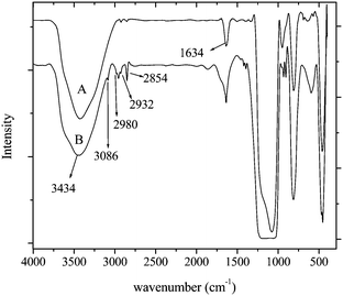 | ||
| Fig. 1 FTIR spectra of (a) pure (a) and (b) functionalized silica. | ||
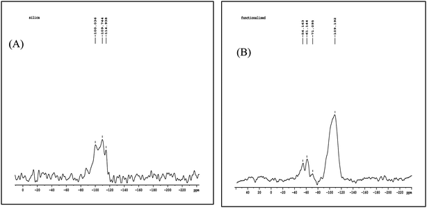
The 29Si NMR spectrum of the untreated silica shows (Fig. 2) three signals at −100.036 (Q2), −109.744 (Q3), and −114.938 (Q4) ppm, which can be assigned to geminal silanols, free silanols,18 and siloxane groups of neat silica, respectively. For the functionalized silica new peaks appearing at −54.163 (T1), −61.144 (T2) and −71.095 (T3) ppm is due to chemical grafting of the organic ligand in various modes of trifunctionalsilane-ATMS.18 The peaks observed in the range from −50 to −80 ppm indicate that the silica surface is chemically modified.21
The surface area of the pristine silica was calculated to be 679.6 m2 g−1 with an average pore size of 5.87 nm. After functionalization, the average pore size increased, while the pore volume and the surface area decreased due to the functionalization of the organic moiety. The decrease in C constant which is related to the enthalpy of adsorption,22 suggest the decrease in interaction between adsorbate nitrogen molecules and the particle surface after chemical anchoring with siloxane ligand (Table 1). The adsorption/desorption isotherm are of type IV and have a H2 type of loop23 (Fig. 3). This behavior is due to mesoporous nature of the particles. The morphology of the mesoporous silica is shown in the inset of Fig. 3 and the TEM images of used silica are provided in the inset of Scheme 1. After functionalization, the mesoporosity is retained as observed in the BET adsorption/desorption curve for the functionalized silica. H2-type hysteresis loop resembles the ink-bottle pores.24 The shape of hysteresis loop after functionalization is similar, suggesting that the pore shape may not be significantly changed viasilane functionalization process.25
| Parameters | Neat silica | Functionalized silica |
|---|---|---|
| Surface area (aBET)/m2 g−1 | 679.6 | 399 |
| Total pore volume (P/P0 = 0.99)/cm3 g−1 | 0.99 | 0.74 |
| Vm/cm3(STP) g−1 | 156.2 | 91.6 |
| C | 124.8 | 72.8 |
| Mean pore diameter/nm | 5.9 | 7.4 |
| Carbon (From CHN analysis) | 0.38 | 9.25 |
| Hydrogen (From CHN analysis) | 1.42 | 2.23 |
![Nitrogen
adsorption/desorption isotherms for the pure and functionalized silica [Inset: SEM image of pristine silica].](/image/article/2011/PY/c1py00316j/c1py00316j-f3.gif) | ||
| Fig. 3 Nitrogen adsorption/desorption isotherms for the pure and functionalized silica [Inset: SEM image of pristine silica]. | ||
Quantification of surface grafting: TGA and elemental (C, H and N) analysis
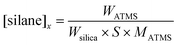
The surface functionalization of ATMS was also validated by thermal analysis. The comparative weight loss for pristine and functionalized silica from room temperature to 900 °C is shown in Fig. 4. Pristine silica shows some weight loss (∼6%) in the temperature range of 25 to 150 °C, which is due to the desorption of physically adsorbed water and some CO2. In case of functionalized silica, the weight loss between 50 to 150 °C is due to the loss of physically adsorbed moisture from the surface. The ATMS functionalized silica show less weight loss (∼3%) than pristine silica powder in this region. This is due to attachment of ATMS, which makes the silica surface hydrophobic. TGA analysis was further used to calculate the surface grafting density using ATMS by the following expression18,26where W150–730 is the weight loss from 150 to 730 °C, corresponding to the degradation of the silane and Wsilica is the weight loss of silica before functionalization. This indicates that the grafting density is about 1.54 ± 0.22 μmol m−2. The grafting density, calculated based on the weight loss between 60 to 730 °C, is 1.6 ± 0.2 μmol m−2.

![TGA analysis of pure and functionalized silica and the composites [Inset: DTA curves for the two composites].](/image/article/2011/PY/c1py00316j/c1py00316j-f4.gif) | ||
| Fig. 4 TGA analysis of pure and functionalized silica and the composites [Inset: DTA curves for the two composites]. | ||
After functionalization, an increase in the carbon was detected (Table 1) from elemental (C, H and N) analysis. The increase in the carbon content (ΔC) was used further to calculate the grafting density using Berendsen equation,27

The TGA and elemental (CHN) analysis was further used to calculate the grafting yield by the following expression,

In the above expression [silane]x is the initial concentration (μmol m2) of silane (non-hydrolyzed) and was calculated using the following equation,18
Characterization of composites
 | ||
| Fig. 5 (a) DSC thermogram of the curing reaction at various heating rates. (b) Variation of the peak curing temperature with the heating rate. | ||
The Kissinger method29 was used to determine the reaction activation energy from DSC studies. For a first order reaction, the conversion is related to time as,
| X(t) = 1 − exp(kt) |
During continuous heating, the reaction rate is a maximum at the peak curing temperature so that d/dt (dx/dt) = 0. Thus differentiating the above equation, and substituting β = dT/dt and equating it to zero yields,

Thus the peak curing temperature, Tc, at which the reaction rate is a maximum is related to the heating rate by the above equation, where Ea is the activation energy and A, a constant. Ea is determined from the slope of the plot (Fig. 5b) and is found be 15.9 kJ mol−1, which is comparable to that obtained for the curing of phenolic resins.30
The curing reaction was further evaluated by non-isothermal rheometry (heating rate of 10 °C min−1). In a curing reaction, the changes in the viscoelastic properties are reflected in the change of storage modulus (G′), loss modulus (G′′) and complex viscosity (η*). Initially, the storage modulus increases and crosses the G′′ curve after which the system solidifies. The complex viscosity (η*) also starts to increase at the proximity of gel point and finally becomes constant, indicating a cured, solid system. The various parameters extracted from rheometric study are shown in Fig. 6. The ‘gel point’ occurs when the resin system changes from a liquid to a rubbery state, as shown by ‘*’ in the curve which occurs at a temperature of ∼100 °C (cross-over of G′ and G′′31,32), showing a good agreement between DSC and rheological study. At higher temperatures, G′ becomes greater than G′′ indicating that the elastic region dominates over the viscous region.33 As the temperature increases, initially an increase in G′ was observed (but it does not cross G′′ curve) due to self-coupling34,35 (Si–Si) between the polymer chains.
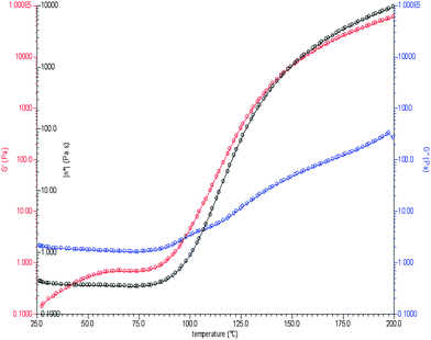 | ||
| Fig. 6 Rheometric study of curing. | ||
 | ||
| Fig. 7 SEM images of the fractured surface of the composites. | ||
Thermal properties of the composites: TGA, DSC and TMA
The TGA thermogram shows (Fig. 4) the degradation temperature is independent of nanoparticle loading. However, the final weight loss of IHS1 is higher than that of IHS2 because the polymer content of ISH1 is greater than IHS2. Only 2% weight loss is observed up to a temperature of 300 °C, indicating the thermal stability of the composites. Such thermal stability is important for a composite while it will protect the soft and sensitive device components from extreme environmental conditions. In order to verify any possible transition of the composites DSC was carried out in a range of −120 °C to 230 °C. The thermal history of the composites shows (see ESI, Fig. S3†) that there is no transition other than the one observed at −50 °C (Tg). This observation indicates that the composites can be used in a broad range of temperatures.Thermal expansion properties were evaluated using TMA. One of the important properties of an encapsulant is to have low shrinkage after curing and low coefficient of expansion, while hermetically sealing the device. Fig. 8 shows the expansion of the composites with respect to temperature, and the coefficient of expansion for the two composites were found to be 377.4 μm m−1 °C−1 for IHS2 and 381.7 μm m−1 °C−1 for IHS1. From the thermogram, it can be observed that there is no abrupt transition, which is in accordance with DSC analysis.
![Thermal mechanical analysis (TMA) of the two composites. [Inset: Contact angle measurement for the two composites (A) ISH1 (B) ISH2].](/image/article/2011/PY/c1py00316j/c1py00316j-f8.gif) | ||
| Fig. 8 Thermal mechanical analysis (TMA) of the two composites. [Inset: Contact angle measurement for the two composites (A) ISH1 (B) ISH2]. | ||
Mechanical characteristics: DMA and nanoindentation study
DMA of the samples were carried out in compression mode. Various parameters like E′ (real part), E′′ (imaginary part) i.e., the storage modulus and the loss modulus are extracted from the analysis and shown in Fig. 9. E′ (related to stiffness) represents the elastic properties of a material and E′′ represents the viscous properties. E* (complex modulus) is given by (E′ + iE′′). DMA result shows (Fig. 9) that E* ≈ E′ and E′ ≫ E′′ in a broad temperature range. This reflects that the material has more ability to store the applied force indicating the flexible nature of the composites.10 Further, no thermal transition (thermal event) occurs (also observed from the DSC and TMA of the composites as discussed earlier) in that region, showing that the material can be used in a wide range of temperature. It is also observed that the IHS2 shows higher storage modulus than IHS1 due to the higher crosslinking density in IHS2. | ||
| Fig. 9 DMA of the two composites at various temperatures. | ||
Nanoindentation is a versatile technique for the primary characterization of hard materials, like elasto-plastic properties of hard materials and for soft, elastomeric materials.37 It is observed that elastic recovery takes place after the removal of the load (Fig. 10) indicating the flexibility of the material, which is important for an encapsulant. The modulus values were calculated using the Oliver and Pharr method, which gives a relative modulus value, capable of differentiating between elastic moduli of soft materials.37 However, the modulus values were used in order to understand the effect of loading on modulus. The indentation modulus increases with increase in loadings (ISH1 - 0.002276 GPa and ISH2 - 0.004477 GPa respectively [see Fig. 10 Inset]). From Fig. 10, it is observed that, in case of IHS1, at lower load a deeper indentation depth was observed than in IHS2, which is due to less crosslink density. The result also indicate that the composites are soft and resilient, which are important properties for an encapsulant.8
![Load–penetration depth curves of two composites. [Inset: Modulus values of two different loadings (HS1 and HS2)].](/image/article/2011/PY/c1py00316j/c1py00316j-f10.gif) | ||
| Fig. 10 Load–penetration depth curves of two composites. [Inset: Modulus values of two different loadings (HS1 and HS2)]. | ||
Contact angle measurement
The contact angle for the lower loadings (ISH1) and higher loadings (ISH2) are 98.7 ± 1.5° and 102.5 ± 2°, respectively (inset of Fig. 8). This shows that both the composites are hydrophobic.Conclusions
The mesoporous silica surface was successfully modified with ATMS, which provides multiple binding sites with the silicone polymer matrix. This modified silica was used as a filler matrix for the composite material. Composites were fabricated by hydrosilylation by using the ‘Karastedt’ Pt-catalyst. The effects of two different loadings of functionalized silica particles on various thermo-mechanical properties of the composites were evaluated. The as synthesized composites show good thermal stability, mechanical flexibility and hydrophobicity. The composites, IHS1 and IHS2, have similar thermal stability. However, IHS2 exhibits better mechanical properties such as higher storage modulus and indentation modulus compared to IHS1. Further, the contact angle of IHS1 is lower than IHS2 indicating IHS2 is more hydrophobic. Further studies are required to optimize the allyl functionalized silica in the polymer matrix. Such composite matrices can be potentially used for enclosing flexible electronic devices.Acknowledgements
S.G acknowledges the Council of Scientific and Industrial Research (C.S.I.R), New Delhi for financial support. The authors gratefully acknowledge Dr Roymohapatra and Mr Harsabardhan of the Aerospace Engineering Department, Indian Institute of Science, Bangalore for DMA studies and technical support from the Tribology lab, Mechanical Engineering department, Indian Institute of Science, Bangalore. The authors gratefully acknowledge Prof. Upadrasta Ramamurty and K. Eswar Prasad for nanoindentation studies, Dr G. S Avadhani for TEM studies, Department of Materials Engineering and TA instruments, Bangalore for rheological measurements.Notes and references
- R. D. Scurlock, B. Wang, P. R. Ogilby, J. R. Sheats and R. L. Clough, J. Am. Chem. Soc., 1995, 117, 10194–10202 CrossRef CAS.
- D. G. J. Sutherland, J. A. Carlisle, P. Elliker, G. Fox, T. W. Hagler, I. Jimenez, H. W. Lee, K. Pakbaz, L. J. Terminello, S. C. Williams, F. J. Himpsel, D. K. Shuh, W. M. Tong, J. J. Lia, T. A. Callcott and D. L. Ederer, Appl. Phys. Lett., 1996, 68, 2046–2048 CrossRef CAS.
- S. Cros, M. Firon, S. Lenfant, P. Trouslard and L. Beck, Nucl. Instrum. Methods Phys. Res., Sect. B, 2006, 251, 257–260 CrossRef CAS.
- L. M. Do, E. M. Han, Y. Nidome, M. Fujihira, T. Kanno, S. Yoshida, A. Maeda and A. J. Ikushima, J. Appl. Phys., 1994, 76, 5118–5121 CrossRef CAS.
- R. B. Ye, M. BaBa, K. Suzuki, Y. Ohishi and K. Mori, Thin Solid Films, 2004, 464–465, 437–440 CrossRef CAS.
- B. H. Cumpston, I. D. Parker and K. F. Jensen, J. Appl. Phys., 1997, 81, 3716–3720 CrossRef CAS.
-
H. Biebuyck and E. Haskal, US Pat., 5
![[thin space (1/6-em)]](https://www.rsc.org/images/entities/char_2009.gif) 734225, 1998.
734225, 1998. - J. S. Kim, S. Yang and B. S. Bae, Chem. Mater., 2010, 22, 3549–3555 CrossRef CAS.
- K. Jung, J. Y. Bae, S. J. Park, S. Yoo and B. S. Bae, J. Mater. Chem., 2011, 21, 1977–1983 RSC.
- S. Gupta, P. C. Ramamurthy and G. Madras, Polym. Chem., 2011, 2, 221–228 RSC.
- S. Gupta, P. C. Ramamurthy and G. Madras, Ind. Eng. Chem. Res., 2011, 50, 6585–6593 CrossRef CAS.
- J. S. Lin, M. H. Chung, C. M. Chen, F. S. Juang and L. C. Liu, J. Phys. Org. Chem., 2011, 24, 193–202 CrossRef CAS.
- X. Ji, J. E. Hampsey, Q. Hu, J. He, Z. Yang and Y. Lu, Chem. Mater., 2003, 15, 3656–3662 CrossRef CAS.
- F. A. Zhang, D. K. Lee and T. J. Pinnavaia, Polym. Chem., 2010, 1, 107–113 RSC.
- P. E. Burrows, G. L. Graff, M. E. Gross, P. M. Martin, M. Hall, E. Mast, C. C. Bonham, W. D. Bennett, L. A. Michalski, M. S. Weaver, J. J. Brown, D. Fogarty and L. S. Sapochak, Proc. SPIE–Int. Soc. Opt. Eng., 2001, 4105, 75–83 CAS.
- J. S. Park, H. Chae, H. K. Chung and S. I. Lee, Semicond. Sci. Technol., 2011, 26, 034001 CrossRef.
- N. Tsubokawa, A. Kogure and Y. Sone, J. Polym. Sci., Part A: Polym. Chem., 1990, 28, 1923–1933 CrossRef CAS.
- F. Pardal, V. Lapinte and J. J. Robin, J. Polym. Sci., Part A: Polym. Chem., 2009, 47, 4617–4628 CrossRef CAS.
- P. C. Ramamurthy, W. R. Harrell, R. V. Gregory and A. M. Rao, J. Electrochem. Soc., 2007, 154, H495–H499 CrossRef CAS.
- W. C. Oliver and G. M. Pharr, J. Mater. Res., 1992, 7, 1564–1583 CrossRef CAS.
- F. Bauer, H. Ernst, U. Decker, M. Findeisen, H. J. Glasel, H. Langguth, E. Hartmann, R. Mehnert and C. Peuker, Macromol. Chem. Phys., 2000, 201, 2654–2659 CrossRef CAS.
- S. Brunaur, P. H. Emmett and E. J. Teller, J. Am. Chem. Soc., 1938, 60, 309–319 CrossRef.
- K. S. W. Sing, D. H. Everett, R. A. W. Haul, L. Moscou, R. A. Pierotti, J. Rouquerol and T. Siemieniewska, Pure Appl. Chem., 1985, 57, 603–619 CrossRef CAS.
- N. Leventis, S. Mulik, X. Wang, A. Dass, V. U. Patil, C. Sotiriou-Leventis, H. Lu, G. Churu and A. Capecelatro, J. Non-Cryst. Solids, 2008, 354, 632–644 CrossRef CAS.
- J. A. Bae, S. H. Hwang, K. C. Song, J. K. Jeon, Y. S. Ko and J. H. Yim, J. Nanosci. Nanotechnol., 2010, 10, 290–296 CrossRef CAS.
- C. Bartholome, E. Beyou, E. Bourgeat-Lami, P. Chaumont and N. Zydowicz, Macromolecules, 2003, 36, 7946–7952 CrossRef CAS.
- G. E. Berendsen and R. D. Galan, J. Liq. Chromatogr. Relat. Technol., 1978, 1, 561 CrossRef CAS.
- M. Abboud, M. Turner, E. Duguet and M. Fontanille, J. Mater. Chem., 1997, 7, 1527–1532 RSC.
- H. E. Kissinger, Anal. Chem., 1957, 29, 1702–1706 CrossRef CAS.
- Y. K. Lee, D. J. Kim, H. J. Kim, T. S. Hwang, M. Rafailovich and J. Sokolov, J. Appl. Polym. Sci., 2003, 89, 2589–2596 CrossRef CAS.
- H. H. Winter, Polym. Eng. Sci., 1987, 27, 1698–1702 CAS.
- R. Chavez, E. Ionescu, C. Balan, C. Fasel and R. Riedel, J. Appl. Polym. Sci., 2011, 119, 794–802 CrossRef CAS.
- S. Gupta, G. Madras, P. C. Ramamurthy, Thermochimica Acta, DOI:10.1016/j.tca.2011.06.017.
- K. A. Brown-Wesley, Organometallics, 1987, 6, 1590–1591 CrossRef.
- L. N. Lewis, J. Am. Chem. Soc., 1990, 112, 5998–6004 CrossRef CAS.
- T. H. Ho and C. S. Wang, Eur. Polym. J., 2001, 37, 267–274 CrossRef CAS.
- F. Carrillo, S. Gupta, M. Balooch, S. J. Marshall, G. W. Marshall, L. Pruitt and C. M. Puttlitz, J. Mater. Res., 2005, 20, 2820–2830 CrossRef CAS.
Footnote |
| † Electronic supplementary information (ESI) available. See DOI: 10.1039/c1py00316j |
| This journal is © The Royal Society of Chemistry 2011 |