Light driven asymmetric polymerization: an approach for tele-control reaction†
Hiromasa
Goto
* and
Kohsuke
Kawabata
Institute of Materials Science, Graduate School of Pure and Applied Sciences, University of Tsukuba, Tsukuba, Ibaraki 305-8573, Japan. E-mail: gotoh@ims.tsukuba.ac.jp; Fax: +81-298-53-4490; Tel: +81-298-53-5128
First published on 26th March 2011
Abstract
Chiroptical activity-tunable electro-polymerization is carried out in liquid crystal (LC) electrolyte solution under irradiation by UV or visible (Vis) light. The LC electrolyte prepared in this study undergoes photo-induced phase transition through trans–cisisomerization of an azobenzene-based chiral photo-isomerization dopant in the LC electrolyte solution. The trans–cisisomerization of the dopant induced by UV light changes the structural chirality of the cholesteric LC electrolyte solution, which allows chiroptical activity tuning under the polymerization conditions. The results demonstrate realization of light-commandable asymmetric polymerization through change in a chiral environment for the electro-polymerization reaction. Note that the chiral polymer thus synthesized shows redox (electrochemical doping/dedoping)-driven change in chiroptical activity. This method can be used to induce light-driven asymmetric chemical reactions.
Introduction
Electrochemical polymerization is a useful method for preparing electroactive π-conjugated polymers. These polymers thus prepared have been studied for applications in electrochromic devices,1 transparent electrodes, and sensors. The product of the reaction is in the form of a film on the electrode surface. Polymer films synthesized by the electrochemical method in isotropic solution exhibit neither linear dichroism nor circular dichroism (CD). Electrochemical polymerization (electro-polymerization) in liquid crystal (LC) has been developed,2 and the resultant polymers thus prepared display fingerprint texture,3 Schlieren texture,3 fan-shaped texture, or ellipsoidal texture4 under scanning electron microscopy (SEM) and polarizing optical microscopy (POM). This method previously developed by the author provides polymers with redox-driven chiroptically active function.5 Furthermore, the linearly polarized electrochromic effect was shown for the polymers with nematic, cholesteric, and smectic A (SmA) order prepared by electro-polymerization in LC under magnetic field.4Azobenzene is a well-known photosensitive chromophore that undergoes photo-induced cis–trans reversible isomerization. Command surface systems to control the molecular alignment have been studied by using azobenzene.6 The photochromic properties due to mechanical change7 in the molecular form can be applied for tuning of the reaction field.
Cholesteric LC is a twisted nematic phase of LC in which the directors are rotated progressively to form a helical structure. The helical aggregation of rod-like molecules in cholesteric LC results in periodicity, and the three-dimensional (3-D) molecular arrangement produces structural chirality.
Many living organisms possess cholesteric LC structures. The exoskeleton of insects with cholesteric order shows dazzling reflection of light. These are referred to as photonic insects. For example, the wings of golden beetles have multi-layer structure at the microscopic level.8 In particular, a jewel beetle cuticle consists of alternation of cholesteric layers and nematic layers of proteins.9 The polymer prepared in the present study shows rainbow-colored light reflection because the polymer forms a cholesteric LC-like structure.
The photo-induced phase transition can be applied for selective synthesis of optically active or inactive polymers or tuning of chiroptical activity by light. Photo-isomerizable molecules such as azobenzenes, spiropyranes, spiroxazine,10spiroperimidine11 and diarylethenes12 can be useful as photo-induced phase transition agents (photo-isomerization inducers) in LCs because the mechanical change in the molecular order of LC can lead to phase transition of the entire LC system. Small amounts of photo-isomerizable molecules in an LC matrix, therefore, can control phase transitions in the entire LC system. This function is comparable to the chiral dopant, which produces a cholesteric phase or chiral smectic phase (i.e., chiral smectic C, SmC*) from a nematic or achiral smectic phase (i.e., SmC) by addition of small amounts of optically active molecules. Here, small amounts of a compound with a particular property change a physical property of the entire system.
Addition of small amounts of molecules to an appropriate matrix is referred to as doping, and the agent as dopant. In this study, π-conjugated polymers are electrochemically synthesized in a photo-isomerizable LC electrolyte solution. The π-conjugated system in polymers is a precursor of conducting polymers because an addition of small amount of electron acceptor or donor to π-conjugated polymers produces electrically conducting systems through the generation of polarons as charge carriers.
The impurities (additives) of electron acceptor or donor are typical dopants in electronics. However, this study employs three types of doping effects in several research directions: (1) construction of cholesteric LC with a “chiral dopant” (LC chemistry research); (2) construction of photo-isomerization systems with a “photo-isomerization dopant” for a LC electrolyte solution (chemistry of photochromism); and (3) control of chiroptical activity for resultant redox-optically active polymers with electrochemical doping (oxidation) (“electro-dopant”, electronics), as shown in Scheme S1, ESI†. In this study, an azobenzene derivative with chirality is employed as a chiral photo-isomerization dopant. The compound has two functions—chiral dopant and photo-isomerization dopant. Also, chiroptical activity-tuning by light-driven electro-polymerization is carried out by using a photo-sensitive chiral matrix LC electrolyte solution containing the chiral azobenzene.
The polymerization in cholesteric LC and tuning of chiroptical activity with light may be comparable to biological processes in the exoskeleton of photonic insects, as a form of artificial biomimetic technology.
Experimental
Synthesis of photo-isomerization dopants
An azobenzene derivative having chiral carbon in its terminal alkyl group, (S)-(+)-4-butyl-[4-(1-methyl-heptyloxy)-azobenzene], abbreviated as AZO*, was synthesized for the preparation of the chiral photo-isomerization dopant (Scheme 1). 4-Butyl-4′-hydroxyazobenzene and (R)-(−)-octanol were coupled using diethyl azodicarboxylate (DEAD) and triphenylphosphine (TPP) in tetrahydrofuran (THF) solution, according to the Mitsunobu reaction. The absolute configuration at the chiral center in the terminal alkyl group was inverted to (S)-configuration via the Mitsunobu inversion mechanism of the SN2 reaction.13 The chemical structure of AZO* was confirmed by heteronuclear multiple quantum coherence (HMQC) 2-D 1H-13C correlation NMR spectroscopy (Fig. S1, ESI†). AZO* functions as a chiral dopant for the achiral nematic LC matrix for the formation of the cholesteric phase with structural chirality. The helical twisting power (β) of the AZO* in 4-n-hexyl-4′-cyanobiphenyl (6CB, matrix LC) is obtained as,| β = 1/pcr, |
 | ||
| Scheme 1 Synthesis of a chiral photo-isomerization dopant. (1) Diethyl azodicarboxylate, (DEAD), triphenylphosphine (TPP), tetrahydrofuran (THF). | ||
Synthesis of monomers
In this study, two types of monomers were employed, 2,3,2′,3′,2′′,3-hexahydro-[5,5′:7′,5′′]ter(thieno[3,4-b][1,4]dioxine), abbreviated as terEDOT, and 2,7-di(2-furyl)fluorine (furan–fluorene–furan, abbreviated as FFLF).Synthetic routes for the monomers were outlined in Scheme 2. The terEDOT was prepared by the previously reported method.3 FFLF was synthesized according to the Migita–Kosugi–Stille coupling reaction.152-(Tributylstannyl)furan and 2,7-dibromofluorene were coupled with the Pd(0)catalyst [Pd(PPh3)4] in toluene solution to yield FFLF with 88% yield.
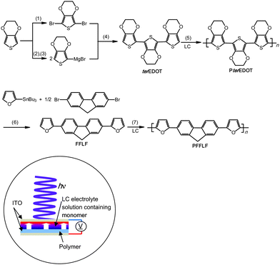 | ||
| Scheme 2 Synthesis of monomers and polymers. (1) N-Bromosuccinimide (NBS), CHCl3/glacial acetic acid.3 (2) n-BuLi, tetrahydrofuran (THF). (3) MgBr2·Et2O. (4) Ni(dppp)Cl2, THF. (5) Electro-polymerization under UV or Vis light in LC electrolyte solution. (6) Pd(PPh3)4, THF. (7) Electro-polymerization under UV or Vis light in LC electrolyte solution. LC = liquid crystal. Illustration shows polymerizationcell with incident light. | ||
Results and discussion
Photo-isomerization in chloroform solution
Fig. 1 shows changes in optical absorption spectra for AZO* in chloroform solution during irradiation of UV or Vis light. The absorptions at 350 nm (π–π* transition) due to the trans form weaken upon irradiation of UV light, accompanied by a strengthening of the absorption band at 440 nm (n–π* transition) due to the cis form. Subsequently, irradiation with Vis light caused an increase in the intensity of the absorption band at 350 nm, and a weakening of the band at 440 nm. These results suggest that reversible trans–cisisomerization and photochromic behavior of the azobenzene moiety occur upon UV and Vis light irradiation.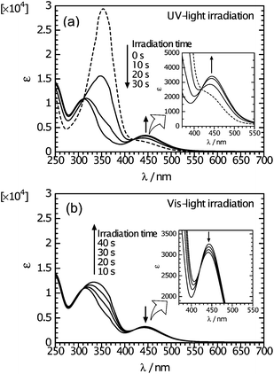 | ||
| Fig. 1 Changes in optical absorption spectra of AZO* in chloroform solution during irradiation of light. (a) UV irradiation (trans–cisisomerization). (b) Vis irradiation following UV irradiation (cis–transisomerization). Insets show spectra at higher magnifications. | ||
Photo-isomerization-driven change in optical texture
Photo-induced phase transition of the LC with AZO* was examined. The sample was sandwiched between thin glass slides (no spacer). The mixture containing AZO* (AZO* = 20 mg, 6CB = 0.3 g) showed the planar texture (Grandjean texture) of a cholesteric phase before irradiation of UV light. The optical texture rapidly changed from planar to fingerprint texture upon UV light irradiation (Fig. 2(a–c)). Here, the helical axis (structural chirality axis) of a cholesteric LC in the planar texture is normal to the substrate. However, the helical axis in the fingerprint texture is parallel to the substrate. In fact, the helical axis of the cholesteric liquid crystal turned from normal to parallel with respect to the substrate by UV light because light-induced molecular re-orientation occurred during the isomerization process of AZO* from trans to cis isomer in the LC matrix. Subsequently, the texture further turned into clear fingerprint structure, showing so-called cholesteric fingers (Fig. 2(d–f)). Further, the fingerprint released again and isotropic regions were extended (Fig. 2(g)). Finally, the liquid crystal was transformed into an isotropic phase because the cis isomer completely broke the LC order. Note that the Schlieren texture of a nematic phase was observed before a complete disappearance of the birefringence (Fig. 3(h)).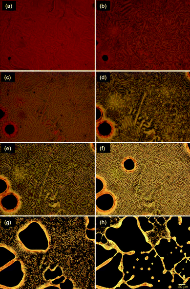 | ||
| Fig. 2 Changes in polarizing optical microscopic images of a cholesteric mixture containing AZO* under irradiation of UV light for (a) 0 s, (b) 4 s, (c) 10 s, (d) 14 s, (e) 18 s, (f) 20 s, (g) 24 s, (h) 26 s at 25 °C from cholesteric LC state. | ||
 | ||
| Fig. 3 POM images of Elyte-1 (Table 1) at an intermediate state of photo-induced transition from a cholesteric to an isotropic phase under UV irradiation. | ||
This behavior can be summarized in the following four steps: (1) planar texture; (2) change in helical axis direction; (3) transition from a cholesteric to a nematic phase; and (4) transition from a nematic to an isotropic phase. The change in the optical texture is derived from the isomerization process of trans–cisisomerization of AZO* in the LC matrix. Repeating isomerization afforded distinct fingerprint texture under Vis light (Fig. S2, ESI†). This result suggested that the cis/trans content in the entire system mechanically tunes the ordered state of the LC matrix. In other words, the particular quantity of the cis or trans isomer generated by light commands molecular orientation and mechanically induced phase transition for the entire LC system. The photo-induced phase transition by UV and Vis light irradiation repeated 5 times, respectively, showed no drop in performance, indicating good photostability. Good reversibility and reproducibility of azobenzenes have been proved by chemical motors.21
Preparation of cholesteric electrolyte solution
An LC electrolyte solution containing monomer was prepared to perform an electrochemical polymerization in the LC. The addition of small amounts of an optically active molecule as a chiral dopant to the nematic LC can induce the formation of cholesteric LC with a 3-D helical structure on a mesoscopic level.16,17 Firstly, AZO* was added to 6CB as a LC matrix. AZO* functions as both a chiral dopant and photo-isomerization dopant. Furthermore, tetrabutyl ammonium perchlorate (TBAP, (C4H9)4NClO4) was added to the electrolyte solutions as a supporting electrolyte.The constituents in the electrolyte solution for this electrochemical polymerization were as follows: (1) monomer (terEDOT or FFLF); (2) chiral photo-isomerization dopant (AZO*); (3) LCsolvent (6CB); and (4) supporting electrolyte (TBAP). The composition of the cholesteric LC electrolyte solutions (Elye-1, Elyte-2) and monomer structure are summarized in Table 1.
| Constituents of liquid crystal electrolyte solution containing monomera | |||
|---|---|---|---|
| Electrolyte solution | Monomer | Chiral photo-isomerization dopant | Matrix LC |
| a Supporting electrolyte = (C4H9)4NClO4 (tetrabutylammonium perchlorate, TBAP). | |||
| Elyte-1 |

|

|

|
| Elyte-2 |

|
||
The LC electrolyte solution was heated to completely dissolve TBAP, monomer, and the dopant in 6CB. These electrolyte solutions containing monomer exhibit thermotropic LC behavior and a typical fingerprint texture under POM at room temperature. The distance between two stripes corresponds to the half-pitch of the helical periodicity.
Electro-polymerization under irradiation of light
Electro-polymerization in the cholesteric LC electrolyte solution creates a chiroptically active polymer with a characteristic fingerprint structure, which is very similar to that of a cholesteric liquid crystal.3 In this study, electro-polymerization of the monomers in LC electrolyte solution containing the azobenzene derivative was carried out under irradiation of light. The photo-isomerization dopant isomerizes from trans to cis upon UV irradiation. The photo-isomerization of the dopant induces a phase transition of the LC electrolyte solution from a cholesteric to an isotropic phase. Therefore, light incident in the polymerizationcell can tune structural chirality of the LC electrolyte solution. Thus, electro-polymerization in the LC electrolyte solution with a photo-isomerization dopant allows optical tuning of the chiroptical activity of the polymer during the polymerization process.Electro-polymerization was carried out with the sandwitch-cellLCpolymerization method that the author previously developed.2 Prior to electrochemical polymerization, the LC electrolyte solution was heated in a vial under an argon atmosphere in order to completely dissolve the supporting electrolyte, the monomer, and the chiral photo-isomerization dopant in 6CB. The LC solution was injected by the capillary technique between two sandwiched indium-tin-oxide (ITO) coated glass electrodes with a Teflon sheet (thickness = 0.2 mm) used as a spacer (reaction cell). The reaction cell was initially heated (ca. 60 °C), and then gradually cooled to room temperature. Then, irradiation with Vis or UV light was carried out while applying a 4.0 V across the cell. The polymerization was either carried out in the dark after UV irradiation, or the polymerization was performed under Vis light (Scheme 2). After 30 min, an insoluble and infusible polymeric thin film was obtained, which coated the anode side of the ITO electrode. The film on the ITO was then washed with methanol, water, and acetone in that order, and dried to yield the polymer films.
Before polymerization of terEDOT, visual inspection of textural changes in the LC electrolyte solution containing the monomer (Elyte-1) was carried out in a thin glass cell. Fig. 3 shows an intermediate state of photo-isomerization for Elyte-1 observed with POM. The thickness of the cholesteric finger is extended (cholesteric finger corresponds to a helical half-pitch, and the length of half-pitch is extended) accompanied by the photo-isomerization upon UV light irradiation. The colorful texture completely disappeared upon further irradiation with UV light.
Fig. 4(a) shows a differential interference contrast optical microscopy (DIM) image of PterEDOT prepared in the cholesteric LC electrolyte solution containing AZO* under Vis light. The polymer surface shows a very similar structure to the exoskeleton microstructure of the littoral crab.18 The poly(terEDOT), abbreviated as PterEDOT exhibited a fingerprint texture and possessed the fibril structure. The fingerprint shape indicated that the structural chirality axis of the polymer thus obtained was parallel to the substrate surface due to its alignment in the electric field applied during the electro-polymerization4 conducted under the environmental conditions that resulted in the fingerprint texture.
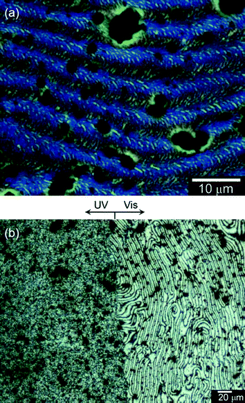 | ||
| Fig. 4 (a) Differential interference contrast optical microscopic (DIM) image of PterEDOT prepared in cholesteric LC electrolyte solution under the Vis light. (b) Polarizing optical microscopic (POM) image of PterEDOT prepared by electro-polymerization in the cholesteric liquid crystal solution containing a chiral photo-isomerization dopant (AZO*) showing a clear boundary. (Left) The polymer prepared after irradiation of UV light for 30 min. (Right) The polymer prepared under Vis light (this area was optically masked during the irradiation by UV light). | ||
Fig. 4(b) displays the POM image of the polymer, showing a clear boundary. The left side of Fig. 4(b) shows the UV irradiation segment, while the Vis irradiation segment is on the right side. This area was optically masked during the UV light irradiation. The left side shows a sanded texture, while the right displays a fingerprint texture. Furthermore, the Schlieren texture and a micro-organism-like texture are observed for the sample prepared under UV light in intermediate isomerization states of the LC electrolyte solution, as shown in Fig. S3 (ESI†).
Fig. 5 shows surface images of poly(2,7-di(2-furyl)fluorene) (PFFLF) prepared by the electro-polymerization in a cholesteric electrolyte solution containing AZO* (Elyte-2, Table 1) under irradiation of light. The image in Fig. 5(a) obtained with the DIM shows a characteristic labyrinthine convexo–concave structure of PFFLF prepared under Vis light irradiation. The SEM observation of the polymer supports this result, as shown in Fig. 5(b) and S4 (ESI†). These images suggest that transcription of the cholesteric LC order to PFFLF was carried out during the polymerization under Vis light. On the other hand, Fig. 5(c) (SEM image) shows predominantly a thread-like texture of nematic LC phase (and partially a fingerprint texture), which was produced by extension of the cholesteric helical pitch due to trans–cis photo-isomerization of AZO* upon UV light irradiation. Furthermore, completion of the photo-isomerization to cis-form of AZO* produces a polymer with no characteristic texture.
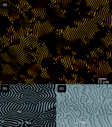 | ||
| Fig. 5 Surface images of poly(furan-fluorene-furan) (PFFLF) prepared by electrochemical polymerization in the cholesteric liquid crystal solution containing a chiral photo-isomerization dopant (AZO*). (a) Differential interference contrast optical microscopic (DIM) image of PFFLF. (b) Scanning electron microscopic (SEM) image of PFFLF. (c) SEM image of the polymer obtained after irradiation by UV light. | ||
Infrared absorption spectroscopy
Infrared (IR) absorption spectra of 6CB, AZO*, PterEDOT obtained by the KBr method are shown in Fig. S5, ESI†. The PterEDOT prepared under Vis light (PterEDOT (Vis)) and PterEDOT prepared after UV irradiation for 30 min (PterEDOT (UV30)) showed the same absorption bands, indicating that these polymers possessed the same chemical structure. The PterEDOTs displayed no characteristic absorption bands of 6CB (2227 cm−1, νCN, terminal CN group) and AZO* (1252 cm−1, νC–N![[double bond, length as m-dash]](https://www.rsc.org/images/entities/char_e001.gif) ). The IR measurements demonstrated that the present polymerization methods yielded pure polymers. These results also suggested that phase separation19 between the polymers and the matrix (dopants, 6CB) occurred during polymerization.
). The IR measurements demonstrated that the present polymerization methods yielded pure polymers. These results also suggested that phase separation19 between the polymers and the matrix (dopants, 6CB) occurred during polymerization.
Optical absorption
Optical absorption spectra of the polymer films on ITO in the monomer-free 0.1 M TBAP/acetonitrile solution during the application of voltage (vs.Ag/Ag+reference electrode) were examined. Fig. S6 (ESI†) shows these spectro-electrochemistry data for PterEDOT (UV30). An optical absorption band due to the π–π* transition of the main chain is observable at around 500 nm. The absorption intensity due to the π–π* transition of the main chain decreased with increasing voltage, while the absorption band at >800 nm strengthened, corresponding to generation of polarons (radical cation, doping band) on the main chain, which is a typical behavior for an electro-active polymer. In this case TBAP functions as an electro-dopant. The absorption intensities clearly changed between −0.5 V (de-doping, reduced) and +0.5 V (doping, oxidized). PterEDOT (Vis) showed the same tendency in the absorption spectra.Fig. S7 (ESI†) shows reversible changes in absorption for PterEDOT (Vis) on ITO glass with repeated scanning between −0.5 V and +0.5 V vs.Ag/Ag+ as a reference electrode in a monomer-free 0.1 M TBAP/acetonitrile solution. The absorption intensity was monitored at 508 nm (the π–π* transition of the main chain) and 852 nm (the polaron band). In the oxidation process at +0.5 V, the absorption intensity at 508 nm decreased, while that at 852 nm increased, whereas in the reduction process, the opposite trend was observed. These changes in absorption intensity were reproducible.
Optical rotatory dispersion
Optical rotatory power is one of the most interesting physical properties of asymmetric chemical materials. The plane of polarization of linearly polarized light is rotated in a chiral medium. This property of natural optical rotation of light is comparable to the Faraday effect in magnetic field and Kerr effect in electric field. Fig. 6(a) shows changes in optical rotatory dispersion (ORD) for the PterEDOT (Vis) under application of voltage between −0.5 V and +0.5 V vs.Ag/Ag+ as a reference electrode in a monomer-free 0.1 M TBAP/acetonitrile solution, demonstrating that the optical rotation of the polymer is controlled by the electrochemically applied voltage. Upon doping when the applied voltage was increased, an optical rotation in the visible region corresponding to absorption band of the π–π* transition of the main chain and optical rotation at long wavelengths were changed with an isosbestic point at around 720 nm. This result indicates that the polymer is electro-chiroptically active, i.e.redox-chiroptically active, and that the optical rotation is controlled by the electrochemical process.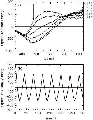 | ||
| Fig. 6 (a) Optical rotatory dispersion (ORD) spectra of PterEDOT prepared in cholestreric LC under Vis light (PterEDOT (Vis)) at various potentials. (b) Repeating change in the optical rotation at 584 nm with electrochemical doping–dedoping cycle in monomer-free 0.1 M TBAP/acetonitrile solution (50 mV s−1). | ||
The repeating change in the sign of the ORD in the redox process via change of the electronic state of the polymer indicated that the polymer forms a chiroptical structure, and that the chiroptical activity of the polymer can be changed by the external potential (Fig. 6(b)). The electrochemical potential change in the polymer produces a precise electronic doping level, with resulting changes in its electronic state. Thus, it is possible to control the optical rotation of the polymer by applying the voltage electrochemically. This phenomenon can be referred to as a redox (doping–dedoping)-driven control of chiroptical activity.5 The ORD results demonstrated that the LC electrolyte solution possessing structural chirality provides a chiral environment for the present polymerization.
Circular dichroism (CD)
Fig. 7 shows CD spectra of PterEDOTs at applied voltages from −0.5 V to +0.5 V. The polymer displayed a bisignate split-type CD shape at low voltage (reduced state, dedoping). The CD isosbestic point is found at the absorption maximum due to π–π* transition of the main chain. This suggested that the polymer shows an exciton coupling pattern. The bisignate band in the reduced state suggests the presence of an intermolecular process upon aggregate formation. The exciton coupling requires the presence of an unconjugated chromophore in the chiral arrangement, which can occur through interchain interaction between individual main chains in the aggregate state. In this case, the aggregate-induced band can be a charge transfer-type π-stacking of the polymer backbone. CD in the oxidized state suggests partly released chiral aggregation due to intercalation of perchlorate ion between the main chains by the redox process. This result indicated that the polymer in the oxidized state also forms a chiral structure.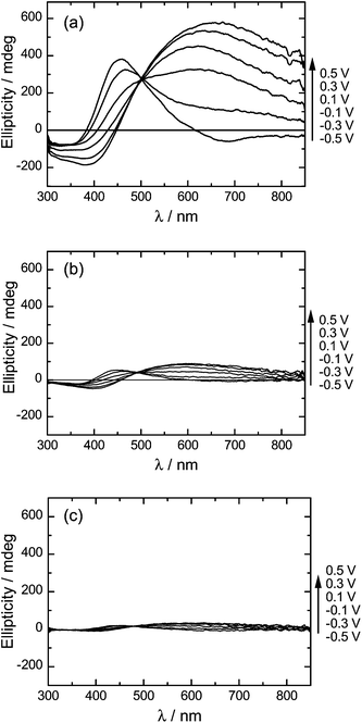 | ||
| Fig. 7 CD spectra of PterEDOTs during voltage application. (a) PterEDOT prepared in cholesteric LC under Vis light (PterEDOT (Vis)). (b) PterEDOT prepared in cholesteric LC after UV light irradiation for 30 min (PterEDOT (UV30)). (c) PterEDOT prepared in cholesteric LC after UV light irradiation for 60 min (PterEDOT (UV60)). | ||
The CD signals observed for the polymer cannot be due to AZO* because the absorption band appears in the short-wavelength region (<300 nm). These spectra confirm electro-chiroptically active behavior of the polymers. PterEDOT (Vis) consistently displayed intensity changes in CD spectra during the application of the voltage.
On the other hand, the polymers prepared after UV irradiation for 30 min (PterEDOT (UV30)) showed weak signals and small changes in the CD intensity as compared to those of the polymer prepared under Vis light. In particular, PterEDOT (UV60) made under UV irradiation for 60 min displayed relatively weak signals, indicating that the chiroptical activity was still present. This result demonstrates that the cis isomer of the photo-isomerization dopant generated under UV light disturbed the aggregation of structural chirality of the cholesteric LC. Polymerization in a depressed structural chiral field resulted in a decrease of optical activity for the resultant polymer. In other words, the external light tunes chiroptical activity during polymerization through tuning of structural chirality of the LC electrolyte solution. Fig. 8 shows repeating changes in the ellipticity of PterEDOT (Vis) and PterEDOT (UV30) during repeated voltage scanning from −0.5 V to +0.5 V vs.Ag/Ag+. In the oxidation process at +0.5 V, the CD band corresponding to the π–π* transition of the main chain in the visible region (PterEDOT (Vis): 457 nm, PterEDOT (UV30): 444 nm) decreased in intensity (Fig. 8(a and b)), while that at long wavelengths, corresponding to the doping band (PterEDOT (Vis): 658 nm, PterEDOT (UV30): 600 nm), intensified whereas the opposite trend was observed in the reduction process (Fig. 8(c and d)). These observed changes in the CD intensity were reproducible. The photo-isomerization during polymerization tunes the chiroptical activity of resultant polymers. The polymer prepared in the electrolyte solution in a completely isotropic state (in the isotropic temperature range) showed no chiroptical activity. Note that the optical properties of the polymer films exhibited no changes for 1 month in the air, indicating good environmental stability.
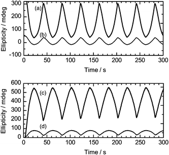 | ||
| Fig. 8 Repeating changes in the ellipticity of PterEDOT (Vis) and PterEDOT (UV30) during repeated voltage scanning from −0.5 V to +0.5 V vs.Ag/Ag+. (a) Changes in ellipticity of PterEDOT (Vis) (polymer prepared under Vis light irradiation) at 457 nm (absorption of π–π* transition of the main chain). (b) Changes in ellipticity of PterEDOT (PterEDOT (UV30)) at 444 nm (absorption of π–π* transition of the main chain). (c) Changes in ellipticity of PterEDOT (Vis) at 658 nm (the doping band, the polaron band). (d) Changes in ellipticity of PterEDOT (UV30) at 600 nm (the doping band, the polaron band). | ||
Diffraction
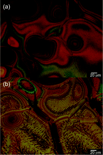
PFFLF showed a clear periodic convexo–concave structure. Laser transmission through the polymer film prepared from Elyte-2 under Vis light (PFELF (Vis)) produced a circular Fourier-transformed interference image with clear separation of red and green laser light (Fig. 9(a)) due to the random grating formed by the single-pitch helicity derived from stripes of the polymer. The red (λ = 670 nm) and green (λ = 532 nm) are projected to the outer and inner parts of the circular diffraction pattern, respectively. Upon irradiation with blue laser light at 473 nm, the polymer displayed diffraction for m = 1, 2, as shown in Fig. 9(b). The convexo–concave structure of the PFFLF (Vis) produced iridescent reflection and diffraction of light. Although the natural color of the PFFLF is dark brown in the half-doped state, the polymer film exhibited a rainbow-like reflection upon irradiation at certain angles with incident white light (Fig. 9(c)). This structural color originated from the helicity-based periodic convexo–concave structure of the polymer surface, similar to photonic insects showing structural color. On the other hand, the polymers prepared after irradiation of UV light (PFFLF (UV)) showed neither the diffraction nor the rainbow color reflection because the polymers possessed no periodic surface structure. This result suggested that the polymerization method employed in this study allowed UV/Vis light-driven separation synthesis of polymers for use in optical diffraction applications.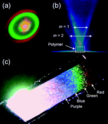 | ||
| Fig. 9 (a) Diffraction pattern under irradiation with combined red and green laser light for PFFLF (Vis). (b) Blue diffraction of PFFLF (Vis) at normal incidence. (c) Polymer film on ITO under white light showing iridescence with purple, blue, green, and red reflections. | ||
Plausible mechanism
Scheme 3 illustrates photo-isomerization of AZO* upon light irradiation, changes in the optical texture of the LC electrolyte solution (Scheme 3(a and b)), and SEM image of the resultant LC-free PterEDOTs film surface (Scheme 3(c and d)). Trans isomer of the azobenzene derivative shows good affinity for the LC medium, but the cis isomer mechanically deformed the chiral LC structure. The polymerization in the cholesteric phase of the LC medium containing the trans isomer of AZO* allowed production of a polymer having structural chirality and characteristic fingerprint texture with fibril structure viatranscription from structural chirality of the cholesteric LC medium. However, polymerization in the isotropic phase of the LC medium produced by the cis isomer of the photo-isomerization dopant yielded no chiral LC-like texture. It can be concluded that the external incident light can induce tuning of chiroptical activity of the resultant polymer through tuning of the photo-induced phase transition of the LC electrolyte solution in the polymerization reaction.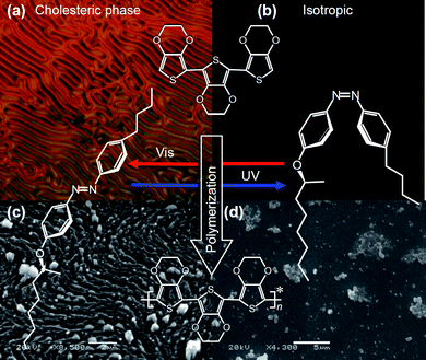 | ||
| Scheme 3 Light-driven asymmetric polymerization with a chiral photo-isomerization dopant. (a) POM image of cholesteric electrolyte solution containing AZO* (Elyte-1, Table 1) under Vis light. (b) Isotropic state produced by incident UV light. (c) SEM image of the polymer prepared in Elyte-1 under Vis light. (d) SEM image of non-ordered structure produced by UV light irradiation. | ||
Conclusions
The azobenzene derivative, AZO*, plays roles as both chiral dopant and photo-isomerization dopant. Photo-induced phase transition of AZO* in the LC electrolyte solution allows chiroptical activity tuning during polymerization. This study suggests a viable approach for tele-controllable asymmetric chemical reaction.Experimental
Synthesis
Elyte-2. FFLF (10 mg), 6CB (0.5 g), TBAP (2 mg), AZO* (50 mg).
Materials
2-(Tributylstannyl)furan (TCI, Tokyo Chemical Industry) and 2,7-dibromofluorene (TCI) were used as received. High-purity chloroform (Wako) was used without purification for optical measurements of the polymers. Toluene, THF (Wako Pure Chemical Industries), and EDOT (Aldrich) were purified with distillation prior to use. TBAP and cholesteryl nonanoate were obtained from Tokyo Kasei (TCI) Japan. 6CB was purchased from Merck. The ITO glass (Furuuchi Chemical Corporation) consists of a ca. 12 nm thick ITO layer on glass (9 Ω cm2).Techniques
All synthetic experiments (synthesis of monomers) were performed under an argon atmosphere using Schlenk/vacuum line techniques. 1H NMR spectra were measured in CDCl3 using a Bruker AV-600 FT-NMR spectrometer or JASCO 270 MHz EX-270spectrometer. Chemical shifts were recorded in parts per million downfield from tetramethylsilane (TMS) as an internal standard. Absorption spectra were obtained using a UV-Visspectrophotometer (Hitachi U-2000). Circular dichroism and optical rotation measurements were performed using a Jasco J-720spectrometer with an ORDE-307W ORD unit. Electrochemical measurements of polymers were conducted using an electrochemical analyser (μAutolab III, Autolab, The Netherlands), and optical textures were observed using a high-resolution polarizing microscope (Nikon ECLIPS LV 100) with a Nikon LU Plan Fluor and Nikon CFIUW lenses without oil immersion. Helical twisting power β was obtained with Grandjean–Cano wedge cell (EHC). UV light was generated with a UV lamp with an optical filter of 365 nm or a power-light emitting diode (LED, Nichia Chem. Co. NCSU033A). SEM images were obtained with JEOL JSM-521.Acknowledgements
The author is grateful to the Engineering Workshop of the University of Tsukuba for glasswork. NMR measurements were carried out by the Chemical Analysis Division of the Research Facility Center for Science and Technology, University of Tsukuba. This research was supported by Japan Society for the Promotion of Science (JSPS), Grant-in-Aid for Scientific Research, 22550161.References
- P. Beaujuge, S. Ellinger and J. R. Reynolds, Nat. Mater., 2008, 7, 795–799 CrossRef CAS.
- (a) H. Yoneyama, K. Kawabata, A. Tsujimoto and H. Goto, Electrochem. Commun., 2008, 10, 965–969 CrossRef CAS; (b) H. Goto, Res. Lab. Note, University of Tsukuba, 2000, vol. 24, p. 2401 Search PubMed.
- H. Goto, J. Mater. Chem., 2009, 19, 4914–4921 RSC.
- H. Goto and S. Nimori, J. Mater. Chem., 2010, 20, 1891–1898 RSC.
- (a) H. Goto, Phys. Rev. Lett., 2007, 98, 253901 CrossRef; (b) H. Goto, Res. Lab. Note, University of Tsukuba, 2004, vol. 30, p. 3100 Search PubMed.
- K. Ichimura, M. Kidowaki, H. Akiyama, K. Kudo, V. Strehmel and B. Strehmel, Macromol. Rapid Commun., 1996, 17, 545–551 CrossRef CAS.
- K. Uchida, N. Izumi, S. Sukata, Y. Kojima, S. Nakamura and M. Irie, Angew. Chem., Int. Ed., 2006, 45, 6470–6473 CrossRef CAS.
- A. E. Seago, P. Brady, J.-P. Vigneron and T. D. Schultz, J. R. Soc., Interface, 2009, 6, S165–S184.
- A. C. Neville, Biology of Fibrous Composites, Cambridge University Press, 1993 Search PubMed.
- S.-J. Lee, Y.-A. Son, H.-J. Suh, D.-N. Lee and S.-H. Kim, Dyes Pigm., 2006, 69, 18–21 CrossRef CAS.
- Y. Norikane, R. Davis, Y. Nishimura, T. Arai and N. Tamaoki, J. Photochem. Photobiol., A, 2009, 205, 116–121 CrossRef CAS.
- (a) K. Uchida, N. Nishikawa, N. Izumi, S. Yamazoe, H. Mayama, Y. Kojima, S. Yokojima, S. Nakamura, K. Tsujii and M. Irie, Angew. Chem., Int. Ed., 2010, 49, 5942–5944 CAS; (b) M. Ihie and M. Mohri, J. Org. Chem., 1988, 53, 803–808 CrossRef CAS.
- O. Mitsunobu and M. Yanada, Bull. Chem. Soc. Jpn., 1967, 40, 2380–2382 CAS.
- R. Cano, Bull. Soc. Fr. Mineral. Cristrallogr., 1968, 91, 20 Search PubMed.
- (a) M. Kosugi, K. Sasazawa, Y. Shimizu and T. Migita, Chem. Lett., 1977, 301–302 CAS; (b) D. Milstein and J. K. Stille, J. Am. Chem. Soc., 1978, 100, 3636–3638 CrossRef.
- G. Solladié and G. Zimmermann, Angew. Chem., Int. Ed. Engl., 1984, 23, 348–362 CrossRef.
- N. P. M. Huck, W. F. Jaeger, B. Lange and B. L. Fringe, Science, 1996, 273, 1686–1688 CrossRef CAS.
- Y. Bouligand, Tissue Cell, 1972, 4, 189–190 CrossRef CAS , 192–217.
- H. Kihara, T. Miura, R. Kishi and A. Kaito, Polymer, 2004, 45, 6357–6363 CrossRef CAS.
- K. Kawabata and H. Goto, Chem. Lett., 2009, 706–707 CrossRef CAS.
- M. Yamada, M. Kondo, J. Mamiya, Y. Yu, M. Kinoshita, C. J. Barrett and T. Ikeda, Angew. Chem., Int. Ed., 2008, 47, 4986–4988 CrossRef CAS.
Footnote |
| † Electronic supplementary information (ESI) available: POM images, UV spectra, DIM images, IR spectra and SEM image. See DOI: 10.1039/c0py00396d |
| This journal is © The Royal Society of Chemistry 2011 |
