Gyroid nanoporous scaffold for conductive polymers†
Fengxiao
Guo
ab,
Lars
Schulte
ab,
Weimin
Zhang
c,
Martin E.
Vigild
a,
Sokol
Ndoni
*b and
Jun
Chen
*c
aDanish Polymer Centre, Department of Chemical and Biochemical Engineering, Technical University of Denmark, DK-2800 Kgs, Lyngby, Denmark
bDepartment of Micro- and Nanotechnology, Technical University of Denmark, DK-4000, Roskilde, Denmark. E-mail: sond@nanotech.dtu.dk; Tel: +45 46774784
cIntelligent Polymer Research Institute, University of Wollongong, Wollongong, NSW 2522, Australia. E-mail: junc@uow.edu.au; Tel: +61 (2)42213781
First published on 30th November 2010
Abstract
Conductive nanoporous polymers with interconnected large surface area have been prepared by depositing polypyrrole onto nanocavity walls of nanoporous 1,2-polybutadiene films with gyroid morphology. Vapor phase polymerization of pyrrole was used to generate ultrathin films and prevent pore blocking. The resulting nanoporous polymers exhibited a promising electroactivity.
Polymeric materials with highly ordered nanopores have attracted considerable interest due to their unique nanometre-scaled structures. Self-assembly of diblock copolymers spontaneously yields ordered nanostructures, including spheres, cylinders, gyroid and lamellae. Selective removal of one block can generate nanoporous polymers. Such nanoporous polymers can be used as a scaffold for growing nanostructured materials with controlled morphologies. Using nanoporous polymers as templates to deposit conducting polymers may provide a means to shrink the dimensions of electrochemical and electronic devices.1–3
Polypyrrole (PPy) is one of the most common conducting polymers due to its simplicity of preparation, high conductivity and stability. A number of methods have been developed to produce PPy nanowires in both nanoporous organic and inorganic materials.3–6 In addition to PPy nanowires, PPy ultrathin film incorporated onto nanopores' wall surface of nanoporous polymers can also introduce conductivity to the previously insulating framework, meanwhile preserving the original porous structure. In this communication we present the fabrication of conductive monolithic nanoporous polymers by coating with PPy the nanopores' walls of gyroid nanoporous 1,2-polybutadiene (PB).
The procedure of preparation of conductive nanoporous polymers from original block copolymers is outlined in Scheme 1. The gyroid nanoporous PB monoliths (2 cm × 1 cm × 0.03 cm) were prepared from PB-b-PDMS by cross-linking the PB block with dicumyl peroxide followed by removal of the PDMS block with tetrabutylammonium fluoride according to ref. 7. The obtained monoliths are transparent, colorless and have pore diameter of 14 ± 1 nm, surface area of 270 ± 40 m2 g−1 and porosity of 40%.
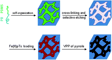 | ||
| Scheme 1 Schematic illustration of the preparation of conductive ordered nanoporous polymers. | ||
PPy thin film was deposited on the nanopores by vapor phase polymerization (VPP) of pyrrole with ferric p-toluenesulfonate (Fe(III)pTs) as an oxidant. Winther-Jensen et al. have reported that by using Fe(III)pTs oxidant VPP of pyrrole can leave very smooth and coherent coatings on a flat surface.8 Gyroid morphology is known for its bicontinuous network,9 so it is easy accessible to gases and liquids, and probably less apt to show pore blockage. The combination of VPP of pyrrole with Fe(III)pTs oxidant and gyroid morphology of nanoporous PB is to make continuous conductive PPy coatings throughout the nanopores. From Table 1, we can see that the mass of PPy in nanoporous PB increases with oxidant concentration.
To obtain evidence of PPy impregnation into nanoporous PB, Fourier transform infrared (FT-IR) spectra of the film before and after modification were measured. As shown in Fig. 1 additional characteristic peaks associated with PPy appear in the spectrum of the modified film compared to the spectrum of the PB precursor: PB-PPy-III at 1550 cm−1 (ring stretching), 1180 and 1040 cm−1 (in-plane deformation of C–H bond). Furthermore, intensities of the two characteristic PPy peaks increase with increasing concentration of Fe(III)pTs (see Fig. S1†). This is an indication that more PPy forms in the presence of more Fe(III)pTs. Ultraviolet-visible (UV-Vis) spectroscopy was further used to confirm the presence of PPy in nanoporous PB. Fig. 2 shows that the PB precursor does not absorb any radiation in the range from 350 to 900 nm. After modification the typical π–π* absorption of conjugated PPy takes place at 430 nm. In addition, a broad band at 850 nm can be assigned to the extended conjugation in the backbone of PPy. As expected, the film containing more PPy absorbs more in these two broad wavelength ranges (see Fig. S2†).
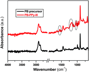 | ||
| Fig. 1 FT-IR spectra of PB precursor and PB-PPy-III. | ||
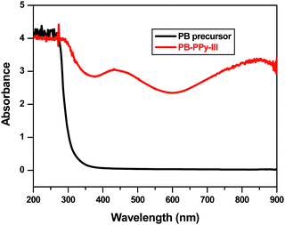 | ||
| Fig. 2 UV-Vis spectra of PB precursor and PB-PPy-III. | ||
To investigate the thickness of PPy coating on the pore walls, PPy thin films were prepared on glass slides at same conditions as for nanoporous PB. The coating thickness was measured by a DekTak profilometer. Fig. 3 shows the relationship between the coating thickness and absorbance of the coating at 430 nm. Based on this relation, extrapolated up to an absorbance value of 4, the average coating thickness on pore walls of nanoporous PB can be calculated. Values for the four samples are close to the results obtained from mass uptake method,10 and are smaller than 1 Å, which means that the pore walls are not covered completely, and the distribution of the coating is not homogeneous.
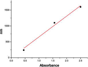 | ||
| Fig. 3 Relationship between PPy coating thickness and absorbance of the coating at 430 nm. | ||
PPy inside the gyroid network of nanoporous PB was investigated at room temperature by doing Raman spectroscopy on the cross section of PB-PPy-III at 632.8 nm diode laser excitation and a 300 lines per mm grating. The Raman spectrum in Fig. 4 is typical for PPy, similar to that of pure PPy polymerised under identical conditions. This not only confirms that the resulting composite material contains PPy but also indicates that PPy coating has been incorporated into the whole thickness of the nanoporous PB.
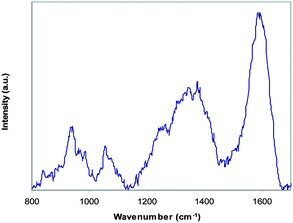 | ||
| Fig. 4 Raman spectrum of PB-PPy-III with a 632.8 nm laser excitation and a 300 lines per mm grating. | ||
Small angle X-ray scattering (SAXS) was used to investigate the morphology of nanoporous PB after modification. Fig. 5 shows 1D scattering curves for the nanoporous PB precursor and PB-PPy-III. The two profiles are virtually identical, both in intensity and in scattering features. This is proving that both structure and porosity have been preserved under the deposition process. The ratios of the scattering vector length q for the marked peaks are characteristic for the gyroid morphology. Transmission electron microscopy (TEM) was employed to directly visualize the nanoporous structure. Fig. 6 shows images of the PB precursor and of the sample PB-PPy-III. Both images were observed nearly along the [111] direction. The centre to centre distances in this projection, also known as the “wagon wheel” projection (36 ± 2 nm for PB precursor and 36 ± 1 nm for PB-PPy-III) as calculated by using the trigonometric relationships were in good agreement with those obtained from SAXS analysis (twice the spacing of the {211} planes, that is 37 nm for both samples). There is no observation of blocked pores or grainy structure of PPy particles in the pores over the whole area of 1.5 µm × 1.5 µm in the TEM image of PB-PPy-III. This reconfirms, as already proved by SAXS, that the gyroid morphology and open pores were fully preserved after incorporation of PPy and that consequently PPy was deposited onto the nanopore wall surface. The higher contrast visible in the image (b) of Fig. 6 is most probably due to suppressed sample charging by the conductive PPy percolating inside the pores.
![1D SAXS profiles of PB precursor and PB-PPy-III. The scattering profile of PB-PPy-III was vertically shifted by a factor of 3 for the sake of clarity. The [211], [220] and other characteristic peaks for gyroid structure are marked at 61/2q*, 81/2q*, 141/2q*, 161/2q*, 201/2q*, 221/2q*, 241/2q*, 301/2q*, 401/2q* and 501/2q* (q* is the position of the principal peak).](/image/article/2011/PY/c0py00322k/c0py00322k-f5.gif) | ||
| Fig. 5 1D SAXS profiles of PB precursor and PB-PPy-III. The scattering profile of PB-PPy-III was vertically shifted by a factor of 3 for the sake of clarity. The [211], [220] and other characteristic peaks for gyroid structure are marked at 61/2q*, 81/2q*, 141/2q*, 161/2q*, 201/2q*, 221/2q*, 241/2q*, 301/2q*, 401/2q* and 501/2q* (q* is the position of the principal peak). | ||
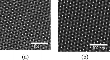 | ||
| Fig. 6 TEM images of (a) PB precursor and (b) PB-PPy-III. | ||
Finally, Fig. 7 shows the cyclic voltammogram of PB-PPy-III electrode in 1.0 M NaNO3 solution. It displays a typical stable redox couple (labelled A and B), which could be assigned to the PPy backbone. This clearly suggests that even though the deposited PPy film does not cover the pore walls completely, percolating PPy coating must exist, which explains the good electrochemical activity of the PB-PPy sample. The PB precursor is not conductive and does not show any electroactivity. This suggests that the PPy/NPM has a potential as a novel kind of nanoporous electromaterials.
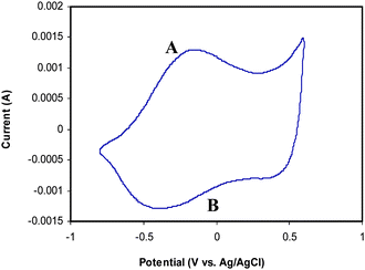 | ||
| Fig. 7 Cyclic voltammogram of PB-PPy-III. Range: −0.8 V to +0.6 V. Scan rate: 50 mV s−1. | ||
In conclusion, conducting PPy thin coatings on nanopores' surface of nanoporous PB were obtained by using vapor phase polymerization of pyrrole with ferric p-toluenesulfonate as oxidant. The highly ordered porous structure of PB precursor was preserved after modification as shown by SAXS and TEM. After incorporation of PPy coatings, previously insulating nanoporous polymers became electroactive and conductive as verified by cyclic voltammetry. The presented method provides a general approach for producing conductive nanoporous polymers, which have significant application potential as novel electrode materials with well-ordered nanoporous structures in both electrochemical and electronic devices.
Acknowledgements
FG acknowledges the financial support from the Danish Research Council for Technology and Production Sciences (FTP Grant No. 26-03-0271). We acknowledge Prof. G. Wallace's continuous support for this international collaboration as the Director of Intelligent Polymer Research Institute at Wollongong.Notes and references
- E. J. W. Crossland, M. Kamperman, M. Nedelcu, C. Ducati, U. Wiesner, D. M. Smilgies, G. E. S. Toombes, M. A. Hillmyer, S. Ludwigs, U. Steiner and H. J. Snaith, Nano Lett., 2009, 9, 2807 CrossRef CAS.
- D. H. Kim, Z. Sun, T. P. Russell, W. Knoll and J. S. Gutmann, Adv. Funct. Mater., 2005, 15, 1160 CrossRef CAS.
- B. J. S. Johnson, J. H. Wolf, A. S. Zalusky and M. A. Hillmyer, Chem. Mater., 2004, 16, 2909 CrossRef CAS.
- T. Bein and P. Enzel, Angew. Chem., Int. Ed. Engl., 1989, 28, 1692 CrossRef.
- M. Ikegame, K. Tajima and T. Aida, Angew. Chem., Int. Ed., 2003, 42, 2154 CrossRef CAS.
- R. Guo, G. Li, W. Zhang, G. Shen and D. Shen, ChemPhysChem, 2005, 6, 2025 CrossRef CAS.
- F. Guo, J. W. Andreasen, M. E. Vigild and S. Ndoni, Macromolecules, 2007, 40, 3669 CrossRef CAS.
- B. Winther-Jensen, J. Chen, K. West and G. Wallace, Macromolecules, 2004, 37, 5930 CrossRef CAS.
- S. Ndoni, M. E. Vigild and R. H. Berg, J. Am. Chem. Soc., 2003, 125, 13366 CrossRef CAS.
- The following equation can be used to calculate the average coating thickness of PPy on the pore walls: D (Å) = 104 × m/(s × dPPy) where D (Å) is the coating thickness in Å, m is the fractional mass uptake of PPy (can be read from Table 1), dPPy is the mass density (1.5 g cm−3) of PPy, and s is the specific surface area (270 m2 g−1) of nanoporous PB. The average coating thickness of PPy for sample PB-PPy-IV can be estimated as 0.5 Å by using the above equation.
Footnote |
| † Electronic supplementary information (ESI) available: Experimental details and Fig. S1 and S2. See DOI: 10.1039/c0py00322k |
| This journal is © The Royal Society of Chemistry 2011 |
