Organic-inorganic nanocomposites synthesized viaminiemulsion polymerization
Jing
Hu
ab,
Min
Chen
b and
Limin
Wu
*b
aSchool of Perfume and Aroma Technology, Shanghai Institute of Technology, Shanghai, 200235, China
bDepartment of Materials Science, Fudan University, Shanghai, 200433, China. E-mail: lmw@fudan.edu.cn
First published on 15th November 2010
Abstract
Miniemulsion polymerization, a kind of heterogeneous polymerization method, is being more and more used for synthesis of various novel organic-inorganic hybrid materials. In this review, we would seek to highlight the recent development of organic-inorganic nanocomposites synthesized viaminiemulsion polymerization. The examples demonstrate that the inorganic nanoparticles, such as oxide magnets, clays, carbon, silica, titanium dioxide, etc., can be embedded inside the polymers or as armor on the surfaces of polymer particles viaminiemulsion polymerization to form organic-inorganic nanocomposites with various morphologies.
 Jing Hu | Jing Hu received her PhD degree from Shaanxi University of Science and Technology in July, 2009. Then she joined School of Perfume and Aroma Technology of Shanghai Institute of Technology as a lecturer in perfume and aroma technology. In 2010, she was awarded “Shanghai Chenguang Scholar” by Shanghai municipality. Her current research interests include preparation and assembly of nanocapsules, function mechanism of sustained fragrance and propagation fibers. |
 Min Chen | Min Chen received her PhD degree from Fudan University under the supervision of Professor Limin Wu in 2006. Her dissertation was chosen as one of “Top 100 National Excellent Doctoral Dissertation” in 2008. Just after finishing the doctorate work, she joined the Department of Materials Science, Fudan University, and was successively awarded “Shanghai Chenguang Scholar” and “Rising Star” by Shanghai municipality. She is currently Associate Professor. Her research interests include the synthesis, characterization, assembly and properties of novel organic-inorganic hybrid nanostructured materials and inorganic hollow spheres. |
 Limin Wu | Limin Wu received his PhD degree from Zhejiang University in 1991. He worked as lecturer then associate professor from 1991 to 1994. He worked as visiting professor at Pennsylvania State University and Eastern Michigan University from 1994 to 1999. He joined Fudan University in 1999, where he currently is “Changjiang Scholar” Professor awarded by the Ministry of Education of China. His current research interests include synthesis, assembly and photoelectric properties of organic-inorganic nanoparticles, hollow inorganic particles, development of functional coatings and films. |
1. Introduction
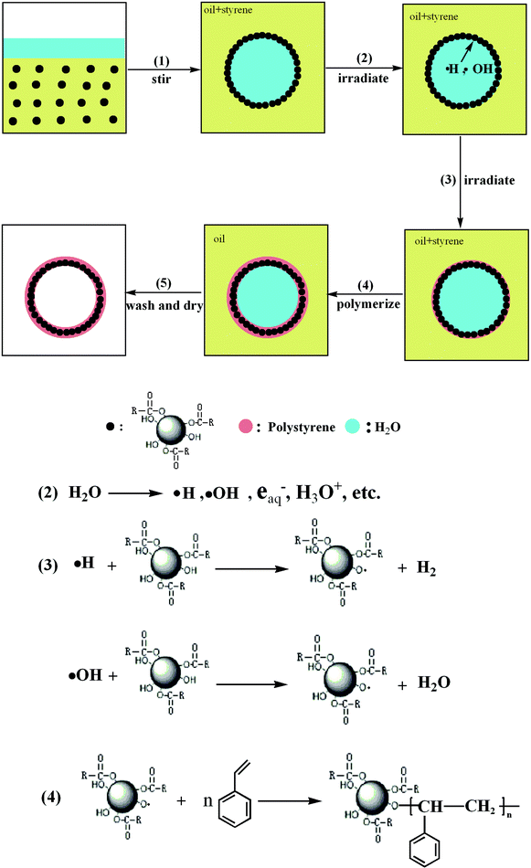
Nowadays, it has been recognized that organic-inorganic nanocomposites are very important materials for photonic crystals, coatings, adhesives, pharmaceutical, biomedical and cosmetic formulations.1–8 Many heterogeneous polymerization techniques such as emulsion polymerization,9,10dispersion polymerization,11,12microemulsion polymerization,13,14miniemulsion polymerization, etc., have been used to synthesize polymer-inorganic nanocomposites. Among them, emulsion polymerization is the most frequently used method. In this process, monomer is dispersed in an aqueous solution of surfactant with a concentration exceeding the critical micelle concentration and polymerization is carried out by means of an (most often water-soluble) initiator system. However, during the traditional emulsion polymerization, the polymer particles can be formed either by entry of radicals into the micelles (heterogeneous nucleation), and/or precipitation of growing oligomers in the aqueous phase (homogeneous nucleation), and/or radical entry in monomer droplets.15 Therefore, it is very tough to control the structure, morphology and size of nanocomposite spheres, especially to encapsulate inorganic nanoparticles inside polymer shells. And some complicated parameters, e.g., electronegativity, polarity, group interaction of inorganic nanoparticle–water (solvent)–polymer, have an important impact on the size and stability of nanocomposite spheres.To work out these problems, miniemulsion polymerization has been used to synthesize organic-inorganic nanocomposites more in recent years. It involves the use of an effective surfactant/costabilizer system to produce very small monomer droplets (0.01–0.5 μm). The droplet surface area in this system is very large, and most of the surfactant is adsorbed at the droplet surface. Particle nucleation is primarily via radical (primary or oligomeric) entry into monomer droplets, since little surfactant is present in the form of micelles, or as free surfactant available to stabilize particles formed in the continuous phase. Thus, in comparison with emulsion polymerization, the numbers and sizes of polymer particles in miniemulsion polymerization can be controllable, since the reaction proceeds by the polymerization of monomers in these small droplets and one monomer droplet leads to one polymer particle.16,17 And this monomer droplets nucleation of miniemulsion polymerization can provide more efficient encapsulation of inorganic nanoparticle. Generally, the formation of polymer-inorganic nanocomposite viaminiemulsion polymerization has three steps, two dispersion steps and one polymerization step (Fig. 1), and some interesting reviews on the structures of nanoparticles and nanocapsules have been presented recently.18,19 In this paper, we review the recent development of miniemulsion polymerization for syntheses of polymer-inorganic nanocomposites, from the classificatory angle of materials.
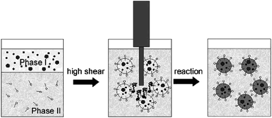 | ||
| Fig. 1 A schematic of the process of miniemulsion polymerization. Reprinted with permission from ref. 19. Copyright 2009 Wiley-VCH. | ||
2. Magnetic nanoparticles-based nanocomposites
Magnetic nanoparticles-based nanocomposites have been paid a lot of attention because of their superparamagnetic properties and potential applications, e.g., purification and concentration of proteins20 and viruses,21 contrast agents in magnetic resonance imaging, mediators in hyperthermia, and carriers for guided drug delivery.22,23In most of the envisaged applications, the magnetic particles perform the best when their sizes are below a critical value, which is dependent on the material but typically around 10–20 nm. Thus each nanoparticle becomes a single magnetic domain and shows superparamagnetic behavior when the temperature is above the so-called blocking temperature. Such individual nanoparticles have a large constant magnetic moment and behave like giant paramagnetic atoms with a fast response to applied magnetic fields with negligible remanence (residual magnetism) and coercivity.24 So the successful application of such magnetic nanocomposites in the areas listed above is highly dependent on the stability of the particles under a range of different conditions. Many approaches have been employed to stabilize the magnetic particles during or after the synthesis, including emulsion polymerization,25,26dispersion polymerization27 and miniemulsion polymerization.28 Generally, the magnetic nanocomposites can be obtained successfully by the three-step process involving two dispersion steps and one miniemulsion polymerization step.29–31 First, magnetic nanoparticles are dispersed in the monomer phase with the aid of stabilizer,32 second, the monomer phase and the aqueous phase are mixed by a dispersion device with a high shear force and sonication to prepare the miniemulsion containing the monomer droplets with diameters of 10–500 nm; and, third, miniemulsion polymerization is carried out. For example, Ramirez and Landfester 29,30 reported that magnetite nanoparticles (10 nm) were formed by precipitation from a ferrous and ferric chloride solution and hydrophobized by oleic acid.33 The hydrophobized magnetic nanoparticles were then dispersed in octane and miniemulsified in water with sodium dodecyl sulfate (SDS) as the surfactant. After evaporation of octane, the SDS stabilized magnetite was added to a monomeric miniemulsion. By sonication the aggregates and the monomer droplets were merged and the droplets containing monomer and the magnetite aggregates could subsequently be polymerized, resulting in polymeric nanocomposites containing magnetic particles. In this way, up to 40 wt% magnetite could be encapsulated resulting in polystyrene with a high homogeneity of the magnetite content. However, the presence of the oxidizing initiator fragments might lead to the loss of magnetization. In fact, some polymerization factors such as initiator type, concentration of surfactant and dose of monomers also influence the morphologies and properties of magnetic nanocomposite.28–32 For example, when the water-soluble persulfate initiator was used, 300 nm magnetic nanoparticles with uniform dispersion was obtained; when oil-soluble 2, 2′-azobiisobutyronitrile (AIBN) was used instead of potassium persulfate, magnetite nanoparticles under 100 nm were located on the outer layer of nanocomposite spheres.34
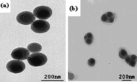
With the more applications of the magnetic nanocomposite spheres in biomedical fields, the magnetic nanocomposite spheres still need to be surface-functionalized.32,35–41 For example, Xu et al.41 prepared the epoxy group-functionalized magnetic polymer latex consisting of a superparamagnetic core coated with a polymeric shell by modified miniemulsion polymerization, and controlled the epoxy group density on the surface by a further seed polymerization. With the increasing divinyl benzene (DVB) content in the monomer mixture, the thickness of shell structure increased accordingly (Fig. 2).The suspension dispersibility of the magnetic nanocomposite spheres could be also improved by the help of the shell structure.
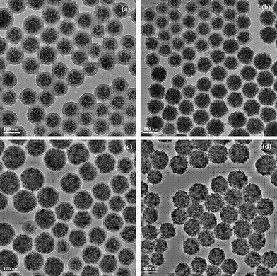 | ||
| Fig. 2 TEM images of the influence of different DVB contents on the morphology of the magnetic particle latex. a 0.75 g, b 0.5 g, c 0.2 g, d 0 g. Reprinted with permission from ref. 41. Copyright 2010 Wiley-VCH. | ||
In the miniemulsion polymerization process, surfactant is used in sufficient quantity to provide the droplets with colloidal stability against coalescence. In order to avoid the migration of surfactants, emulsifier-free miniemulsion polymerization was used to obtain the encapsulation of magnetite nanoparticles into polystyrene particles or the magnetic crosslinked polystyrene-co-chloromethylstyrene latex particles with 2,2′-azobis (2-amidinopropane) dihydrochloride as a cationic and ionizable water-soluble initiator.42–44 However, the presence of this ionizable initiator would affect the miniemulsion stability, polymerization rate and final molecular weight. Therefore, there is a need to investigate new approaches with the use of water-insoluble monomers. For example, Forcada and co-workers45 synthesized the self-stabilized magnetic polymeric nanocomposites by emulsifier-free miniemulsion polymerization using styrene as a monomer, sodium-p-styrenesulfonate as an ionic comonomer, hexadecane as a hydrophobe, and AIBN as an initiator in the presence of hydrophobic magnetite particles. The sulfonic groups of sodium-p-styrenesulfonate anchored covalently onto the particle surface avoid the migration occurring with conventional emulsifier molecules, enhance the stability of particles and increase the hydrophilicity of the copolymer with respect to the encapsulated oleic acid-coated magnetite particles. Moreover, this also favors the concentration of magnetite particles dispersed in the core of composite particles.
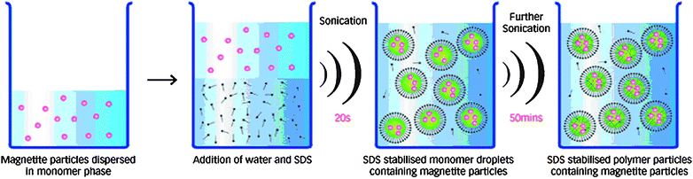
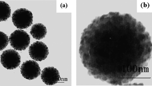
Another novel and interesting technology of ultrasonic induced miniemulsion polymerization can predigest the conventional three-step process, and the fast rate and relatively high percentage of monomer to polymer conversions can be achieved without use of chemical initiators at low reaction temperature.46–50 For instance, Hatton and co-workers47 developed a one-pot method of preparing poly(n-butylmethacrylate) latex beads loaded with a high content of magnetite nanoparticles (Fig. 3), using the schematic process in Fig. 4. The hydrophobic Fe3O4 nanoparticles were dispersed in n-butyl methacrylate by stirring in a reaction vessel. A water-continuous miniemulsion was prepared by adding water with SDS as the dispersant to the nanoparticle/monomer dispersion. After the mixture deaerated by bubbling with argon, the liquid mixture was then subjected to sonication to generate a uniform miniemulsion. The polymerization reaction was commenced by subjecting the emulsion mixture to continuous sonication without using any initiator. In this way, approximately 120 nm poly(n-butylmethacrylate) latex beads including 50 magnetite particles per polymer particle was obtained. Besides, the oxidation state of the magnetite particles was not affected by the polymerization reaction. The nanocomposite spheres were superparamagnetic with a saturated magnetization of 24 emu/g, superior to the 10–20 emu/g saturation values given for commercially available magnetic nanoparticles.
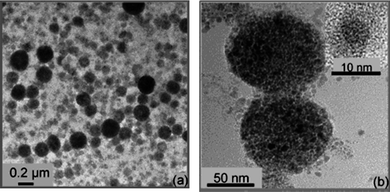 | ||
| Fig. 3 TEM images of the encapsulation of magnetite nanoparticles in polymer latex spheres at different magnifications. Reprinted with permission from ref. 47. Copyright 2009 American Chemical Society. | ||
 | ||
| Fig. 4 A schematic of the process for magnetite nanocomposite spheres preparation by the sonochemically driven miniemulsion polymerization. Reprinted with permission from ref. 47. Copyright 2009 American Chemical Society. | ||
The hydrophilic magnetic nanocomposite spheres can also be synthesized via inverse miniemulsion polymerization with water-based magnetic ferrofluid as dispersed phase and organic solvent and monomers as continuous phase.51–53 For example, to synthesize the thermoresponsive and superparamagnetic hydrogel microspheres based on poly(N-isopropylacrylamide) (PNIPAAm), poly (acrylic acid) oligomers were used as stabilizers to produce a stable water-based Fe3O4 ferrofluid, which could mix well with the water-soluble monomers. Then, poly(NIPAAm-co-methacrylic acid)/Fe3O4 composite latex particles were synthesized with ammonium persulfate/sodium metabisulfite as the redox initiatorvia W/O miniemulsion polymerization.53 Moreover, W/O miniemulsion polymerization can be used as one approach to synthesize the hollow superparamagnetic nanocomposite spheres between 184 and 522 nm at room temperature and under ambient pressure without hard templates. More surfactant leads to the smaller size and narrower size distribution for the emulsion polymerization system (Fig. 5). According to the schematic process in Fig. 6, the magnetic nanoparticles tended to assemble at the interface of water and oil phase because of their amphipathicity. When the inverse miniemulsion was irradiated by γ-ray, many active intermediates were generated owing to the radiolysis of water. As these radicals tried to enter into the oil phase, they first met the active hydroxyl groups at the surfaces of the magnetic particles located at water/oil interface and abstracted hydrogen from them, leading to the formation of free radicals at the surfaces of magnetic particles. Therefore, the polymerization would be carried out at the surfaces of nanoparticles to form the hollow magnetic nanocomposite microspheres.54
 | ||
| Fig. 5 TEM and SEM images of the morphology of the hollow magnetic spheres with different sorbitan monooleate content. a 0.27 g; b, d 0.46 g; c, e 0.92 g. Reprinted with permission from ref. 54. Copyright 2008 Wiley-VCH. | ||
 | ||
| Fig. 6 A schematic illustration of hollow superparamagnetic nanocomposite microspheres. Reprinted with permission from ref. 54. Copyright 2008 Wiley-VCH. | ||
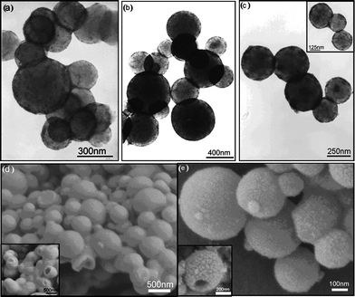
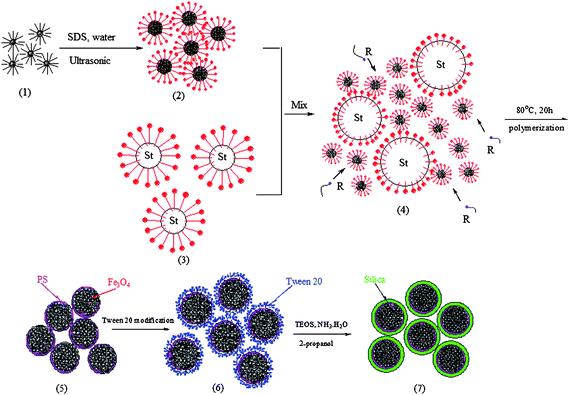
Gu and co-workers55 developed a new process combining modified miniemulsion/emulsion polymerization with sol–gel technology to prepare monodisperse, nanoscale, superparamagnetic Fe3O4/polystyrene/silica nanospheres, using the schematic preparation process in Fig. 7. The ferrofluid coated with oleic acid was added to the aqueous solution with SDS and treated ultrasonically to obtain miniemulsion A. The miniemulsion A was mixed with another miniemulsion B made of styrene monomer droplets to obtain a double-miniemulsion system. This double-miniemulsion system was carried out to form polystyrene/Fe3O4 nanospheres. Then the as-synthesized superparamagnetic polystyrene/Fe3O4 nanospheres were modified by polyoxyethylene (20) sorbitan monolaurate for dispersing the hydrophobic nanospheres into an aqueous phase. At last, polystyrene/Fe3O4 nanospheres were coated with a silica layer via a modified Stöber process. Through this technique, monodisperse, well proportioned spherical Fe3O4/polystyrene/silica nanospheres (105 nm) were obtained. 10 nm Fe3O4 crystals were randomly embedded in the polymer matrix and the outer silica-outing layer was quite uniform (Fig. 8). The saturation magnetization value of Fe3O4/polystyrene/silica nanospheres decreased with increasing shell thickness due to the decrease of the magnetite fraction in each microsphere.
 | ||
| Fig. 7 A diagram of the preparation of hydrophilic magnetic Fe3O4/polystyrene/silica nanospheres with high saturation magnetization. Reprinted with permission from ref. 55. Copyright 2006 American Chemical Society. | ||
 | ||
| Fig. 8 TEM images of polystyrene/Fe3O4 nanospheres (a, b) and silica-coated magnetic polystyrene/Fe3O4 nanospheres (c, d). Reprinted with permission from ref. 55. Copyright 2006 American Chemical Society. | ||
Compared to other polymerization methods with low encapsulation of magnetic nanoparticles, e.g., less than 25% for suspension polymerization and dispersion polymerization, and even less than 10% for emulsion polymerization, miniemulsion polymerization can provide more than 45% and even as high as 80% magnetic nanoparticle content in the nanocomposite spheres.55
3. Clay-based nanocomposites
Since the Toyota research team56 reported that the exfoliated Nylon 6/clay nanocomposite was prepared via in situpolymerization of e-caprolactam, more and more polymer/clay nanocomposites have found their applications in cosmetics, pharmaceuticals, catalysis, optics, agriculture, coating and painting areas.57–59 In comparison with the pure polymers, the polymer/clay nanocomposites exhibit many excellent properties such as enhanced mechanical and thermal properties, reduced gas permeability, high fire resistance and lower flammability.60–62 Up to now, three major preparation categories of polymer/clay nanocomposites have been reported: intercalation of the polymer or pre-polymer from solution, melt intercalation and in situ intercalative polymerization, in which in situ intercalative polymerization is more versatile due to variety of polymerization conditions and clay treatments and thus is a promising way to produce tailored nanocomposites with controlled morphology.63 The platelet-shaped clay are made of two-dimensional 1 nm layers of an aluminate sheet sandwiched between two silicate sheets.64 The key issue is the exfoliation of clay to the level of individual platelets through nanocomposites. The hydrophilic clay platelets can be organically modified by exchanging the metal ions with ammonium salts as vinylbenzyl trimethylammonium chloride (VBTAC), cetyltrimethyl ammonium chloride,65,66cetyltriethylammnonium bromide (CTAB),67,68 or 2-methacryloyloxyethyl hexadyldimethyl ammonium bromide (MA16),69 to improve the uniform dispersibility.Polymer/clay nanocomposites prepared viaminiemulsion polymerization can be divided into three structures: irregular dispersion of exfoliative clay in polymer matrix, clay armored polymer particles and clay encapsulated inside the polymer particles. For example, Leiza and co-workers successfully synthesized a series of high content waterborne acrylic copolymer/clay nanocomposites using commercial organically modified clays,67,68 or montmorillonite clays exchanged with MA16.69 The commercial organically modified clay was uniformly dispersed into polymer matrix with 42 wt% solid content by some exfoliated platelets as shown in Fig. 9. These modified clays containing hydroxyl groups offered a good compatibility with acrylic copolymer so that the copolymer can penetrate into the interlayer spaces. Recently, they still compared both commercial organically modified clays and MA16 modified montmorillonites, and showed that the latter ones were more compatible with the monomer system used for waterborne adhesives and hence allowed some platelets to be encapsulated in contrast with the armored structures found with the less compatible commercial ones. Moreover, they also discussed by means of Monte Carlo simulations the more probable location of the clay platelets depending on the interfacial tensions of the clay with the aqueous phase and the monomer phase, as well as the length/thickness ratio and the monomer droplet diameter.70,71
 | ||
| Fig. 9 TEM images of acrylic copolymer/clay nanocomposite latex films at different magnifications: 2 wt% commercial organically modified clay. Reprinted with permission from ref. 67. Copyright 2008 Wiley-VCH. | ||
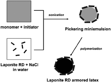
Stefan et al.72,73 prepared Laponite clay aromored latex particles of polystyrenevia a Pickering stabilized miniemulsion polymerization of monomer filled Laponite colloidosomes of submicron dimensions using a process as shown in Fig. 10. The Laponite RD was first dispersed in an aqueous solution of NaCl using sonication. Dimethyl-2,2′-azobis(isobutyrane) and hexadecane were then dissolved in styrene, and subsequently mixed with the clay dispersion. A stable Pickering miniemulsion of Laponite colloidosomes was generated viasonication. At last, the polystyrene latex particles with a mean diameter of 145 nm, armored with Laponite RD clay particles were obtained (Fig. 11).
 | ||
| Fig. 10 Synthesis of Laponite RD armored polystyrene latex via Pickering miniemulsion polymerization. Reprinted with permission from ref. 72. Copyright 2005 American Chemical Society. | ||
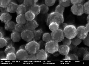 | ||
| Fig. 11 FE-SEM image of Laponite RD armored polystyrene latex. Reprinted with permission from ref. 72. Copyright 2005 American Chemical Society. | ||
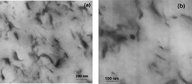
The real breakthrough advantage of miniemulsion polymerization over conventional emulsion polymerization is the fact that clays can be effectively encapsulated in the polymer particles.74–78 For instance, Faucheu et al.74 adopted two new synthetic routes to obtain two different nanostructures of clay/polymer nanocomposites. In Route I, clay-armored polymer particles were obtained through miniemulsion polymerization by anchoring a free initiator to the clay surface through cation exchange. This treatment renders the clay particles amphiphilic and promotes subsequent clay interaction with the miniemulsion droplets. The clay with attached radicals nucleates the nanodroplets that progressively form particles consisting of an outer shell of clay sheets surrounding an inner polymer core (C-samples, Fig. 12a). In Route II, an organosilane coupling agent, g-methacryloxypropyltrimethoxysilane (g-MPTMS) was grafted to the Laponite rims, thus the Laponite platelets present a good compatibility with the monomers, they are expected to remain inside the monomer droplets and be therefore inside the polymer particles (D-samples, Fig. 12b). The film formed from those composite nanoparticles presented very different nanostructures. The first series of nanocomposite materials presented a network of Laponite able to percolate at higher clay contents, whereas interactions between clays were limited in the D samples due to their confinement inside the individual polymer particles. Large effects were observed on the mechanical properties. Due to the presence of interaction between clay particles in the C samples, high reinforcement factors were observed from ca. 3 vol% Laponite content whereas lower reinforcement was observed for the D samples. Moreover, due to the localization of stress at the Laponite edges in the C samples, mechanical damage occurred whereas the D samples exhibited a viscoelastic behavior similar to a blank polymer matrix.
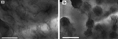 | ||
| Fig. 12 (a) A TEM image of sample C10%, (b) A TEM image of sample D5%. Thin films obtained by evaporating a drop of diluted suspension on a carbon coated grid. (JEOL 200CX, accelerating voltage 200 kev). Scale bar 200 nm. Reprinted with permission from ref. 74. Copyright 2010 Elsevier. | ||
Polymer/clay nanocomposite spheres can also be obtained via reversible addition fragmentation chain transfer (RAFT) miniemulsion polymerization. Use of the attached RAFT agents can minimize the exit problem of the R group to the aqueous phase, that is, there is little radicals exiting into the aqueous phase, and moreover, there is no phase separation when the RAFT agents are attached to clay platelets, due to little or no superswelling effect, thus close to monomodal polymer particle size distribution is achieved. Hartmann and co-workers79 first reported that the RAFT grafted montmorillonite (MMT) clays [e.g.N,N-dimethyl-N-(4-(((phenylcarbonothioyl)thio)methyl)benzyl)ethanammonium-MMT and N-(4-((((dodecylthio)carbonothioyl)thio)methyl)benzyl)-N,N-dimethylethanammonium-MMT] of various loadings were dispersed in styrene monomer and the resultant mixtures emulsified and sonicated in the presence of hexadecane into miniemulsions. The stable miniemulsions were polymerized to yield encapsulated polystyrene/clay nanocomposite spheres. The nanocomposites were of partially exfoliated morphology at low clay loadings, and changed to intercalated morphology as the clay loading increased.
Besides this, miniemulsion polymerization through an anionic reaction pathway was successfully used to encapsulate a montmorillonite clay within a fluorinated cyclotrisiloxane. 1,3,5-Tris(trifluoropropylmethyl)cyclotrisiloxane was directly added into the aqueous suspension of MMT with the cationic surfactant (didodecyldimethylammonium bromide) and the commercially nonionic surfactant and then mixed under vigorous mechanical stirring. Then, this miniemulsion polymerisation was carried out. In this way, a novel poly(trifluoropropylmethyl)siloxane encapsulated montmorillonite hybrid system with up to 5 wt% clay loading in the form of a water dispersion was developed.80
Compared to emulsion polymerization which generally yields the nanostructure of clays covering the surface of polymer particles rather than clay encapsulation, the significant contribution of miniemulsion polymerization for clay-based nanocomposites is it can synthesize composite nanoparticles with tailored morphologies: the clay platelets either covering the surface of the polymer particles or being embedded inside the polymer particle.
4. Carbon nanotube-based nanocomposites
It is well known that carbon nanotubes (CNTs) have unique flexibility, chemical stability, and electrical conductivity,81–84 due to their high ratio of length to diameter and the π–π connections between adjacent carbons, thus have several potential applications, such as field emitters,85 nano-electronic devices,86,87probe tips for scanning probe microscopes,88 and reinforcing fillers for polymer composites.82,83When used into polymers, small polymer sizes, surfactants and hydrophobes in miniemulsion polymerization can provide the advantages for the dispersion of carbon nanotubes by the encapsulated polymer.89 During the miniemulsion polymerization, it is crucial to make the monomeric materials spread on the nanotube surface as soon as possible. The dispersion of single-wall-nanotubes (SWNTs) is dependent on the surfactant types, e.g. the cationic surfactant (CTAB),90 the combination of an anionic and a non-ionic surfactant (SDS and ethoxylated alkylphenol),91 or the combination of a cationic and an anionic surfactant (CTAB and SDS) or the anionic surfactant alone.92 For example, Resasco and co-workers90 reported that the stable miniemulsion was firstly formed by emulsifying a hydrophobic monomer under high shear (ultrasonication) conditions with the aid of a cationic surfactant (CTAB) together with purified carbon nanotubes. Then, the polymerization inside the microdroplets was readily achieved by a combination of acid-catalyst seeding (polystyrene-AlCl3) and oil soluble initiator at relatively mild temperatures. Incorporation of the nanotubes inside the polymeric matrix brought about physical changes such as a strong black coloration, as well as a substantial drop in the electrical resistivity from values greater than 1016 Ω cm for the unmodified polymer down to 106 Ω cm in the polystyrene/SWNTs composites with 8.5 wt% of nanotube loading.
Chung and co-workers93 presented a kind of higher electrical conductivity polypyrrole/SWNT nanocomposites via in situminiemulsion polymerization. The purified SWNTs were dispersed with SDS as a surfactant and 1-pentanol as a hydrophobe in deionized water and then sonicated for 10 h. Pyrrole and DVB used as a monomer and a cross-linking agent were added into the dispersed solution. Then, the miniemulsion polymerization was carried out, producing three different morphologies, as shown in Fig. 13: (A) SWNT surfaces attached with spherical shape polypyrrole of about 50 nm diameter, (B) bare surface of SWNT, and (C) the SWNT surfaces covered with thin film of polypyrrole. A large proportion of polypyrrole attached on SWNT surfaces had the structure ‘A’. The polypyrrole showed 0.0177 S cm−1 of electrical conductivity. The conductivity of nanocomposites increased sharply until the amount of SWNTs reached 8.7 wt% in polypyrrole/SWNT nanocomposites. When the weight fraction of SWNTs was 29.25 wt%, the conductivity was 6.25 S cm−1.
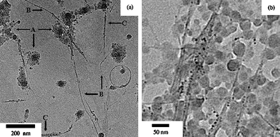 | ||
| Fig. 13 TEM images of polypyrrole/SWNT nanocomposites at different magnifications. Reprinted with permission from ref. 88. Copyright 2005 Elsevier. | ||
Besides the above properties, polymer/carbon nanotube nanocomposites still have excellent tribological properties. Xin and co-workers91 prepared the polystyrene/carbon nanotube nanocomposites with a morphology of the CNTs locked the polymer nanoballs into a chain as shown in Fig. 14. These novel structural composites would possess high interfacial bonding strength and good dispersion capability. As an additive, it would improve the lubricating performance of the base fluid by way of a roller bearing effect between the two rubbing surfaces. In general, relative to other organic-inorganic nanocomposites, the carbon nanotube-based nanocomposites prepared from miniemulsion polymerization were not investigated extensively. How to acquire monodisperse morphology and how to make directional alignment of carbon nanotubes in polymers remain great challenges, in order to efficiently improve the performance of polymers or endow novel properties.
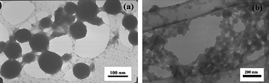 | ||
| Fig. 14 TEM and SEM images of polystyrene/CNT nanocomposites: (a) TEM, (b) SEM. Reprinted with permission from ref. 91. Copyright 2007 Elsevier. | ||
5. Silica-based nanocomposites
Nanosilica is the most frequently used nanoparticle for fabrication of organic-inorganic nanocomposites due to its cheap, chemically inert and optically transparent properties,94,95 and the extensive applications in plastics, rubbers, coatings, etc.96–98The grafting of methacryloxypropyltrimethoxysilane (MPS) onto silica particles is an effective way of improving the encapsulation efficiency of silica particles in the miniemulsion droplets and in the resultant composite latex spheres. Bao and co-workers99 synthesized acrylate polymer/silica nanocomposite spheres using the mixture of the MPS-modified silica and acrylate monomers, as shown in Fig. 15. When 0.10 g MPS/g based on silica was used to modify silica, the encapsulation efficiency of silica was greater than 95 wt%, and the degree of grafting of acrylate polymer onto silica was about 60 wt%.
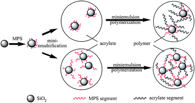 | ||
| Fig. 15 Formation of the grafted and crosslinked polymer chains in miniemulsion polymerization of acrylate monomers in the presence of MPS modified silica particles. Reprinted with permission from ref. 99. Copyright 2006 Elsevier. | ||
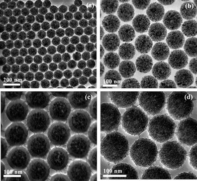
Wu et al.95,100,101 reported that different morphologies of polymer/silica nanocomposite spheres can be obtained by miniemulsion polymerization in the presence of MPS modified silica nanoparticles. By adjusting the silica nanoparticles size and the surfactant concentration, the size and morphology of nanocomposite spheres can be tuned.95 For 45 nm silica particles, the size of the nanocomposite spheres decreased from 200 to 80 nm with increasing surfactant concentration from 20 to 40 mM, and the numbers of silica particles entrapped into each polymer particle gradually decreased and finally formed core-shell morphology. For 90 nm silica particles, the size of the nanocomposite spheres also decreased from 180 to 130 nm with increasing surfactant concentration from 20 to 40 mM, but the core-shell morphology was kept unchanged. For 200 nm silica particles, some “raspberry-like” morphology was observed (Fig. 16). Furthermore, a series of poly(styrene–butyl acrylate)/silica nanocomposite spheres with various morphologies (e.g., multicore–shell, normal core–shell) were prepared viaminiemulsion polymerization.100 The incorporation of butyl acrylate into the polymer was useful for a multicore–shell morphology in comparison with only a hard monomer in the polymer (Fig. 17). Increasing the particle size of silica or decreasing the emulsifier content tended to form a normal core–shell or even raspberry-like structure. And raspberry-like silica/polystyrene/silica multilayer nanocomposite spheres with larger silica as the core and smaller silica as the shell were synthesized viaminiemulsion polymerization (Fig. 18).101
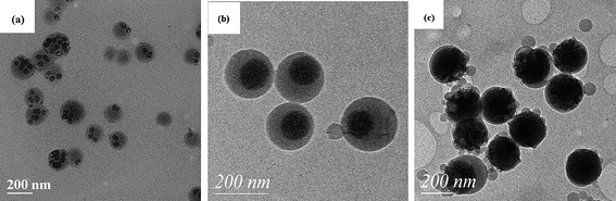 | ||
| Fig. 16 TEM photographs of polystyrene/silica nanocomposite spheres using different silica contents: (a) 45 nm silica; (b) 90 nm silica; (c) 200 nm silica. Reprinted with permission from ref. 95. Copyright 2005 American Chemical Society. | ||
 | ||
| Fig. 17 TEM photographs of poly(styrene–butyl acrylate)/silica nanocomposite spheres using 20 mM SDS and 90 nm silica at different styrene/butyl acrylate weight ratios: (a) 10/0; (b) 6/4. Reprinted with permission from ref. 100. Copyright 2006 Wiley-VCH. | ||
 | ||
| Fig. 18 TEM images of the raspberry-like, double-decked silica/polystyrene/silica hybrid spheres at different magnification. Reprinted with permission from ref. 101. Copyright 2007 Wiley-VCH. | ||
Silica nanoparticles partially surface modified with n-octadecyltrimethoxysilane can be used to prepare asymmetric polymer/silica nanocomposite spheres. Xu et al.102 first reported that asymmetric nanocomposite spheres pairs of polystyrene and silicavia one-step miniemulsion polymerization. The silica nanoparticles after modification behave amphiphilic. The W/O-silica particles are dispersed into a monomer containing styrene and hexadecane to form the oil phase. SDS and sodium bicarbonate were dissolved in deionized water to form the water phase. Then, the oil and water phases are miniemulsified by ultrasonication. The asymmetrical compound droplets are formed with a monomer droplet partially linked on the silica surface as a result of strong hydrophobic interaction between the monomer molecules and the modified area of the silica surface. Then the droplets are initiated by water-soluble initiator potassium persulfate and reacted to form asymmetric polystyrene/silica nanocomposite spheres (Fig. 19).
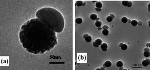 | ||
| Fig. 19 TEM images of mushroom-like polystyrene/silica nanocomposite spheres: (a) single pair; (b) multiple pairs. Reprinted with permission from ref. 102. Copyright 2008 American Chemical Society. | ||
On the other side, if silica nanoparticles are not functionalized, the negatively charged silica particles would be used as Pickering stabilizers, leading to a variety structure of polymer/silica nanocomposite spheres, and the size of polymer/silica nanocomposite spheres is mainly controlled by the amount and the variety of surfactants. The addition of cationic surfactant cetyltrimethylammonium chloride can improve the coupling of latex and silica nanoparticles because of the electrostatic interactions. The anionic surfactants applied under basic conditions can assist the dispersion stability of nanoparticles, but cannot improve the incorporation of silica nanoparticles.103 Generally, the incorporation of the anionic surfactants causes raspberry-like composite microspheres with polystyrene cores and silica shell through miniemulsion polymerization.104,105 For example, Chen and co-workers104 synthesized raspberry-like composite microspheres with polystyrene cores and silica shell by using the anionic SDS as a surfactant and 2-(methacryloyl) ethyltrimethylammonium chloride (MTC) as the auxiliary monomer. Since the surface of silica particle is negatively charged, the cationic surfactant is always indispensable for obtaining polystyrene/silica composite particles through electrostatic interaction between the cationic surfactant and silica particles. The reason why anionic surfactants can also generate nanocomposite spheres is attributed to the electrostatic interaction between the MTC and silica particles, which suppresses the repulsive force between SDS and silica particles.
The combination of miniemulsion polymerization and sol–gel method provides a one-step way to synthesize polymer/silica nanocomposite spheres, avoiding the hydrophobic modification and redispersion of inorganic particles. Theoretically, the hydrolysis and condensation of tetraethyl orthosilicate (TEOS) with water alone is very slow, so an acidic or basic catalyst is usually needed. However, during the combination of miniemulsion polymerization and sol–gel method, the polymerization temperature is usually much higher than that of the traditional sol–gel process. This can enhance the hydrolysis and condensation rate of TEOS, causing the core-shell structure of polymer/silica nanocomposite spheres to form without any catalyst.106 Nevertheless, asymmetric polymer/silica nanocomposite spheres can also be obtained by this method. The key issue in obtaining this asymmetric nanocomposite sphere is the combination of miniemulsion polymerization and the local surface modification of silica particles. Wu and co-workers107 obtained polystyrene/silica asymmetric hybrid spheres in one step by miniemulsion polymerization and sol–gel method as the process displayed in Fig. 20. Compared with other methods to fabricate asymmetric hybrid spheres, this strategy is facile and effective: neither the preparation of templates beforehand nor the complicated modification of templates is necessary. Moreover, the size of polystyrene particles in asymmetric dimer spheres could be adjusted easily either by changing the weight ratio of styrene to TEOS or by altering sonication power during the miniemulsion preparation. After functionalization of the as-prepared asymmetric dimers by surface decoration with Ag particles, the spheres displayed the enhanced surface-enhanced Raman scattering properties. Boutti et al.108 successfully encapsulated silica nanoparticles into a polyamide membranevia an original process of interfacial polycondensation in a miniemulsion in a double emulsion. The 3-aminopropyl triethoxysilane coupling agent was grafted onto the surface of the silica nanoparticles, then direct miniemulsions were prepared from the microemulsion containing the functionalized silica nanoparticles, and the polycondensation between sebacoyl chloride and hexamethylenediamine occurred at the surface of the nanodroplets. The resulting silica/polyamide nanocomposite particles presented a mean diameter around 200 nm. These results showed that the interfacial polycondensation in miniemulsion could extend the range of processing strategies leading to the formation of organic-inorganic nanocomposites.
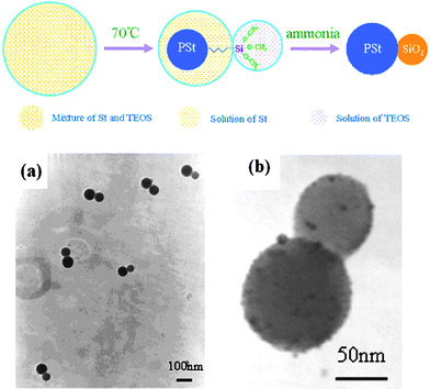 | ||
| Fig. 20 A schematic of the process for synthesis of polystyrene/silica asymmetric spheres viaminiemulsion polymerization and TEM images of asymmetric hybrid spheres: (a) hybrid polystyrene/silica asymmetric spheres, (b) hybrid polystyrene/silica asymmetric spheres decorated with Ag colloids. Reprinted with permission from ref. 107. Copyright 2008 Elsevier. | ||
Since silica nanoparticles are cheap, easily surface-modified and monodisperse, they are frequently used as models to synthesize organic-inorganic nanocomposite spheres except endowing limited properties of polymer matrix. Further functionalization of post-treatment of silica-based nanocomposite spheres with other organic or inorganic components are usually needed.
6. Titanium dioxide-based nanocomposites
Titanium dioxide (TiO2) is usually applied in coatings, plastics and papers, because it has a high refractive index and possesses the ability to reflect and refract or scatter light more effectively than any other pigments. In addition, it is a well-known photocatalyst for degradation of organic pollutants, medical treatment and microorganism photolysis.109–111Just like other inorganic nanoparticles, TiO2 nanoparticles are hydrophilic and easily aggregate, so they also need to be surface-modified. El-Asser and co-workers112–114 modified TiO2 nanoparticles first with polybutylene succinimide diethyl triamine and then dispersed 5 wt% of the hydrophobized particles in styrene prior to the miniemulsion process, about 89 wt% of TiO2 could be encapsulated in polystyrene. The average particle size increased from 97 nm for the unencapsulated polystyrene particles to 322 nm when TiO2 was encapsulated, while the mean size increased from 90 nm for the unencapsulated poly(styrene-butyl acrylate) latex to 351 nm for the TiO2 encapsulated polymer. This increase was attributed to the increasing numbers and sizes of the TiO2 particles encapsulated in each particle.115
Besides the encapsulation of TiO2 inside polymer particles, TiO2 nanoparticles can also be coated on the surfaces of polymer particles viaminiemulsion polymerization. Incorporation of acrylic acid as a comonomer can increase the interaction between TiO2 and polymer cores, and addition of a hydrophobic agent effectively prevents monomer diffusing into the aqueous phase.116 Chen et al.117 successfully synthesized polystyrene/TiO2 nanocomposite spheres by miniemulsion technique with both organic monomer and inorganic precursor trapped in the miniemulsion droplets (Fig. 21). First, the O/W miniemulsion with oil composed of acetylacetone chelated tetra-n-butyl titanate (TBT) and styrene were prepared. The oil droplets were stabilized by cationic surfactant CTAB and co-stabilizer hexadecane, thus the oil droplets were positively charged since CTAB was adsorbed on the surfaces. Then, the polymerization of styrene and the sol–gel reaction of TBT occurred inside the miniemulsion droplets, directly causing polystyrene/TiO2 nanocomposite spheres. The hydrophilic TBT diffused to the O/W interface during the polymerization of styrene and the TiO2 particles formed via the hydrolysis and condensation of TBT were successfully adsorbed onto the surfaces of the polymer particles through electrostatic interaction.
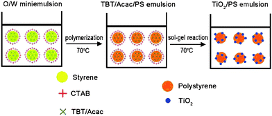 | ||
| Fig. 21 The formation of polystyrene/TiO2 nanocomposite in one step. Reprinted with permission from ref. 117. Copyright 2010 Elsevier. | ||
In order to fabricate multifunctional nanocomposite spheres, two different inorganic cores can be incorporated into polymer particles. For example, Topfer and Schmidt-Naake118 successfully prepared polymer/SiO2-TiO2 nanocomposite spheres by embedding the 3-methacryloxypropyltrimethoxysilane-functionalized SiO2 and TiO2 nanoparticles into the core, which was composed of styrene as the matrix monomer and 2-hydroxyethyl methacrylate, styrene sulfonic acid and aminoethyl methacrylate hydrochloride as co-monomers and copolymerized under miniemulsion conditions using SDS as a surfactant and potassium persulfate as an initiator. What one should be careful of is that nano-TiO2 has good photocatalytic properties even in its amorphic or rutile state, so the TiO2 nanoparticles-based nanocomposites could be degraded under UV- or sun-irradiation. Therefore, how to exert both the photocatalytic and UV-blocking or other properties of TiO2 nanoparticles in polymers at the same time still needs to be investigated.119
Except the above major nanocomposites which were frequently investigated, some other functional nanocomposites were occasionally explored, e.g., zinc oxide-based nanocomposite,1,120,121alumina-based nanocomposite,122silver-based nanocomposite,123,124gold-based nanocomposite,125,126 and so on. Nano zinc oxide is not only an important semiconductor material but also serves widely as catalyst for chemical reactions, photocatalysts, photoelectric conversion, antibacterial and bactericide, UV-shielding material, and photoluminescent materials.127–130 The structures of zinc oxide-based nanocomposite prepared via minemulsion polymerization can be divided into two types as that of the other organic-inorganic nanocomposite: zinc oxide coated polymer nanocomposite spheres120,121 and polymer encapsulated zinc oxide nanocomposite particles.130Alumina nanoparticles have widely been used as fillers for polymers for improvement of the mechanical, tribological, barrier, and conductive properties.5 Meanwhile, polymer/metallic nanocomposites have shown promise for use in a range of device applications and in medical diagnosis and treatment recent years.131–133 The incorporation of silver or gold nanoparticles into polymer can be obtained successfully viaminiemulsion polymerization. Commonly, the ligands such as thiols and amines126 were incorporated during the metal nanoparticle synthesis or at the surface of preformed nanoparticles by ligand exchange. However, this method was limited to producing functionalized nanostructures containing only a single metal nanoparticle domain. Berkel and Hawker134 developed a new synthetic approach combining miniemulsion polymerization with thiol-ene chemistry to prepare composite nanoparticles consisting of multiple inorganic cores. First, metal nanoparticles were prepared and grafted with short, hydrophobic polymer chains, which render the nanoparticles dispersible in organic solvents. The grafted metal particles were then dispersed in a suitable monomer for miniemulsion polymerization, and the nanoparticle/monomer mixture was emulsified with an aqueous solution of surfactant and free radical initiator. Polymerization within the miniemulsion droplets yields composite nanostructures comprising metal domains encapsulated with larger polymer nanoparticles.
7. Summary and outlook
Miniemulsion polymerization is a promising and effect strategy for synthesis of organic-inorganic nanocomposites, in which the structure, morphology, number and size of nanocomposite spheres can be more easily controlled compared to other heterophase polymerization techniques, since the nucleation and growth are primarily limited into the droplets of monomers. The nanocomposites can be core-shell, raspberry-like, or multi-core-shell structure, and the inorganic component can act as either core or shell. Thus people can obtain the nanocomposites as the expected structure and performance.However, there are some limitations for synthesis of organic-inorganic nanocomposite spheres viaminiemulsion polymerization: (1) the inherent size range of monomer droplets (0.01–0.5 μm) in miniemulsion polymerization confines the encapsulation of large nanoparticles by polymer shell; (2) the low solid content of nanocomposite viaminiemulsion polymerization also influences the practical applications of nanocomposites; (3) the encapsulation efficiency of inorganic nanoparticles in polymer needs to be enhanced; (4) the relationship between composition-structure-properties of nanocomposite spheres prepared viaminiemulsion polymerization is far from enough. All these deserve to be watched out for in the future research on miniemulsion polymerization for organic-inorganic nanocomposite spheres, from both scientific and practical viewpoints.
Acknowledgements
Financial support of this research from the National Natural Science Foundation of China (No. 21074023), National “863” Foundation, Science & Technology Foundation of Shanghai (0952nm01000), the innovative team of Ministry of Education of China (IRT0911) and Shanghai Chenguang Foundation (10CG60) are appreciated.References
- H. Lu, B. Fei, J. Xin, R. Wang and L. Li, J. Colloid Interface Sci., 2006, 300, 111–116 CrossRef CAS.
- P. Supaphol, W. Harnsiri and J. Junkasem, J. Appl. Polym. Sci., 2004, 92, 201–212 CrossRef CAS.
- F. Tiarks, K. Landfester and M. Antonietti, Macromol. Chem. Phys., 2001, 202, 51–60 CrossRef CAS.
- Z. Wen, M. Wu, I. Takahito, K. Masataka, Z. Lin and Y. Osamu, Solid State Ionics, 2002, 148, 185–191 CrossRef CAS.
- H. Liu, H. Ye and Y. Zhang, Colloids Surf., A, 2008, 315, 1–6 CrossRef CAS.
- E. Duguet, M. Abboud, F. Morvan, P. Maheu and F. Michel, Macromol. Symp., 2000, 151, 365–370 CrossRef CAS.
- Z. Zeng, J. Yu and Z. Guo, Macromol. Chem. Phys., 2005, 206, 1558–1567 CrossRef CAS.
- F. Fleischhaker and R. Zentel, Chem. Mater., 2005, 17, 1346–1351 CrossRef CAS.
- A. Schmid, S. P. Armes, C. A. P. Leite and F. Galembeck, Langmuir, 2009, 25, 2486–2494 CrossRef CAS.
- D. J. Voorn, W. Ming and A. M. van Herk, Macromolecules, 2006, 39, 2137–2143 CrossRef CAS.
- A. Schmid, S. Fujii and S. P. Armes, Langmuir, 2006, 22, 4923–4927 CrossRef CAS.
- A. Schmid, S. Fujii, S. P. Armes, C. A. P. Leite, F. Galembeck, H. Minami, N. Saito and M. Okubo, Chem. Mater., 2007, 19, 2435–2445 CrossRef CAS.
- D. Wu, X. Ge, Z. Zhang, M. Wang and S. Zhang, Langmuir, 2004, 20, 5192–5195 CrossRef CAS.
- D. Yi, S. Lee and J. Ying, Chem. Mater., 2006, 18, 2459–2461 CrossRef CAS.
- J. M. Asua, Prog. Polym. Sci., 2002, 27, 1283–1346 CrossRef CAS.
- F. J. Schork, Y. Luo, W. Smulders, J. P. Russum, A. Butte and K. Fontenot, Adv. Polym. Sci., 2005, 175, 129–255 CAS.
- Guyot, K. Landfester, F. J. Schork and C. P. Wang, Prog. Polym. Sci., 2007, 32, 1439–1461 CrossRef.
- K. Landfester and C. K. Weiss, Adv. Polym. Sci., 2010, 229, 1–49 CAS.
- K. Landfester, Angew. Chem., Int. Ed., 2009, 48, 4488–4507 CrossRef CAS.
- H. Qian, Z. Lin, H. Xu and M. Chen, Biotechnol. Prog., 2009, 25, 376–383 CrossRef CAS.
- S. Yang, K. Lien, K. Huang, H. Lei and G. Lee, Biosens. Bioelectron., 2008, 24, 861–868.
- L. A. Harris, J. D. Goff, A. Y. Carmichael, J. S. Riffle, J. J. Harburn, T. G. St. Pierre and M. Saunders, Chem. Mater., 2003, 15, 1367–1377 CrossRef CAS.
- A. F. Thunemann, D. Schutt, L. Kaufner, U. Pison and H. Mohwald, Langmuir, 2006, 22, 2351–2357 CrossRef.
- A. Lu, E. L. Salabas and F. Schuth, Angew. Chem., Int. Ed., 2007, 46, 1222–1244 CrossRef CAS.
- P. Wang, W. Chiu, C. Lee and T. Young, J. Polym. Sci., Part A: Polym. Chem., 2004, 42, 5695–5705 CrossRef CAS.
- A. Pich, S. Bhattacharya, A. Ghosh and H. J. P. Adler, Polymer, 2005, 46, 4596–4603 CAS.
- D. Horak, N. Semenyuk and F. Lednicky, J. Polym. Sci., Part A: Polym. Chem., 2003, 41, 1848–1863 CrossRef CAS.
- D. Hoffmann, K. Landfester and M. Antonietti, Magnetohydrodynamics, 2001, 37, 217–221.
- L. P. Ramirez and K. Landfester, Macromol. Chem. Phys., 2003, 204, 22–31 CrossRef CAS.
- K. Landfester and L. P. Ramirez, J. Phys.: Condens. Matter, 2003, 15, 1345–1361.
- X. Liu, Y. Guan, Z. Ma and H. Liu, Langmuir, 2004, 20, 10278–10282 CrossRef CAS.
- S. Lu, R. Qu and J. Forcada, Mater. Lett., 2009, 63, 2539–2541 CrossRef CAS.
- F. Yan, J. Li, J. Zhang, F. Liu and W. Yang, J. Nanopart. Res., 2009, 11, 289–296 CrossRef CAS.
- Y. Mori and H. Kawaguchi, Colloids Surf., B, 2007, 56, 246–254 CrossRef CAS.
- S. Lu and J. Forcada, J. Polym. Sci., Part A: Polym. Chem., 2006, 44, 4187–4203 CrossRef CAS.
- S. Lu, J. Ramos and J. Forcada, Macromol. Symp., 2009, 281, 89–95 CrossRef CAS.
- I. Csetneki, M. K. Faix, A. Szilagyi, A. L. Kovacs, Z. Nemeth and M. Zrinyi, J. Polym. Sci., Part A: Polym. Chem., 2004, 42, 4802–4808 CrossRef CAS.
- Q. Zhang, G. Xie, H. Zhang, J. Zhang and M. He, J. Appl. Polym. Sci., 2007, 105, 3525–3530 CrossRef CAS.
- V. Holzapel, M. Lorenz, C. K. Weiss, H. Schrezenmeier, K. Landfester and V. Mailander, J. Phys.: Condens. Matter, 2006, 18, 2581–2594.
- V. Mailander, M. R. Lorenz, V. Holzapfel, A. Musyanovych, K. Fuchs, M. Wiesneth, P. Walther, K. Landfester and H. Schrezenmeier, Mol. Imaging Biol., 2008, 10, 138–146 Search PubMed.
- Y. Xu, H. Xu and C. Gu, J. Polym. Sci., Part A: Polym. Chem., 2010, 48, 2284–2293 CrossRef CAS.
- R. Faridi-Majidi, N. Sharifi-Sanjani and F. Agend, Thin Solid Films, 2006, 515, 368–374 CrossRef CAS.
- R. Faridi-Majidi and N. Sharifi-Sanjani, J. Appl. Polym. Sci., 2007, 105, 1244–1250 CrossRef CAS.
- R. Faridi-Majidi and N. Sharifi-Sanjani, J. Magn. Magn. Mater., 2007, 311, 55–58 CrossRef CAS.
- S. Lu, J. Ramos and J. Forcada, Langmuir, 2007, 23, 12893–12900 CrossRef CAS.
- G. Qiu, Q. Wang, C. Wang, W. Lau and Y. Guo, Ultrason. Sonochem., 2007, 14, 55–61 CrossRef CAS.
- B. M. Teo, F. Chen, T. A. Hatton, F. Grieser and M. Ashokkumar, Langmuir, 2009, 25, 2593–2595 CrossRef CAS.
- G. Qiu, Q. Wang, C. Wang, W. Lau and L. Guo, Polym. Int., 2006, 55, 265–272 CrossRef CAS.
- A. R. Mahdavian, M. Ashjari and H. S. Mobarakeh, J. Appl. Polym. Sci., 2008, 110, 1242–1249 CrossRef CAS.
- Z. Xu, C. Wang, W. Yang, Y. Deng and S. Fu, J. Magn. Magn. Mater., 2004, 277, 136–143 CrossRef CAS.
- K. Wormuth, J. Colloid Interface Sci., 2001, 241, 366–377 CrossRef CAS.
- Y. Chen, Z. Qian and Z. Zhang, Colloids Surf., A, 2008, 312, 209–213 CrossRef CAS.
- C. Lin, W. Chiu and T. Don, J. Appl. Polym. Sci., 2006, 100, 3987–3996 CrossRef CAS.
- S. Yang, H. Liu and Z. Zhang, J. Polym. Sci., Part A: Polym. Chem., 2008, 46, 3900–3910 CrossRef CAS.
- H. Xu, L. Cui, N. H. Tong and H. Gu, J. Am. Chem. Soc., 2006, 128, 15582–15583 CrossRef CAS.
- Y. Kojima, A. Usuki, M. Kawasumi, A. Okada, Y. Fukushima and T. Yurauchi, J. Mater. Res., 1993, 8, 1185–1189 CrossRef CAS.
- S. Lelu, C. Novat, A. Guyot and E. Bourgeat-Lami, Polym. Int., 2003, 52, 542–547 CrossRef CAS.
- E. Bourgeat-Lami and J. Lang, J. Colloid Interface Sci., 1998, 197, 293–308 CrossRef CAS.
- E. Bourgeat-Lami and J. Lang, J. Colloid Interface Sci., 1999, 210, 281–289 CrossRef CAS.
- K. Yano, A. Usuki and A. Okada, J. Polym. Sci., Part A: Polym. Chem., 1997, 35, 2289–2294 CrossRef CAS.
- C. M. Koo, S. K. Kim and I. J. Chung, Macromolecules, 2003, 36, 2748–2757 CrossRef CAS.
- S. S. Ray, K. Okamoto and M. Okamoto, Macromolecules, 2003, 36, 2355–2367 CrossRef CAS.
- J. Faucheu, C. Gauthier, L. Chazeau, J. Y. Cavaille, V. Mellon and E. B. Lami, Polymer, 2010, 51, 6–17 CrossRef CAS.
- L. Liang, J. Liu and X. Gong, Langmuir, 2000, 16, 9895–9899 CrossRef CAS.
- R. P. Moraes, A. M. Santos, P. C. Oliveira, F. C. T. Souza, M. Amaral, T. S. Valera and N. R. Demarquette, Macromol. Symp., 2006, 245–246, 106–115 CrossRef.
- R. P. Moraes, T. S. Valera, N. R. Demarquette, P. C. Oliveira, M. C. P. daSilva and A. M. Santos, J. Appl. Polym. Sci., 2009, 112, 1949–1958 CrossRef CAS.
- G. Diaconu, M. Paulis and J. R. Leiza, Macromol. React. Eng., 2008, 2, 80–89 Search PubMed.
- G. Diaconu, J. M. Asua, M. Paulis and J. R. Leiza, Macromol. Symp., 2007, 259, 305–317 CrossRef CAS.
- G. Diaconu, M. Micusik, A. Bonnefond, M. Paulis and J. R. Leiza, Macromolecules, 2009, 42, 3316–3325 CrossRef CAS.
- M. Mičušík, A. Bonnefond, Y. Reyes, A. Bogner, L. Chazeau, C. Plummer, M. Paulis and J. R. Leiza, Macromol. React. Eng., 2010, 4, 432–444 Search PubMed.
- Y. Reyes, M. Paulis and J. R. Leiza, J. Colloid Interface Sci., 2010, 352, 359–365 CrossRef CAS.
- C. Severine, J. C. Partrick and A. F. B. Stefan, Macromolecules, 2005, 38, 7887–7889 CrossRef.
- A. F. B. Stefan and J. C. Patrick, Langmuir, 2007, 23, 8316–8322 CrossRef CAS.
- J. Faucheu, C. Gauthier, L. Chazeau, J. Y. Cavaille, V. Mellon and E. Bourgeat-Lami, Polymer, 2010, 51, 6–17 CrossRef CAS.
- N. Negrete-Hrrera, S. Persoz, J. L. Putaux, L. David and E. Bourgeat-Lami, J. Nanosci. Nanotechnol., 2006, 6, 421–431.
- N. Negrete-Hrrera, J. L. Putaux and E. Bourgeat-Lami, Prog. Solid State Chem., 2006, 34, 121–137 CrossRef CAS.
- Q. Sun, Y. Deng and Z. Wang, Macromol. Mater. Eng., 2004, 289, 288–295 CrossRef CAS.
- Z. Tong and Y. Deng, Polymer, 2007, 48, 4337–4343 CrossRef CAS.
- A. Samakande, R. D. Sanderson and P. C. Hartmann, J. Polym. Sci., Part A: Polym. Chem., 2008, 46, 7114–7126 CrossRef CAS.
- F. Bouanani, D. Bendedouch, P. Hemery and B. Bounaceur, Colloids Surf., A, 2008, 317, 751–755 CrossRef CAS.
- S. Iijima and T. Ichihashi, Nature, 1993, 363, 603–605 CrossRef CAS.
- P. M. Ajayan, O. Stephan, C. Colliex and D. Trauth, Science, 1994, 265, 1212–1214 CrossRef CAS.
- E. W. Wong, P. E. Sheehan and C. M. Lieber, Science, 1997, 277, 1971–1975 CrossRef CAS.
- H. Dai, Acc. Chem. Res., 2002, 35, 1035–1044 CrossRef CAS.
- S. Fan, M. G. Chapline, N. R. Franklin, T. W. Tombler, A. M. Cassell and H. Dai, Science, 1999, 283, 512–514 CrossRef CAS.
- S. Frank, P. Poncharal, Z. L. Wang and W. A. de Heer, Science, 1998, 280, 1744–1746 CrossRef CAS.
- S. J. Tans, A. R. M. Verschueren and C. Dekker, Nature, 1998, 393, 49–52 CrossRef CAS.
- H. Dai, J. H. Hafner, A. G. Rinzler, D. T. Colbert and R. E. Smalley, Nature, 1996, 384, 147–150 CrossRef CAS.
- H. T. Ham, Y. S. Choi, M. G. Chee and I. J. Chung, J. Polym. Sci., Part A: Polym. Chem., 2006, 44, 573–584 CrossRef CAS.
- H. J. Barraza, F. Pompeo, E. A. O'Rear and D. E. Resasco, Nano Lett., 2002, 2, 797–802 CrossRef CAS.
- H. Lu, J. Xin and B. Fei, Carbon, 2007, 45, 936–942 CrossRef CAS.
- M. L. P. Ha, B. P. Grady, G. Lolli, D. E. Resasco and S. Arepalli, Macromol. Chem. Phys., 2007, 208, 446–456 CrossRef CAS.
- H. T. Ham, Y. S. Choi, N. Jeong and I. J. Chung, Polymer, 2005, 46, 6308–6315 CrossRef CAS.
- A. Costoyas, J. Ramos and J. Forcada, J. Polym. Sci., Part A: Polym. Chem., 2009, 47, 935–948 CrossRef CAS.
- S. Zhang, S. Zhou, Y. Weng and L. Wu, Langmuir, 2005, 21, 2124–2128 CrossRef CAS.
- M. S. Lee and N. J. Jo, J. Sol-Gel Sci. Technol., 2002, 24, 175–180 CrossRef CAS.
- Y. Yu, C. Chen and W. Chen, Polymer, 2003, 44, 593–601 CrossRef CAS.
- J. Chau, C. Hsieh, Y. Lin and A. Li, Prog. Org. Coat., 2008, 62, 436–439 CrossRef CAS.
- D. Qi, Y. Bao, Z. Weng and Z. Huang, Polymer, 2006, 47, 4622–4629 CrossRef CAS.
- J. Zhou, S. Zhang, X. Qiao, X. Li and L. Wu, J. Polym. Sci., Part A: Polym. Chem., 2006, 44, 3202–3209 CrossRef CAS.
- X. Qiao, M. Chen, J. Zhou and L. Wu, J. Polym. Sci., Part A: Polym. Chem., 2007, 45, 1028–1037 CrossRef CAS.
- W. Qiang, Y. Wang, P. He, H. Xu, H. Gu and D. Shi, Langmuir, 2008, 24, 606–608 CrossRef CAS.
- F. Tiarks, K. Landfester and M. Antonietti, Langmuir, 2001, 17, 5775–5780 CrossRef CAS.
- Y. Zhang, H. Chen, X. Shu, Q. Zou and M. Chen, Colloids Surf., A, 2009, 350, 26–32 CrossRef CAS.
- Y. Zhang, H. Chen and Q. Zou, Colloid Polym. Sci., 2009, 287, 1221–1227 CrossRef CAS.
- G. Jia, Y. Xu, J. Qian and J. Xu, Macromol. Mater. Eng., 2008, 293, 149–154 CrossRef CAS.
- W. Lu, M. Chen and L. Wu, J. Colloid Interface Sci., 2008, 328, 98–102 CrossRef CAS.
- S. Boutti, E. Bourgeat-Lami and N. Zydowicz, Macromol. Rapid Commun., 2005, 26, 1860–1865 CrossRef CAS.
- E. Dzunuzovic, K. Jeremic and J. M. Nedeljkovic, Eur. Polym. J., 2007, 43, 3719–3726 CrossRef CAS.
- Y. Chen, M. Franzreb, R. Lin, L. Chen, C. Chang, Y. Yu and P. Chiang, Ind. Eng. Chem. Res., 2009, 48, 7616–7623 CrossRef CAS.
- S. Zhang, Q. Yu, Z. Chen, Y. Li and Y. You, Mater. Lett., 2007, 61, 4839–4842 CrossRef CAS.
- B. Erdem, E. D. Sudol, V. L. Dimonie and M. S. El-Asser, J. Polym. Sci., Part A: Polym. Chem., 2000, 38, 4419–4430 CrossRef CAS.
- B. Erdem, E. D. Sudol, V. L. Dimonie and M. S. El-Asser, J. Polym. Sci., Part A: Polym. Chem., 2000, 38, 4431–4440 CrossRef CAS.
- B. Erdem, E. D. Sudol, V. L. Dimonie and M. S. El-Asser, J. Polym. Sci., Part A: Polym. Chem., 2000, 38, 4441–4450 CrossRef CAS.
- H. A. Ghurmallah, E. D. Sudol, V. L. Dimonie and M. S. El-Aasser, J. Appl. Polym. Sci., 2006, 101, 3479–3486 CrossRef.
- M. Zhang, G. Gao, C. Q. Li and F. Liu, Langmuir, 2004, 20, 1420–1424 CrossRef CAS.
- Y. Wu, Y. Zhang, J. Xu, M. Chen and L. Wu, J. Colloid Interface Sci., 2010, 343, 18–24 CrossRef CAS.
- O. Topfer and G. Schmidt-Naake, Macromol. Symp., 2007, 248, 239–248 CrossRef.
- Y. Ren, M. Chen, Y. Zhang and L. Wu, Langmuir, 2010, 26, 11391–11396 CrossRef CAS.
- R. MunozEspi, Y. Q, I. lieberwirth, C. M. Gomez and G. Wegner, Chem.–Eur. J., 2006, 12, 118–129 CrossRef CAS.
- J. Zhang, G. Gao, M. Zhang, D. Zhang, C. Wang, D. Zhao and F. Liu, J. Colloid Interface Sci., 2006, 301, 78–84 CrossRef CAS.
- A. R. Mahdavian, T. Sarrafi and M. Shabankareh, Polym. Bull., 2009, 63, 329–340 CrossRef CAS.
- H. D. Koh, M. Changez, J. P. Lee and J. S. Lee, Macromol. Rapid Commun., 2009, 30, 1583–1588 CrossRef CAS.
- D. Crespy and K. Landfester, Polymer, 2009, 50, 1616–1620 CrossRef CAS.
- A. V. Funchs and G. D. Will, Polymer, 2010, 51, 2119–2124 CrossRef.
- M. A. Martins, S. Fateixa, A. A. V. Girao, S. S. Pereira and T. Trindade, Langmuir, 2010, 26, 11407–11412 CrossRef CAS.
- N. S. Norberg and D. R. Gamelin, J. Phys. Chem. B, 2005, 109, 20810–20816 CrossRef CAS.
- C. Hung and W. Whang, J. Mater. Chem., 2005, 15, 267 RSC.
- H. Xiong, D. Liu, Y. Xia and J. Chen, Chem. Mater., 2005, 17, 3062–3064 CrossRef CAS.
- M. Abdullah, I. W. Lenggoro and K. Okuyama, J. Phys. Chem. B, 2003, 107, 1957–1961 CrossRef CAS.
- E. Tang and S. Dong, Colloid Polym. Sci., 2009, 287, 1025–1032 CrossRef CAS.
- M. K. Beissenhirtz, R. Elnathan, Y. Weizmann and I. Willner, Small, 2007, 3, 375–379 CrossRef CAS.
- J. Ouyang, C. W. Chu, C. R. Szmanda, L. Ma and Y. Yang, Nat. Mater., 2004, 3, 918–922 CrossRef CAS.
- K. Y. Berkel and C. J. Hawker, J. Polym. Sci., Part A: Polym. Chem., 2010, 48, 1594–1606 CrossRef.
| This journal is © The Royal Society of Chemistry 2011 |