CuO nanostructures supported on Cu substrate as integrated electrodes for highly reversible lithium storage
Zhiyu
Wang
ab,
Fabing
Su
d,
Srinivasan
Madhavi
bc and
Xiong Wen
Lou
*ab
aSchool of Chemical and Biomedical Engineering, Nanyang Technological University, 70 Nanyang Drive, 637457, Singapore. E-mail: xwlou@ntu.edu.sg; Tel: +65 63168879
bEnergy Research Institute @ NTU, Nanyang Technological University, 50 Nanyang Drive, Singapore, 637553, Singapore
cSchool of Materials Science and Engineering, Nanyang Technological University, 50 Nanyang Avenue, 639798, Singapore
dState Key Laboratory of Multiphase Complex System, Institute of Process Engineering, Chinese Academy of Sciences, Beijing, China 100190
First published on 1st February 2011
Abstract
Arrays of CuO nanostructures, including nanorods and nanosheets, supported on a Cu substrate have been rationally fabricated from their morphology-controlled Cu2(OH)3NO3 precursors by thermal annealing. The as-prepared CuO samples can be directly used as integrated electrodes for lithium-ion batteries without the addition of other ancillary materials such as carbon black or a binder to enhance electrode conductivity and cycling stability. The unique nanostructural features endower them excellent electrochemical performance as demonstrated by high capacities of 450–650 mAh g−1 at 0.5–2 C and almost 100% capacity retention over 100 cycles after the second cycle.
Introduction
Transition-metal oxides (TMOs) are promising high-performance materials for next-generation lithium-ion batteries (LIBs) because of their much higher lithium storage capacities than that of commercially used graphite (372 mAh g−1).1–4 The mechanism for lithium storage in TMOs is mainly based on two types of reactions, viz., the addition-type insertion and redox conversion reactions, depending on the lattice structure of metal oxides, thermodynamic and kinetic conditions, as well as current rates.2 In the former mechanism, lithium ions are inserted into the vacant sites of metal oxide frameworks without M–O bond cleavage, which often suffers from a limited lithium storage capacity.4 In the latter mechanism, metal nanocrystals formed upon lithiation are dispersed in a Li2O matrix and restored to oxides upon delithiation.2,3–5 As a result, more lithium can be reversibly stored in TMOs within a small voltage window. However severe electrode pulverization is also induced by drastic changes in structure and volume during the conversion reaction, which generally leads to poor cycling stability.CuO is a very appealing candidate for the substitution of a conventional graphite anode in LIBs due to its superiorities such as high theoretical capacity (670 mAh g−1), improved safety than graphite, low cost and environmental benignity. However, it also suffers very rapid capacity decay caused by huge and uneven volume variations (around 174%) during the lithium uptaking/releasing process.6 One possible approach to improve the electrochemical performance of CuO materials is to use well-configured nanostructures ranging from zero-dimensional nanoparticles to multidimensional assemblies.6–18 In these nanostructures, not only is lithium diffusion much easier, but also the strain associated with lithium uptake could be well accommodated, leading to better electrochemical performance.
Copper hydroxonitrate (Cu2(OH)3NO3) is a prototypical layered solid characterized by the stacking of planar [Cu2(OH)3]+ layers with hydrogen bonding.19 The exchange of the NO3− ions between copper layers with large organic species enables one to tune the interlayer distance and accordingly to control the magnetic properties.20 As a precursor, it can also be used for the preparation of other copper compounds such as CuO and Cu(OH)2.21,22 The layered structure may favor the anisotropic crystallization of the Cu2(OH)3NO3, faciliting the formation of one-dimensional (1D) rod and two-dimensional (2D) platelet shapes. In this work, a facile solvothermal method is developed to controllably fabricate arrays of uniform Cu2(OH)3NO3 nanostructures such as nanorods and nanosheets on a Cu substrate, which are then converted into their CuO counterparts via simple annealing. The as-formed CuO nanostructures are in good contact with the Cu substrate. Therefore they can be directly used as integrated electrodes for LIBs without further film formation processes. One remarkable feature of this type of electrode is that there exists sufficient free space between individual free-standing nanostructures to relax the volume change induced by lithium insertion/deinsertion reactions. As compared to the nanopowder film, much less contact is required in these CuO electrodes to ensure efficient electron transport. Furthermore, binders and conductivity agents are not needed in such integrated electrodes, which will improve the overall energy density of the battery. All these advantageous features endower CuO nanostructures with high capacities of 450–650 mAh g−1 at 0.5–2 C and almost 100% capacity retention over 100 cycles after the second cycle.
Experimental section
Typically, Cu2(OH)3NO3 nanorods on Cu substrate were prepared by immersing a Cu foil into 10 mL of 2-proponal solution of Cu(NO3)2·3H2O (0.08 g) in an autoclave at 160 °C for 1 h, followed by rinsing with ethanol and DI water. After careful annealing in N2 at 210 °C for 4 h with a heating rate of 1 °C min−1, CuO nanorods can be obtained from the above Cu2(OH)3NO3 precursor. The Cu2(OH)3NO3 and CuO nanosheets were synthesized by a similar procedure in 10 mL of ethanol solution of Cu(NO3)2·3H2O (0. 12 g) followed by the same annealing process. All samples were characterized by field-emission scanning electron microscope (FESEM, JEOL, JSM-6340F), transmission electron microscope (TEM, JEOL, JEM-2010) and X-ray diffraction (XRD, Bruker, D8-Advance X-ray Diffractometer, Cu Ka).The galvanostatic charging/discharging measurements were conducted using Swagelok-type cells (X2 Labwares) with the CuO nanostructures as working electrodes, a lithium foil as the counter electrode, and 1.0 M LiPF6 in ethylene carbonate:diethyl carbonate (EC:DEC, 1:1 by weight) as the electrolyte on a NEWARE battery tester between 0.1–3.0 V at rates of 0.5–2 C. 1C is equivalent to 670 mA g−1. Cyclic voltammetry (CV) studies were carried out on an electrochemical workstation (CHI 660C) between 0.1–3.0 V at a scan rate of 0.1 mV s−1.
Results and discussion
X-ray diffraction (XRD) measurements indicate that the monoclinic Cu2(OH)3NO3 phase (JCPDS No. 45-0594) is prepared as a dense film on a Cu substrate by thermal decomposition of Cu(NO3)2·3H2O in both 2-proponal and ethanol, as shown in Fig. 1. The Cu signals are generated from the Cu substrate. No noticeable peaks from impurities such as CuO and Cu(OH)2 are detected.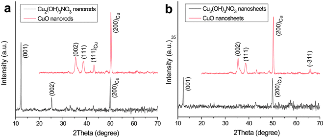 | ||
| Fig. 1 XRD patterns of Cu2(OH3)NO3 and CuO nanostructures. The peaks from the Cu substrate are indicated. | ||
Field-emission scanning electron microscopy (FESEM) images of Cu2(OH)3NO3 film synthesized in 2-proponal are shown in Fig. 2a and Fig. 2b. It can be observed that the compact film on the Cu substrate is composed of arrays of uniform nanorods with 50–100 nm in diameter and several micrometers in length. Transmission electron microscope (TEM) characterization reveals that Cu2(OH)3NO3 nanorods grow in bundles and are well-defined in shape, as shown in Fig. 2c and Fig. 2d. Selected-area electron diffraction (SAED) analysis indicates that the nanorods are single-crystalline in nature with a long axis direction perpendicular to the (010) planes, i.e., the growth direction is [010]. However, HRTEM images of the nanorods could hardly be taken due to fast structural degradation under strong electron beam irradiation. When the reaction is conducted in ethanol, arrays of uniform Cu2(OH)3NO3 nanosheets instead of nanorods are synthesized on the Cu substrate, as shown in Fig. 3a and Fig. 3b. TEM/SAED examination (Fig.3c and 3d) indicates that Cu2(OH)3NO3 nanosheets are also single-crystalline and have a rectangle shape with (001) planes as stable facets. These nanosheets have an average width and thickness of 1–2 µm and ∼20 nm, respectively.
![(a, b) FESEM images of Cu2(OH)3NO3 nanorods; (c) TEM image of a bundle of nanorods; (d) a nanorod with the growth direction along the [010] direction, of which the corresponding SAED pattern is shown in (e).](/image/article/2011/NR/c0nr00827c/c0nr00827c-f2.gif) | ||
| Fig. 2 (a, b) FESEM images of Cu2(OH)3NO3 nanorods; (c) TEM image of a bundle of nanorods; (d) a nanorod with the growth direction along the [010] direction, of which the corresponding SAED pattern is shown in (e). | ||
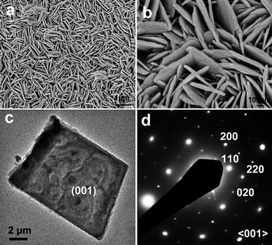 | ||
| Fig. 3 (a, b) FESEM images of Cu2(OH3)NO3 nanosheets; (c) TEM image of a single nanosheet, of which the corresponding SAED pattern is shown in (d). | ||
The above results demonstrate that the morphology of Cu2(OH)3NO3 nanostructures can be readily controlled by using different solvents, in which precursor supersaturation for nucleation and crystal growth is determined by solvent polarity and solubility. The precise control of precursor concentration and supersaturation plays a prime role in the synthesis of Cu2(OH)3NO3 nanostructures and the degree of supersaturation directly determines the crystal growth mode.23 For instance, anisotropic 1D growth might be preferable at low supersatuation, while a high degree of supersaturation in ethanol with larger polarity and solubility will favor 2D growth in view of the intrinsic layered structure of Cu2(OH)3NO3. If a solvent with high polarity such as methanol is used, bulk aggregations are produced under similar conditions as a result of the very high precursor concentration in the solution (data not shown). In general, both the concentration and supersaturation of the precursor for the formation of low-dimensional Cu2(OH)3NO3 nanostructures must be kept at a relatively low level to avoid overwhelming isotropic growth or even homogeneous nucleation in the solution.23
It has been known that layered hydroxy salts with a general composition of Mx(OH)yAz (A = NO3− or Cl−, etc.) can be used as morphology-controlled precursors for the fabrication of low-dimensional nanostructures. For example, Cu(OH)2 nanorods and Mg(OH)2 nanotubes have been synthesized from Cu2(OH)3NO3 and the Mg10(OH)18Cl2·5H2O in solution, respectively.22,24 More recently, arrays of Co3O4 nanobelts are also prepared with Co(CO3)0.5(OH)·0.11H2O as the precursor.25 In this work, arrays of CuO nanorods and nanosheets can be fabricated by in-situ conversion of Cu2(OH)3NO3 nanostructures on a Cu substrate via controlled annealing at 210 °C. The reaction can be described as follows:
| Cu2(OH)3NO3(s) → 2CuO(s) + HNO3(g) + H2O(g) |
FESEM characterization shows that after heat treatment, CuO products inherit well the nanorod or nanosheet morphology from their precursors without aggregation and collapse. This can be seen in Fig. 4. TEM examination indicates that both CuO products are polycrystalline with a grain size of less than 10 nm, possibly due to the low decomposition temperature employed.
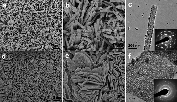 | ||
| Fig. 4 (a, b) FESEM images of CuO nanorods; (c) TEM image of a single CuO nanorod, of which the SAED pattern is shown in the inset; (d, e) FESEM images of CuO nanosheets; (f) TEM image of a single CuO nanosheet, of which the SAED pattern is also shown in the inset. | ||
For the formation of the array of Cu2(OH)3NO3 nanostructures, crystal nuclei should be generated first to induce anisotropic crystal growth on the substrate. The presence of crystal nuclei offers contact points between Cu2(OH)3NO3 nanostructures and the Cu substrate through chemical bonding. After annealing, such contacts would be much stronger because of the improved crystallinity of CuO nanostructures. The good contact between CuO nanostructures and the Cu substrate makes it possible to be directly used as integrated electrodes for LIBs without the conventional film formation process. When evaluated as anode materials for LIBs, these integrated CuO nanorod electrodes indeed exhibit high capacities with excellent cycling stability. Fig. 5a shows representative discharge/charge voltage profiles of CuO nanorod electrodes at a 0.5 C rate (1C = 670 mA g−1). The constant slopes with multiple small plateaus indicate that multi-phase transition takes place upon the conversion reaction between CuO and lithium. The initial discharge and charge capacities are found to be 1500 and 580 mAh g−1, respectively. The irreversible capacity loss of 60% in the first cycle may be mainly ascribed to diverse irreversible processes such as interfacial lithium storage, inevitable formation of solid electrolyte interface (SEI layer) and organic conductive polymer, as well as the electrolyte decomposition, which are common for most anode materials.6,26–29 Remarkably, from the second cycle onwards, CuO nanorods exhibit no capacity decay and retain a high capacity of 650 mAh g−1 even after 100 cycles, as shown in Fig. 5b. Even cycled at high rates of 1 C and 2 C, they still deliver stable capacities with comparable values of 590 and 450 mAh g−1 after 100 cycles, respectively. Considering that no ancillary materials such as polymer binder and carbon black are used in the present work, the reversible capacity and cycling ability presented above for CuO nanorod arrays are highly encouraging and are superior to most of reported CuO anodes.6,9,16,17,30–37 In comparison, the Cu2(OH)3NO3 precursor is completely electrochemically inactive despite its layered structure. Fig. 5c shows cyclic voltammograms of the CuO nanorod electrode at a scan rate of 0.1 mV s−1. In the first discharge process, two reduction peaks in the potential range of 0.1–3 V are observed at 0.9 V and 0.7 V. These reduction peaks correspond to a multi-step electrochemical reaction which involves (i) the creation of a CuII1-xCuIxO1-x/2 solid solution with CuO phase, (ii) the formation of Cu2O phase, and (iii) the decomposition of Cu2O into Cu and Li2O,1 which is consistent with discharge/charge curves with a multiple-plateau feature. During the subsequent charging process, only one anodic peak is found at 2.5 V due to the restoration of the CuO phase. The subsequent CV curves show very good reproducibility, suggesting a high degree of reversibility for the redox reaction.
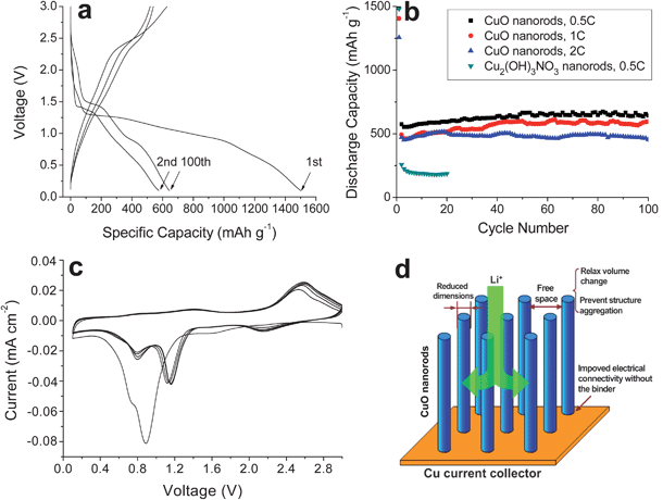 | ||
| Fig. 5 (a) Discharge/charge curves of CuO nanorods between 0.1–3.0 V at 0.5 C; (b) cycling performance of CuO nanorods at 0.5–2 C; (c) cyclic voltammograms of CuO nanorods at a scan rate of 0.1 mV s−1 between 0.1–3.0 V; (d) schematic illustration of the role of the nanorods played in the improvement of the electrochemical performance of the CuO anode. | ||
Apparently, the formation of dense arrays of nanostructures is crucial to the improved electrochemical performance of integrated CuO electrodes. The loose texture and sufficient space between the nanorods allow fast lithium ion flux across the interface and better accommodate the volume change induced by lithium insertion/extraction, as well as preventing the nanostructures from agglomeration. At the same time, the extremely reduced dimensions of CuO nanorods may also not only contribute to the improved electrode stability because of the reduced lattice strain associated with lithium intercalation, but would also increase the efficiency for charge transport because of the short diffusion length.38 On the other hand, CuO nanorods, typically several micrometers in length, need only a few contact points with the current collector to ensure electron transport, whereas the nanoparticle counterparts may easily become electrically isolated as they expand and contract during battery reactions.39 This feature may also favor the improvement of the cycling stability of the present CuO electrodes. A structural illustration for these electrodes is given in Fig. 5d to help understand the role played by proper nanostructures. With CuO nanosheets as the electrodes, the above speculation is further proved reasonable in terms of significantly improved cycling stability over 100 cycles at 0.5–1C with a capacity of 450 mAh g−1, as shown in Fig. 6. The preferable electrochemical performance of 1D nanorods than that of 2D nanosheets may be related to their lower dimensionality that not only allows much faster lithium ion and electron transport, but also better buffers the lattice stress associated to battery reactions. Lastly, it should be pointed out that it is very challenging to calculate accurately the specific capacity due to the uncertainty associated with the weighing of active materials on the substrate.
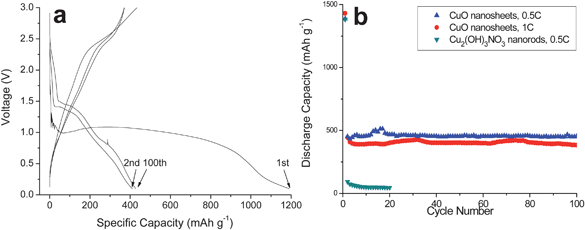 | ||
| Fig. 6 (a) Discharge/charge curves of CuO nanosheets between 0.1–3.0 V at 0.5 C; (b) cycling performance of CuO nanosheets at 0.5–1 C. | ||
Conclusions
In summary, single crystalline Cu2(OH)3NO3 nanostructures, including nanorods and nanosheets, have been controllably deposited on the Cu substrate by a facile solvothermal approach at a low temperature. With them as the morphology-controlled precursors, polycrystalline CuO nanorods and nanosheets have been obtained after simple annealing. The good contact between CuO nanostructures and the conductive Cu substrate enables their use as integrated electrodes for lithium-ion batteries without adding other ancillary materials such as carbon black or a polymer binder. As a result of the desirable electrode nano-architecture, these integrated CuO electrodes can deliver high capacities of 450–650 mAh g−1 at 0.5–2 C with excellent capacity retention over 100 cycles. This result is superior to most reported CuO anodes. The present work serves as another example to demonstrate that combining the nanostructure concept and metal oxide-based anodes could be an effective way to develop a new class of high-performance anodes for high-energy lithium-ion batteries.Acknowledgements
We gratefully acknowledge financial support from the Ministry of Education (Singapore) through the AcRF Tier-1 grant (RG 63/08, M52120096), and the National Research Foundation (Singapore) through the Clean Energy Research Program (NRF2009EWT-CERP001-036).References
- A. Débart, L. Dupont, P. Poizot, J. B. Leriche and J. M. Tarascon, J. Electrochem. Soc., 2001, 148, A1266 CrossRef CAS.
- J. H. Ku, Y. S. Jung, K. T. Lee, C. H. Kim and S. M. Oh, J. Electrochem. Soc., 2009, 156, A688 CrossRef CAS.
- P. Poizot, S. Laruelle, S. Grugeon, L. Dupont and J. M. Tarascon, Nature, 2000, 407, 496 CrossRef CAS.
- M. Wagemaker, W. J. H. Borghols and F. M. Mulder, J. Am. Chem. Soc., 2007, 129, 4323 CrossRef.
- P. Poizot, S. Laruelle, S. Grugeon and J. M. Tarascon, J. Electrochem. Soc., 2002, 149, A1212 CrossRef CAS.
- S. Y. Gao, S. X. Yang, J. Shu, S. X. Zhang, Z. D. Li and K. Jiang, J. Phys. Chem. C, 2008, 112, 19324 CrossRef CAS.
- M. H. Cao, C. W. Hu, Y. H. Wang, Y. H. Guo, C. X. Guo and E. Wang, Chem. Commun., 2003, 1884 RSC.
- L. B. Chen, N. Lu, C. M. Xu, H. C. Yu and T. H. Wang, Electrochim. Acta, 2009, 54, 4198 CrossRef CAS.
- X. P. Gao, J. L. Bao, G. L. Pan, H. Y. Zhu, P. X. Huang, F. Wu and D. Y. Song, J. Phys. Chem. B, 2004, 108, 5547 CrossRef CAS.
- S. Grugeon, S. Laruelle, R. Herrera-Urbina, L. Dupont, P. Poizot and J. M. Tarascona, J. Electrochem. Soc., 2001, 148, A285 CrossRef CAS.
- X. C. Jiang, T. Herricks and Y. N. Xia, Nano Lett., 2002, 2, 1333 CrossRef CAS.
- B. Liu and H. C. Zeng, J. Am. Chem. Soc., 2004, 126, 8124 CrossRef CAS.
- Q. M. Pan, H. Z. Jin, H. B. Wang and G. P. Yin, Electrochim. Acta, 2007, 53, 951 CrossRef CAS.
- J. C. Park, J. Kim, H. Kwon and H. Song, Adv. Mater., 2009, 21, 803 CrossRef CAS.
- X. G. Wen, W. X. Zhang and S. H. Yang, Langmuir, 2003, 19, 5898 CrossRef CAS.
- J. Y. Xiang, J. P. Tu, L. Zhang, Y. Zhou, X. L. Wang and S. J. Shi, J. Power Sources, 2010, 195, 313 CrossRef CAS.
- J. Y. Xiang, J. P. Tu, Y. F. Yuan, X. L. Wang, X. H. Huang and Z. Y. Zeng, Electrochim. Acta, 2009, 54, 1160 CrossRef CAS.
- J. T. Zhang, J. F. Liu, Q. Peng, X. Wang and Y. D. Li, Chem. Mater., 2006, 18, 867 CrossRef CAS.
- C. Massobrio, P. Rabu, M. Drillon and C. Rovira, J. Phys. Chem. B, 1999, 103, 9387 CrossRef CAS.
- D. C. Pereira, D. L. A.d. Faria and V. R. L. Constantino, J. Braz. Chem. Soc, 2006, 17, 1651 CAS.
- H. Tanaka and S. Terada, J. Thermal Anal., 1993, 29, 1011.
- S. H. Park and H. J. Kim, J. Am. Chem. Soc., 2004, 126, 14368 CrossRef CAS.
- Y. N. Xia, P. D. Yang, S. X. Sun, Y. Y. Wu, B. Mayers, B. Gates, Y. D. Yin, F. Kim and Y. Q. Yan, Adv. Mater., 2003, 15, 353 CrossRef CAS.
- W. L. Fan, S. X. Sun, L. P. You, G. X. Cao, X. Y. Song, W. M. Zhang and H. Y. Yu, J. Mater. Chem., 2003, 13, 3062 RSC.
- Y. Wang, H. Xia, L. Lu and J. Y. Lin, ACS Nano, 2010, 4, 1425 CrossRef CAS.
- J. Maier, Nat. Mater., 2005, 4, 805 CrossRef.
- X. W. Lou, C. M. Li and L. A. Archer, Adv. Mater., 2009, 21, 2536 CrossRef CAS.
- X. W. Lou, D. Deng, J. Y. Lee, J. Feng and L. A. Archer, Adv. Mater., 2008, 20, 258 CrossRef CAS.
- S. Laruelle, S. Grugeon, P. Poizot, M. Dolle, L. Dupont and J. M. Tarascon, J. Electrochem. Soc., 2002, 149, A627 CrossRef CAS.
- S. F. Zheng, J. S. Hu, L. S. Zhong, W. G. Song, L. J. Wan and Y. G. Guo, Chem. Mater., 2008, 20, 3617 CrossRef CAS.
- J. Y. Xiang, J. P. Tu, L. Zhang, Y. Zhou, X. L. Wang and S. J. Shi, Electrochim. Acta, 2010, 55, 1820 CrossRef CAS.
- Y. Y. Hu, X. T. Huang, K. Wang, J. P. Liu, J. Jiang, R. M. Ding, X. X. Ji and X. Li, J. Solid. State Chem., 2010, 183, 662 CrossRef CAS.
- H. B. Wang, Q. M. Pan, H. W. Zhao, G. P. Yin and P. J. Zuo, J. Power Sources, 2007, 167, 206 CrossRef CAS.
- E. A. Souza, R. Landers, L. P. Cardoso, T. G. S. Cruz, M. H. Tabacniks and A. Gorenstein, J. Power Source., 2006, 155, 358 CAS.
- J. Y. Xiang, J. P. Tu, X. H. Huang and Y. Z. Yang, J. Solid State Electrochem., 2008, 12, 941 CrossRef CAS.
- Q. M. Pan, M. Wang and Z. J. Wang, Electrochem. Solid-State Lett., 2009, 12, A50 CrossRef CAS.
- J. Moralesa, L. Sáncheza, F. Martínb, J. R. Ramos-Barradob and M. Sánchez, Electrochim. Acta, 2004, 49, 4589 CrossRef CAS.
- H. J. Fan, P. Werner and M. Zacharias, Small, 2006, 2, 700 CrossRef CAS.
- P. G. Bruce, B. Scrosati and J. M. Tarascon, Angew. Chem., Int. Ed., 2008, 47, 2930 CrossRef CAS.
| This journal is © The Royal Society of Chemistry 2011 |
