An algorithm for three-dimensional Monte-Carlo simulation of charge distribution at biofunctionalized surfaces
Alena
Bulyha
*a and
Clemens
Heitzinger
ab
aDepartment of Mathematics and Wolfgang Pauli Institute, University of Vienna, A–1090, Vienna, Austria. E-mail: Alena.Bulyha@univie.ac.at.; Clemens.Heitzinger@univie.ac.at.
bDepartment of Applied Mathematics and Theoretical Physics (DAMTP), University of Cambridge, Cambridge, CB3 0WA, UK. E-mail: C.Heitzinger@damtp.cam.ac.uk
First published on 8th February 2011
Abstract
In this work, a Monte-Carlo algorithm in the constant-voltage ensemble for the calculation of 3d charge concentrations at charged surfaces functionalized with biomolecules is presented. The motivation for this work is the theoretical understanding of biofunctionalized surfaces in nanowire field-effect biosensors (BioFETs). This work provides the simulation capability for the boundary layer that is crucial in the detection mechanism of these sensors; slight changes in the charge concentration in the boundary layer upon binding of analyte molecules modulate the conductance of nanowire transducers. The simulation of biofunctionalized surfaces poses special requirements on the Monte-Carlo simulations and these are addressed by the algorithm. The constant-voltage ensemble enables us to include the right boundary conditions; the DNA strands can be rotated with respect to the surface; and several molecules can be placed in a single simulation box to achieve good statistics in the case of low ionic concentrations relevant in experiments. Simulation results are presented for the leading example of surfaces functionalized with PNA and with single- and double-stranded DNA in a sodium-chloride electrolyte. These quantitative results make it possible to quantify the screening of the biomolecule charge due to the counter-ions around the biomolecules and the electrical double layer. The resulting concentration profiles show a three-layer structure and non-trivial interactions between the electric double layer and the counter-ions. The numerical results are also important as a reference for the development of simpler screening models.
1. Introduction
The motivation for this work is to provide simulations of the electrostatics near solids that are immersed in an electrolyte and that are functionalized with biomolecules. The structures considered are, e.g., the biofunctionalized surfaces of field-effect biosensors and biological membranes with proteins. The free ions in the electrolyte are influenced by the surface charge of the solid and the partial charges of the biomolecules, i.e., the ions form an electric double layer at the surface and they can act as counter-ions around the molecules. The double layer and the counter-ions interact with one another.The electrostatics of these boundary layers are crucial for the understanding of nanowire field-effect biosensors. Recent experiments have shown the possibility of detecting biomolecules by the effect of their intrinsic charge on the conductance of a semiconducting nanowire transducer.1–4 The surface is functionalized with PNA strands, DNA strands, or antibodies. When the complementary DNA strands or matching antigens bind to the surface receptors, the charge distribution at the surface changes which modulates the electrostatic potential in the semiconductor and thus its conductance. The main advantage of these biosensors is direct, label-free operation.
Despite the remarkable experimental progress in this field, the theoretical understanding of the field-effect sensors is still incomplete.5–9 In order to arrive at a quantitative understanding, a precise knowledge of the charge concentration in the surface layer is necessary and can only be provided by simulations.
The standard continuum model for the electrostatics of biomolecules is the mean-field Poisson equation with a Boltzmann term for the concentration of the free charges, then called the Poisson–Boltzmann equation.10–12 In the continuum model, the free charges are treated as point charges and included using Boltzmann statistics. The classical Poisson–Boltzmann theory is successful to study the planar electric double layer and the electrolyte bulk. Also various modifications of the Poisson–Boltzmann approach have been developed and applied to study the electric double layer around a uniformly charged spherical colloid particle13 and around an infinitely large and uniformly charged cylinder.14
However, there are experimental results which show the effect of ion size on diffusion in alkali halides15 or at the surface16 and that cannot be explained by Poisson–Boltzmann theory. Also recent simulations17–19 show that both the electrostatic and hard-sphere collisions are sensitive to ion size. To include the finite-size effects of small ions, various methods have been developed. These include canonical and grand-canonical Monte-Carlo (MC) simulations20–23 and density-functional theory.18–24 The advantages and disadvantages of these methods for mixed-sized counter-ion systems are discussed in the literature.18,24–26MC simulations agree better with experimental data since the finite size of the ions is taken into account. Although electrical double layers have been extensively studied near planar, uniformly charged surfaces23,27,28 and around isolated, infinitely large and uniformly charged cylinders,26,29,30 the ionic concentrations near groups of charged objects with various geometries and sizes at surfaces have been investigated much less.
Since field-effect sensors are extremely sensitive to screening effects and large voltages are applied across the devices in experiments, correct boundary conditions must be used in self-consistent simulations. Furthermore, in experiments very low ionic concentrations are used. To arrive at good statistics in MC simulations, this implies that a large simulation domain must be used. Since the distance between biomolecules is also small in experiments,31 this requires the capability to include several molecules in a single simulation domain (see Fig. 1). Additionally, since the electrolyte is usually buffered, it is essential to consider not only mixed-size, but also mixed-valence ionic systems. Therefore the valence of the ions can be specified as an input parameter in the MC algorithm. Finally, to calculate the electrostatic free energy of various orientations of the biomolecules,12,32–34 the PNA and DNA strands can be rotated in the MC algorithm.
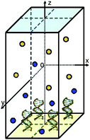 | ||
| Fig. 1 The simulation domain. Here it contains 2 × 2 molecules. | ||
These requirements were taken into account in the development of the MC algorithm and hence this work solves the problem of simulating the electrostatics of biofunctionalized surfaces at the microscopic scale for sensor applications. Here the microscopic length scale is the length scale of single molecules at the surface and it is typically in the range of a few nanometres to a few dozen nanometres. The macroscopic length scale is the length scale of a cell or of a whole sensor and it is larger by several orders of magnitude. The multiscale problem of considering both length scales at the same time was solved previously.35 By homogenization, the original Poisson equation with a fast varying charge concentration was replaced by a homogenized problem consisting of the Poisson equation with two interface conditions at the surface. The values determining the interface conditions are easily evaluated from the MC simulation results presented here. This homogenization result in conjunction with a charge-transport model makes it possible to calculate the electric current through field-effect sensors once the charge concentration in the boundary layer has been calculated. Both models together, the microscopic and macroscopic, provide self-consistent simulations of field-effect biosensors.
The rest of this paper is organized as follows. In Section 2, the MC algorithm and all the interaction potentials between the various charge carriers are described in detail. In Section 3, results from the calculation of the charge concentrations at silica surfaces functionalized with peptide nucleic acid (PNA), single-stranded deoxyribonucleic acid (ssDNA), or double-stranded deoxyribonucleic acid (dsDNA) are presented and discussed. Finally, Section 4 concludes the paper.
2. The Monte-Carlo algorithm
First, we summarize the extension of the Metropolis MC algorithm23 to the constant-voltage ensemble.28 We treat the constant-voltage ensemble as an extension of the grand-canonical ensemble, i.e., the voltage applied at the electrodes is a controlled parameter. Another parameter that has to be kept constant during the simulation is the bulk ionic concentration. This is achieved using the chemical potential energy that has to be calibrated by the iterative algorithm described below. Based on this discussion, the extensions to include molecules and the various interaction potentials between the charge carriers are then explained in detail.2.1 The simulation domain
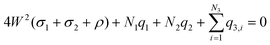
The simulation domain (see Fig. 1) consists of a finite box [−W,W] × [−W,W] × [−H,H] with H ≥ 2W that is bounded in the z-coordinate by two sheets. The interior of the box contains an electrolyte solution and one or more immobile (macro-)molecules arranged in a Cartesian grid. The x- and y-directions are parallel to the sheets and periodic boundary conditions are used in these directions. The box has hard, impenetrable walls at z = −H and z = H carrying uniform surface charges with densities ρ and 0, respectively. Two additional charge densities σ1 and σ2 are associated with the sheets and are adjusted to the desired potential difference. If there is only one molecule, it is linked at the center of the lower wall at (0, 0, −H). If the box contains more molecules, they are arranged in an equidistant grid and each molecule is centered in its grid cell.The box confines N1 cations with charge q1, N2 anions with charge q2, and N3 partial charges of the molecules with charges q3, i (e.g., the phosphate groups of the DNA backbone). It is required that the whole system is electrically neutral, i.e., that the equation
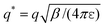
All types of ions are modeled as charged hard spheres with a diameter of 0.3 nm and water is considered as a continuous structure-less medium with a constant relative permittivity of εr = 80. To speed up electrostatics calculations, it is furthermore assumed that εr = 80 everywhere in the simulation box. The minimal separation between ions and the boundaries is l = 0.1 nm. The temperature of the system is T = 300 K.
In this work the PNA, single-stranded DNA, and double-stranded DNA oligomers are modeled as impenetrable cylinders with two hemispheres at the top and at the bottom. The oligomers consist of a certain number of base pairs that determines their height (each base pair has a height of 0.34 nm) and they have a radius of 1 nm. They are bound orthogonal to the surface so that a hemisphere touches the surface. The PNA oligomers are uncharged in the model, whereas the ssDNA and dsDNA oligomers carry point charges of one electron charge at the location of each phosphate group of their backbones. Thus the partial charges are distributed along a helix or a double helix in the right rotational direction with a distance from the cylinder surface equal to the oxygen atom radius of 60 pm.
2.2 Metropolis Monte-Carlo simulation in the constant-voltage ensemble
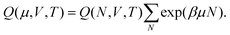
The simulation samples the configuration space by randomly changing the placement of ions in the simulation box while avoiding overlaps22,36 and by transferring a random amount of charge between the sheets.28In the sequel we use the notations of ref. 20. In the canonical ensemble (i.e., N, V, T are constant), we denote the partition function for a system of N particles from the same species (the anions or the cations) in a volume V at temperature T by QN and we denote the total energy of the system in state N by EN. The partition function QN can be factorized into a product of kinetic (ideal gas) and potential (excess) parts,
 | (1) |
 . The excess part in the canonical ensemble is
| QexN = V−N∫exp(−βEN(r))dr. |
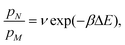
We denote the difference in electrostatic potential energy between two configurations by Utot and the chemical potential energy by μ. (To simplify notation we write Utot instead of ΔUtot in the following.) As usual T denotes the temperature, kB the Boltzmann constant, and β = 1/(kBT). The probability that the system occupies state N is pN = QN−1exp(−βEN) and therefore the ratio of the probabilities of the old state N and the new state M can be written as
(1) translation of an ion with probability
| P = min(1,exp(−βUtot)), |
(2) insertion of an ion with probability
| P = min(1,ν exp(−βUtot + βμ)), |
(3) deletion of an ion with probability
| P = min(1,ν exp(−βUtot − βμ)), and |
(4) charge transfer between the two sheets with probability
P = min(1,exp(−βUtot + βAΦ![[small sigma, Greek, circumflex]](https://www.rsc.org/images/entities/i_char_e111.gif) )). )). |
In case (1), the translation of an ion, the temperature T, the number of the ions (N = M) and the volume of the system V are constant. Therefore, QigNQexN = QigMQexM = Q(N,V,T) and hence ν = 1. Furthermore the total energy of the system in a certain state is equal to the electrostatic potential in this state, i.e., ΔE = Utot.
In cases (2) and (3) ions are exchanged with the surrounding, but the chemical potential μ, the temperature T, and the volume V remain constant and we have
Hence for the insertion of an ion we have ΔE = ΔUtot − μ and ν = QigN+1/QigN = V/(N + 1)Λ3. Case (3), the deletion of an ion, is symmetrical to the insertion and we obtain ν = (NΛ3)/V and ΔE = ΔUtot + μ.
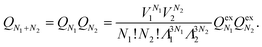
In order to retain the charge neutrality of the simulation box, insertion and deletion of ions are always performed pairwise, i.e., both an anion and a cation are inserted or deleted in one step. We therefore rewrite the partition function QN from (1) for two types of particles, namely anions and cations, as
This yields μ = ∑iμi and ν = Πiνi, where the sum is over all ion species i.
In case (4), the charge transfers between sheets, the voltage difference Φ between the sheets remains constant additionally. The partition function can be written as an integral over the possible charge densities σ of the sheet,
| Q(N,V,T,Φ) = ∫σQ(N,V,T)exp(βAΦσ)dσ, |
, where the charge density is transferred between the two sheets (see also Section 2.4). The equation σ1 = −σ2 always holds for the charge densities of the sheets. Since the whole system is neutral, the number of ions is chosen so that the charge of the molecules and the surface charge ρ are compensated.
2.3 The chemical potential
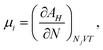
The chemical potential μi of the ith species is defined as the change in the Helmholtz free energy upon insertion of a test particle, i.e.,where the index means that the volume V, the temperature T, and the other particle numbers Nj (j ≠ i) are constant. The Helmholtz free energy of the canonical ensemble is given by
and hence the chemical potential is
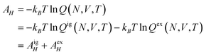
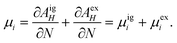
Therefore the excess chemical potential is the difference between the chemical potential of a given species and that of an ideal gas under the same conditions. The chemical potential of an ideal gas is given by
| μi = kBTln ρi + μexi. | (2) |
The excess chemical potential μexi can be calculated iteratively21 as follows. After starting with an estimated value like μexi = −1 or μexi = 0, in each iteration step n the value of μexi, n is calculated by
| μexi, n = μi, n − 1 − kBTln〈ρ〉n, | (3) |
Combining the probabilities of insertion or deletion of an ion (see Section 2.2) and the identity Λ3 = exp(lnΛ3) with eqn (2) and (3) we find that the probabilities do not depend on the thermal de-Broglie wavelength, i.e., Λ = 1.
2.4 Calculation of the electrostatic potential energy
The total potential energy Utot of the system can be divided into several terms due to the superposition principle and hence we can consider the interaction between each pair of charge types and calculate the corresponding potential energies separately. In the following, the indices I, S, and P denote ions, sheets, and partial charges of the molecules, respectively.The movements of charges, resulting in changes in the potential energy terms, can be divided into three groups:
1. Utot = UIS + UII + UIP by translation, insertion, or deletion of ions,
2. Utot = USS + USI + USP by charge transfer between the two sheets, and
3. Utot = UPS + UPI + UPP by movements and deformations of the molecule.
In the following we describe the calculations of the potential energy that are required for the probability calculation in the MC loop. The variables and their units or values are summarized in Table 1.
| Meaning | Variable | Unit or value |
|---|---|---|
| Vacuum permittivity | ε 0 | 8.8541878 × 10⁻³ C V−1 nm−1 |
| Elementary charge | q | 1.6021917 × 10⁻¹⁹ C |
| Boltzmann constant | k B | 1.3806 × 10⁻²³ C V K−1 |
| β | 2.4144 × 10²⁰ C−1 V−1 | |
| Thermal de-Broglie wavelength | Λ | nm |
| Number of particles | N | 1 |
| Temperature | T | K |
| Ionic concentration | c | M |
| Surface charge density |
ρ,σ, |
C nm−2 |
| Charge | q i | C |
| Valence | z | 1 |
| Electrostatic potential energy | U | J |
| Helmholtz free energy | A H | J |
| Voltage | Φ | V |
| Chemical potential | μ | J |
| Length | W,H,L,d,h,r | nm |
| Area | A | nm2 |
| Volume | V | nm3 |
 | (4) |
 , zi* = q*zi, and σ* = q*σ/q. Hence the calculation for the ith ion is simply
| βUIS, i = −2πzi*σ*r, |
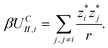
The term UIIC is the Coulomb charge–charge interaction

Analogously to the method described in ref. 23 and 27, the interaction between the test particle i and a charged plane of size L × L carrying a uniform charge density of qj/L2 is written as
| UIIout(i,j) = UII∞(i,j) − UIIin(i,j), |
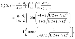 | (5) |
 is transferred between the two sheets. We denote the distance between the sheets by d, the area of the sheets by A, and the charge density of the sheet at z = −H by σ1 and the density of the one at z = H by σ2. The charge transfer between the two sheets can be described as an axially parallel transport of charge q′ from an infinitesimal segment of one sheet to the corresponding segment of the second sheet.
The term USS describes the interaction between the sheet of area A and the infinite sheet. Using eqn (4) with r = d and qi = q′ and integrating, we obtain
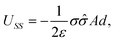 | (6) |
 . This yields
| βUSS = −2πσ**Ad. |
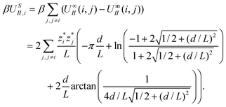
and the corresponding increase of charge density at the second sheet. In the constant-voltage ensemble, the terms USI and USP describe the interactions between a sheet, whose charge density is changed, and a point charge qj (the charge of an ion or a partial charge of a molecule). Analogously to the calculations for the term UII, we have to take into account the long-range contributions from the rest of the boxes.
Again we split this term into the sheet–charge interaction UqSI and the interaction between the sheet (of area A) and the outside charged plane corresponding to the point charge qj, i.e.,
| USI(j) = UqSI(j) + (U∞SI(j) − UinSI(j)). |
Using eqn (5) with qi = A, where A = L2, we find
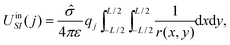
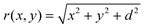 and d is the distance between the sheet and the point charge.
The potential energy dUqSI of qj due to an infinitesimal segment dxdy of the sheet with charge q′ = dxdy can be written as
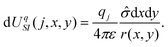
By integrating over all infinitesimal segments we find UqSI(j) = UinSI(j).
The interaction U∞SI(j) between the sheet of area A and the infinite sheet corresponding to the point charge qj is found from eqn (6) using a charge density of σ = qj/L2 for the infinite sheet. We have
3. Simulation results and discussion
We investigate surfaces functionalized with different types of biomolecules, different surface charges, and different applied voltages. In order to calculate the charge densities and the amount of screening, we consider four different situations. In the first situation, no molecules are present and an electric double layer is formed. This situation provides the baseline for the next simulations and a check of our simulations with the large body of work on electric double layers. In the second situation, an uncharged cylindrical molecule, i.e., PNA, is present. In a sensor setting this means that the surface has been functionalized, but no target molecules are present. In the third situation, a charged cylindrical molecule, i.e., single-stranded DNA, is present. This situation means that a strand of ssDNA has bound to the PNA from the first situation and is being detected by the redistribution of charges. It can also mean that the surface was functionalized with ssDNA and no target molecule is present yet. In the fourth situation, a charged cylindrical molecule with twice the amount of charge, i.e., double-stranded DNA, is present. This situation means that the probe strand from the third situation is now bound to a complementary target strand.In field-effect biosensors, the difference in the charge distribution between the second and third situations and between the third and fourth situations is crucial for the functioning of these sensors and provides the detection mechanism.
In the simulations the sheet that corresponds to the sensor surface is located at z = −50 nm and the oligomers have z-coordinates in the interval [−50,−44.6] nm. The simulations are three-dimensional and the concentration profiles are shown as functions of the z-coordinate. In general, the simulation domain is not symmetrical around z = 0.
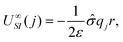
The simulation box can contain several molecules arranged in a grid. Hence we first investigate the influence of the number of molecules in a box on the resulting concentration profiles all else being equal. Fig. 2 shows concentration profiles for boxes containing 2 × 2, 3 × 3, 4 × 4, and 5 × 5 oligomers under the same conditions. The small differences in the concentration profiles are due to the slightly different approximations made during the calculation of interactions between a point charge and a sheet outside of the box (see Section 2.4). In the following simulations, we use boxes containing 3 × 3 oligomers and 100 nm high, since for this size there are always enough ions present to ensure good statistics in the MC loop.
 | ||
Fig. 2 Density profiles for a 1![[thin space (1/6-em)]](https://www.rsc.org/images/entities/char_2009.gif) :1 electrolyte and boxes containing different numbers of dsDNA strands. Here and in the following figures c is the concentration of the electrolyte, ρ is the surface charge density of the sheet at −50 nm, and V is the applied electrostatic potential between the two sheets. :1 electrolyte and boxes containing different numbers of dsDNA strands. Here and in the following figures c is the concentration of the electrolyte, ρ is the surface charge density of the sheet at −50 nm, and V is the applied electrostatic potential between the two sheets. | ||
The nominal simulation parameters for the following simulations are shown in Table 2. In the following, the normalized surface charge density denoted by ρ is given in units of elementary charges per square nanometre.
| Salt concentration | 0.01 M |
| Potential difference | 0 mV |
| Surface charge density | 0 q nm−2 |
| Macromolecule separation | 8 nm |
| Number of macromolecules | 3 × 3 |
Concentration profiles for four different molecule types are shown in Fig. 3: no molecules, PNA, ssDNA, or dsDNA are present. The small influence of the steric effect of the uncharged PNA compared to no molecules is seen. The simulations with charged molecules show that the ionic concentration in the intermolecular space differs substantially from the bulk concentration. There is also a substantial change in charge distribution after hybridization of a second strand. Moreover the maximum value of cation concentration and the minimum value of anion concentration are reached at the middle of the molecules.
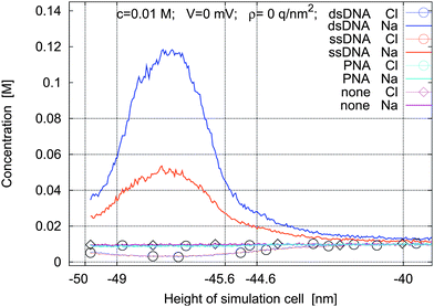 | ||
| Fig. 3 Concentration profiles for a 1:1 electrolyte for four types of macromolecules under nominal simulation parameters. | ||
The concentration of the molecules can be varied by varying the grid spacing. In Fig. 4, the concentration profiles for ssDNA and dsDNA and three grid spacings of 5 nm, 8 nm, and 11 nm are shown. The increase or decrease of the distance between the molecules leads to the expected change in the ion concentration in the intermolecular space.
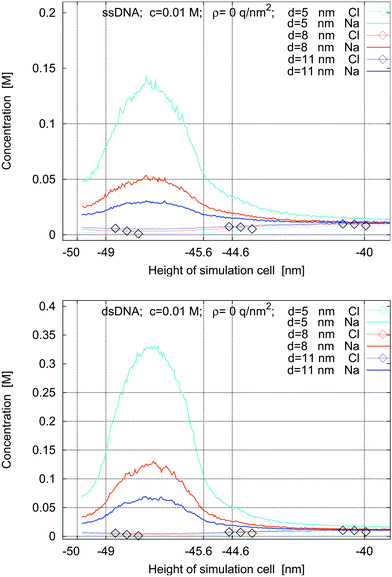 | ||
| Fig. 4 Concentration profiles for ssDNA (top) and dsDNA (bottom) for a surface charge density of ρ = 0 q nm−2, for a bulk concentration of 0.01 M, and with no applied voltage. The molecules are placed on grids with spacings of 5 nm, 8 nm, and 11 nm. | ||
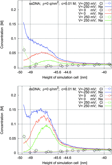
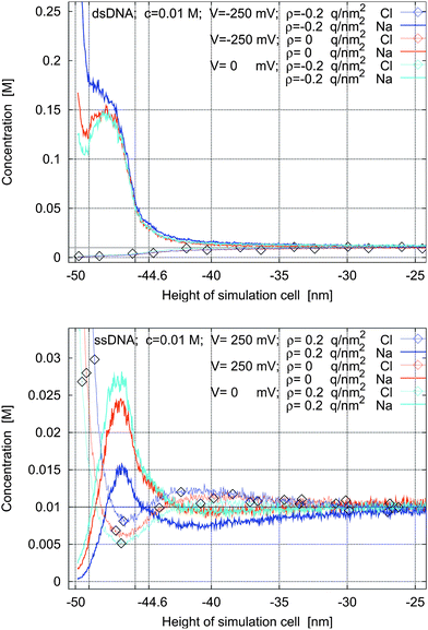
Fig. 5 and 6 show the ionic concentration profiles for different voltages applied across the box and for surface charge densities of ρ = 0 q nm−2 and ρ = −0.2 q nm−2 at the left sheet. The molecules considered are ssDNA and dsDNA.
 | ||
| Fig. 5 Concentration profiles for ssDNA and dsDNA for a surface charge density of ρ = 0 q nm−2 and for applied potentials of −250 mV, 0 mV, and 250 mV. | ||
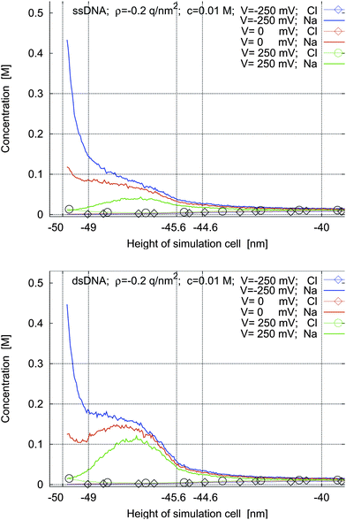 | ||
| Fig. 6 Concentration profiles for ssDNA and dsDNA for a surface charge density of ρ = −0.2 q nm−2 and for applied potentials of −250 mV, 0 mV, and 250 mV. | ||
If the left sheet is at a negative voltage (blue lines), the sodium concentration (lines without marks) at the sheet and in the intermolecular space is increased compared to the case of no applied voltage (red lines). At the same time, the chlorine concentration decreases. Fig. 6 quantifies how much this effect is more pronounced when there is an additional charge on the left sheet. The charge density of ρ = −0.2 q nm−2 is the charge density of silicon oxide in water at pH = 7. It is seen that in this case the electric double layer and the charge cloud of the counter-ions of the molecules overlap. Therefore they have to be modeled self-consistently and cannot be separated: this non-trivial behavior is clearly observed in the unmarked blue lines in Fig. 5 and the unmarked red lines in Fig. 6.
If the left sheet is at a positive voltage (green lines), the chlorine concentration (lines with circles) in the electric double layer at the sheet is much increased. At the same time, the concentration of the sodium counter-ions (lines without marks) in the intermolecular space is decreased compared to the case of no applied voltage (red lines). When there is an additional negative charge on the left sheet (Fig. 6), there is no increase of chlorine in the electric double layer. It is also worth noting that the concentration of the sodium counter-ions is increased for all applied voltages, significantly in some cases, when the surface is negatively charged compared to the uncharged case.
If there is no applied voltage, the concentration profiles for different molecules and different surface charge densities of the left sheet are similar to the concentration profiles shown in Fig. 5.
In Fig. 7, concentration profiles for no molecules and for PNA are shown. The charge density of the left sheet is varied and there is no applied potential. The formation of electric double layers at charged plates in an electrolyte is an often studied situation, although usually high electrolyte concentrations are used.17,18,25,37 The concentration profiles of cations and anions are symmetric in both cases with respect to positive and negative surface charge densities of the sheet. This verifies the MC algorithm.
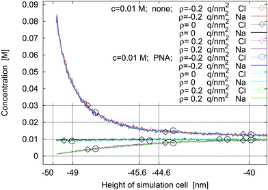 | ||
| Fig. 7 Concentration profiles for no molecules and for PNA and for surface charge densities of ρ = −0.2 q nm−2, ρ = 0, and ρ = +0.2 q nm−2 with no applied potential. | ||
In Fig. 8, we next investigate the situation where a negative charge on the left sheet and the negative charge of the molecules determine the concentration profiles of the ions (top figure). The charge of the sheets has been modified by an applied voltage as well (blue and red lines). If the net charge of the plate is negative and much smaller than the total charge of the DNA strands, the concentration profiles of the cations show two peaks located near the cathode and within the intermolecular space (red and cyan lines in the top figure in Fig. 8). Hence there are two areas with high cation concentration. As the charge of the cathode decreases, the second peak becomes wider until both areas overlap. The behavior of the anions is simpler: their concentration increases with increasing distance from the left sheet until it reaches the bulk concentration.
 | ||
| Fig. 8 Concentration profiles for ssDNA and dsDNA for various charge densities of the left sheet and for various applied potentials. | ||
If the net charge of the sheet is positive (bottom figure in Fig. 8), the behavior is more complicated and we can discern three layers. The first and third peaks correspond to maxima in the anion concentrations and the second peak corresponds to maxima in the cation concentrations. By increasing the surface charge, the second peak is shifted slightly away from the plate, the cation concentration in the intermolecular space is decreased, and the anion concentration in the third layer (near the bulk) becomes higher than the cation concentration.
Thus we observe a complicated behavior of three interacting layers: first, there is an electric double layer at the boundary; second, there is a layer caused by the molecule charges; and third, there is a boundary layer above the molecule layer and between the bulk. The third layer is effectively a double layer caused by the molecule layer.
In Fig. 9 and 10 we study the modification of the concentration profiles when the electrolyte concentration is reduced from 0.02 M to 0.01 M and then to 0.005 M. In Fig. 9 there is no charge on the left sheet, whereas in Fig. 10 the left sheet is negatively charged.
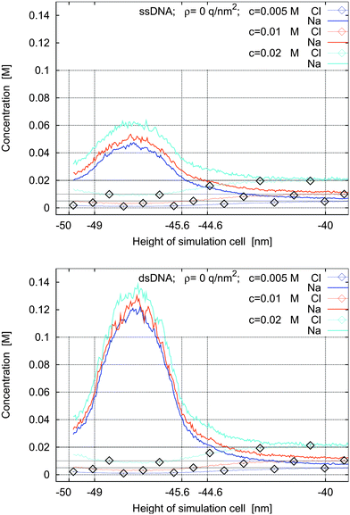 | ||
| Fig. 9 Concentration profiles for ssDNA (top) and dsDNA (bottom) for a surface charge density of ρ = 0 q nm−2 and for bulk electrolyte concentrations of 0.005 M, 0.01 M, and 0.02 M. | ||
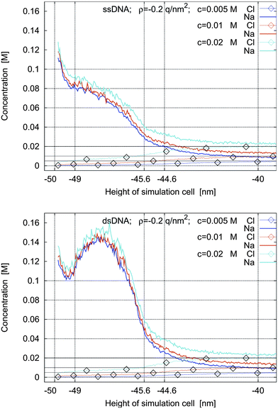 | ||
| Fig. 10 Concentrations profiles for ssDNA (top) and dsDNA (bottom) for a surface charge density of ρ = −0.2 q nm−2 and for bulk electrolyte concentrations of 0.005 M, 0.01 M, and 0.02 M. | ||
The simulations show that the concentration of the counter-ions around the molecules decreases slightly with decreasing bulk electrolyte concentration. In three of the four cases, the counter-ion concentrations show maxima in the intermolecular space and reach them approximately at the middle of the intermolecular space. In the fourth case, when the left sheet is negatively charged and ssDNA is present, the concentration profiles are monotone.
The qualitative behavior of the concentration profiles in these simulations is the same regardless of the bulk electrolyte concentration. The salt concentration is an important quantitative, but not a crucial qualitative parameter in the simulations. In practice it is chosen to fulfil experimental requirements such as DNA hybridization.
4. Conclusions
In this work, the simulation capability for ionic concentration profiles at charged surfaces functionalized with molecules was developed. The model and algorithm are general enough to consider any type of charged surface functionalized with rigid molecules. The simulations are three-dimensional and a potential difference can be applied across the simulation box. The physical systems that can be simulated are, e.g., the boundary layers of field-effect biosensors and biomolecules at membranes. The algorithm is general enough to investigate systems with low electrolyte concentrations and high surface densities of molecules without excessive simulation times.It was found that due to the presence of the charged molecules, the ionic concentration profiles generally exhibit a three-layer structure. The first layer is the electric double layer due to the charged surface, the second layer is due to counter-ions between the molecules, and the third layer is a boundary layer above the layer of the biomolecules. The interaction between the electric double layer and the counter-ions is non-trivial and necessitates this kind of quantitative investigation.
The important simulation results for engineering applications are the concentrations of screening charges (i.e., counter-ions) around different kinds of biomolecules. For example, it was found that the bulk electrolyte concentration determines the amount of counter-ions in a highly nonlinear manner. This work is an essential building block for the quantitative understanding of field-effect biosensors, since it provides the understanding of the electrostatics of the crucial boundary layer.
5. Acknowledgments
This work was supported by the FWF (Austrian Science Fund) project No. P20871-N13, by the WWTF (Viennese Science and Technology Fund) project No. MA09-028, and by the EU project DEASE (contract MEST-CT-2005-021122). This publication is based on work supported by Award No. KUK-I1-007-43, funded by the King Abdullah University of Science and Technology (KAUST).We thank Deszo Boda for providing the initial Monte-Carlo source code for flat, unfunctionalized surfaces.
The source code of the Monte-Carlo simulator is available from the authors upon request.
References
- F. Patolsky, B. P. Timko, G. Yu, Y. Fang, A. B. Greytak, G. Zheng and C. M. Lieber, Science, 2006, 313, 1100–1104 CrossRef CAS.
- E. Stern, J. F. Klemic, D. A. Routenberg, P. N. Wyrembak, D. B. Turner-Evans, A. D. Hamilton, D. A. LaVan, T. M. Fahmy and M. A. Reed, Nature, 2007, 445, 519–522 CrossRef CAS.
- E. Stern, A. Vacic, N. K. Rajan, J. M. Criscione, J. Park, B. R. Ilic, D. J. Mooney, M. A. Reed and T. M. Fahmy, Nat. Nanotechnol., 2009, 5, 138–142.
- G. Zheng, F. Patolsky, Y. Cui, W. U. Wang and C. M. Lieber, Nat. Biotechnol., 2005, 23, 1294–1301 CrossRef CAS.
- J. F. Klemic, E. Stern and M. A. Reed, Nat. Biotechnol., 2001, 19, 924–925 CrossRef CAS.
- A. Poghossian, A. Cherstvy, S. Ingebrandt, A. Offenhäuser and M. J. Schöning, Sens. Actuators, B, 2005, 111–112, 470–480 CrossRef.
- M. J. Schöning and A. Poghossian, Analyst, 2002, 127, 1137–1151 RSC.
- M. J. Schöning and A. Poghossian, Electroanalysis, 2006, 18, 1893–1900 CrossRef CAS.
- H. Hunt and A. Armani, Nanoscale, 2010, 2, 1544–1559 RSC.
- P. Debye and E. Hückel, Physikalische Zeitschrift, 1923, 24, 185–206 Search PubMed.
- K. A. Sharp and B. Honig, Annu. Rev. Biophys. Biophys. Chem., 1990, 19, 301–332 CrossRef CAS.
- A. H. Talasaz, M. Nemat-Gorgani, Y. Liu, P. Stahl, R. W. Dutton, M. Ronaghi and R. W. Davis, Proc. Natl. Acad. Sci. U. S. A., 2006, 103, 14773–14778 CrossRef CAS.
- C. W. Outhwaite and L. B. Bhuiyan, Mol. Phys., 1991, 74, 367–381 CrossRef CAS.
- M. A. Lampert and R. S. Crandall, Chem. Phys. Lett., 1980, 72, 481–486 CrossRef CAS.
- G. Ara and J. G. Mullen, Phys. Rev., 1966, 143, 663–665 CrossRef.
- A. M. Tikhonov, J. Chem. Phys., 2009, 130, 024512 CrossRef.
- M. Valiskó, D. Henderson and D. Boda, J. Phys. Chem. B, 2004, 108, 16548–16555 CrossRef CAS.
- M. Valiskó, D. Boda and G. Gillespie, J. Phys. Chem. C, 2007, 111, 15575–15585 CrossRef CAS.
- S. Ravindran and J. Wu, Condensed Matter Physics, 2005, 8, 377–388 Search PubMed.
- M. P. Allen and D. J. Tildesley, Computer Simulation of Liquids, Oxford University Press, Oxford, New York, 1987 Search PubMed.
- A. Malasics, D. Gillespie and D. Boda, J. Chem. Phys., 2008, 128, 124102 CrossRef.
- N. Metropolis and S. Ulam, J. Am. Stat. Assoc., 1949, 44, 335–341.
- G. M. Torrie and J. P. Valleau, J. Chem. Phys., 1980, 73, 5807–5816 CrossRef CAS.
- D. Boda, D. Henderson, P. Plaschko and W. R. Fawcett, Mol. Simul., 2004, 30, 137–141 CrossRef CAS.
- D. Boda, W. R. Fawcett, D. Henderson and S. Sokołowski, J. Chem. Phys., 2002, 116, 7170–7176 CrossRef CAS.
- K. Wang, Y.-X. Yu, G.-H. Gao and G.-S. Luo, J. Chem. Phys., 2005, 123, 234904 CrossRef.
- D. Boda, K.-Y. Chan and D. Henderson, J. Chem. Phys., 1998, 109, 7362–7371 CrossRef CAS.
- K. Kiyohara and K. Asaka, J. Chem. Phys., 2007, 126, 214704 CrossRef.
- K. Wang, Y.-X. Yu and G.-H. Gao, Phys. Rev. E: Stat., Nonlinear, Soft Matter Phys., 2004, 70, 011912 CrossRef.
- T. Goel, C. N. Patra, S. K. Ghosh and T. Mukherjee, J. Chem. Phys., 2010, 132, 194706 CrossRef.
- A. W. Peterson, R. J. Heaton and R. M. Georgiadis, Nucleic Acids Res., 2001, 29, 5163–5168 CrossRef CAS.
- C. Heitzinger, N. J. Mauser, C. Ringhofer, Y. Liu and R. W. Dutton, Proc. Simulation of Semiconductor Processes and Devices (SISPAD 2009), San Diego, CA, USA, 2009, pp. 86–90 Search PubMed.
- C. Heitzinger, Y. Liu, N. J. Mauser, C. Ringhofer and R. W. Dutton, J. Comput. Theor. Nanosci., 2010, 7, 2574–2580 CrossRef CAS.
- C. Heitzinger and C. Ringhofer, Commun. Math. Sci., 2011, 40 Search PubMed , in print.
- C. Heitzinger, N. Mauser and C. Ringhofer, SIAM J. Appl. Math., 2010, 70, 1634–1654 CrossRef.
- N. Metropolis, A. W. Rosenbluth, M. N. Rosenbluth, A. H. Teller and E. Teller, J. Chem. Phys., 1953, 21, 1087–1092 CrossRef CAS.
- D. Boda, D. Henderson and K.-Y. Chan, J. Chem. Phys., 1999, 110, 5346–5350 CrossRef CAS.
| This journal is © The Royal Society of Chemistry 2011 |