Mechanically interlocked gold and silver nanoparticles using metallosupramolecular catenane chemistry†
Carl A.
Otter
,
Philipus J.
Patty
,
Martin A. K.
Williams
,
Mark R.
Waterland
* and
Shane G.
Telfer
*
MacDiarmid Institute for Advanced Materials and Nanotechnology, Institute of Fundamental Sciences, Massey University, Palmerston North, New Zealand. E-mail: s.telfer@massey.ac.nz; m.waterland@massey.ac.nz
First published on 25th January 2011
Abstract
We have employed the toolbox of metallosupramolecular chemistry to mechanically interlock gold and silver nanoparticles. A specifically designed PEGthiol-functionalized bis(phenanthroline)copper(I) complex acts to ‘catenate’ the nanoparticles. The interlocked assemblies were characterised by three complementary techniques: DLS, SERS and TEM.
The controlled assembly of metal nanoparticles (NPs) into specific arrays is of significant current interest.1,2 The range of sensing devices that have been developed over the last decade exemplify the promising functional properties of well defined NP clusters.3Gold nanoparticles (AuNPs) can be aggregated4 by agents as diverse as metal ions,5 polytopic molecular thiols,6DNA,7 pseudo-rotaxanes,8 and peptide amphiphiles.9 Strategies have also emerged for the enrichment10 and separation11 of AuNP dimers and oligomers. Studies on these small assemblies have shed light on fundamental questions regarding the optical and electronic coupling of NPs1 and on intriguing problems such as the conductance of single molecules.12
In this light, NPs that are catenated by molecular hoops on their surfaces represent very appealing targets (Fig. 1a). It is envisaged that catenated NPs will combine the functional features of their NP components with those of catenanese.g., molecular machine/motor functionality.13 The mechanical interlocking of the constituent NPs provides a stable yet chemically modifiable interparticle link and positions them with a well defined separation. The size of catenated arrays can in principle range from a dimer (with a single hoop per NP) to infinite aggregates (with multiple hoops per NP).
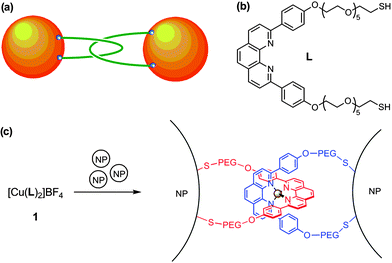 | ||
| Fig. 1 (a) A catenated NP dimer. (b) The structure of ligand L. (c) The catenation of two NPs by complex 1. | ||
These possibilities motivated us to study the assembly of catenated nanoparticles using the toolbox of metallosupramolecular chemistry (Fig. 1). The design of the nanoparticle linker (1) was informed by the pioneering work of Sauvage et al.13a,c,d The copper(I) centre in this complex arranges two phenanthroline (phen) ligands with an orthogonal disposition and two rigid phenyl substituents direct polyethylene glycol (PEG) chains away from each side of the molecule. These chains, which confer water solubility on 1, are terminated by thiol groups that can bind to two metal NPs. In doing so, complex 1 both mechanically interlocks the NPs and positions itself in an electromagnetic hotspot (Fig. 1c).14,15 In combination with resonance or pre-resonance enhancement from the intense MLCT transition associated with the Cu(I)–phen unit of 1, catenated nanoparticles are anticipated to generate extremely intense surface-enhanced Raman scattering signals.14
Another mode of nanoparticle linking by 1 can be envisioned whereby the linker is ‘twisted’ and one arm of two different ligands attaches to each NP. Although direct experimental evidence to categorically distinguish this binding mode from that presented in Fig. 1a is impossible to obtain, the twisted mode can be ruled out on the basis of the strain that this would induce (the PEG arms would be severely kinked) and the work of Sauvage et al. This group has demonstrated that the covalent tethering of the arms of related phenanthroline–PEG ligands to give [2]catenanes proceeds in high yield and to the exclusion of structures where the arms of different ligands are connected.16
Ligand L was prepared starting from 1,10-phenanthroline and reaction with [Cu(CH3CN)4]+ readily generates [CuL2]+ (1).‡ No evidence was found for any Cu–thiol interactions in solution, probably due to the strong affinity of the phenanthroline chelates for copper(I). The aggregation of citrate-coated gold nanoparticles (AuNPs) by 1 was monitored as a function of the 1![[thin space (1/6-em)]](https://www.rsc.org/images/entities/char_2009.gif) :AuNP ratio by three complementary methods: dynamic light scattering (DLS), surface-enhanced Raman scattering (SERS) and transmission electron microscopy (TEM). The concentration of the AuNPs in solution was of the order of 10−10 M.
:AuNP ratio by three complementary methods: dynamic light scattering (DLS), surface-enhanced Raman scattering (SERS) and transmission electron microscopy (TEM). The concentration of the AuNPs in solution was of the order of 10−10 M.
The size distribution of free AuNPs (in the absence of 1) was extracted from DLS data (Fig. 2a) using Contin, which provides a discrete distribution (36.0 nm).17DLS analysis using a cumulant method, which assumes a priori a Gaussian size distribution,18 is presented in the ESI†. The DLS results from the two methods agree with respect to the mean size of the scatterers, and these estimates are in accord with electronic absorption spectroscopy (λspr = 526 nm, 36 nm)19 and TEM (35.2 nm, s.d. = 11%).
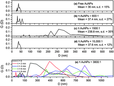 | ||
| Fig. 2 (a–d) The intensity weighted size distribution, G(D), of arrays of 36 nm citrate-coated AuNPs linked by 1 as measured by DLS. (e) Temporal evolution of the size distribution of the arrays at a 1:AuNP ratio of 3800:1. | ||
DLS data were recorded after 1 was added to separate solutions of AuNPs to give 1:AuNP ratios between 600:1 and 15000:1. At a 600:1 ratio the mean diameter of the AuNPs increases slightly and the distribution clearly tends towards larger particles (Fig. 2b). At a 1500:1 ratio there is a dramatic increase in the measured average particle size to 240 nm (Fig. 2c). Changes in the particle size distribution were monitored over time at a 3800:1 ratio (Fig. 2e). The data show a steady increase in the average particle size over a 10 minute period, resulting in aggregates of several hundred nanometres. On the other hand, a 15000:1 ratio caused only a slight increase in the mean particle size (37.6 nm), which remained constant over a 10 minute time period.
SERS spectra of these solutions were recorded following the DLS measurements. The intensities of the SERS signals are sensitive to the 1:AuNP ratio (Fig. 3): the signal intensity was greatest at the 1500:1 ratio, but significantly weaker at the 600:1 ratio and nonexistent at the 15000:1 ratio (and in the absence of 1). The SERS spectra of the 1/AuNP aggregates resemble the resonance Raman spectra of [Cu(phen)2]+ complexes,20 confirming that the signals emanate from scattering by molecules of 1 and consequently that 1 is responsible for the NP aggregation. The excellent signal-to-noise ratio of the 1500:1 sample demonstrates strong plasmon resonance enhancement from the AuNPs. As the excitation wavelength was 633 nm, resonant enhancement from the MLCT transition of 1 is also expected to contribute to the Raman signal intensity.
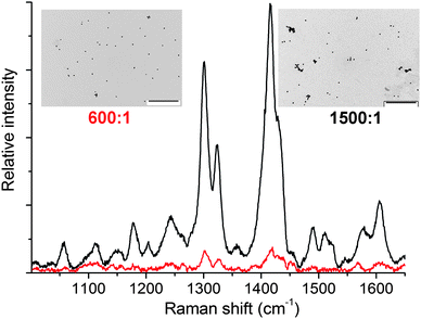 | ||
| Fig. 3
SERS spectra (λexc = 633 nm) of 36 nm citrate-coated AuNPs with AuNP:1 ratios of 600:1 (red) and 1500:1 (black). Representative TEM images are also shown as insets (scale bars = 1000 nm). | ||
Isolated AuNPs are observed by TEM (Fig. S8†) in the absence of 1 and at a 1:AuNP ratio of 15000:1. Scattered oligomers are evident at the 600:1 ratio, and extended clusters of between 2 and 20 NPs are widespread at the 1500:1 ratio (Fig. 3), with only about 20% of the NPs existing in a non-aggreagted form.
DLS, SERS and TEM represent complementary techniques for developing a comprehensive picture of the aggregation of AuNPs into mechanically interlocked arrays by 1, as summarized in Fig. 4. The DLS data suggest that some aggregation occurs at the 600:1 ratio, and the appearance of peaks in the size distribution at 43 nm and 57 nm can be tentatively assigned to NP dimers and trimers (Fig. 4a). This is consistent with a relatively weak SERS signal, as only a small number of hotspots are generated, and TEM, which detects a few small clusters. At the 1500:1 (and 3800:1) ratio the large average particle size measured by DLS, coupled with high SERS signal intensity, implies that large clusters of interlocked AuNPs are induced (Fig. 4b). However, at the 15000:1 ratio, the DLS measurement registers only a slight increase in the average particle size with a narrow size distribution similar to that of the unfunctionalized AuNPs. This, together with the absence of both a SERS signal and any oligomers in the TEM images, points to the formation of a passivating monolayer of 1 on the surface of the AuNPs (Fig. S9†). Assuming a 0.21 nm2thiol “footprint”,21 there are approximately 19000 thiol sites per AuNP, which will be saturated with 9500 molecules of 1. This model rationalises the significantly different aggregation behaviour at 1:AuNP ratios of 3800:1 and 15000:1.
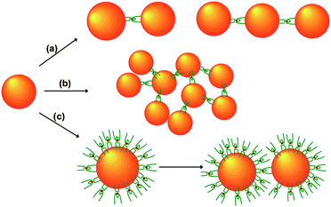 | ||
| Fig. 4 (a) At low AuNP:1 ratios, complex 1 assembles AuNPs into discrete dimers and trimers. (b) At intermediate AuNP:1 ratios, larger aggregates of AuNPs are induced to form. (c) When the AuNP:1 ratio exceeds a critical point, 1 forms a passivating monolayer on the surface of the AuNPs. Aggregation of these passivated AuNPs occurs relatively slowly. | ||
The inhibition of aggregation at high loadings of the linker rules out the possibility that electrostatic screening effects due to the charged nature of 1 are responsible for the aggregation of NPs at lower loadings. Furthermore, 1 is present at nanomolar concentrations, which contrasts with the ∼10 mM concentration required for salts such as KCl to aggregate NPs.14 Irreversible flocculation of the passivated AuNPs is eventually observed (Fig. 4c). The slow kinetics of this process (compared to the assembly of citrate-coated AuNPs) is consistent with the requirement to displace 1 from the AuNP surface.
The study was extended to examine the versatility of 1 for the formation of interlocked assemblies of other types of nanoparticles. Small (ca. 4 nm) AuNPs coated with a layer of PEGylated-thiol ligands were investigated. TEM and electronic absorption spectra show that aggregation takes place, the extent of which is controlled by the amount of added 1 (Fig. S10 and S11†). This is an important finding as these AuNPs are much more stable towards nonspecific aggregation than large citrate-coated AuNPs, therefore they should be more amenable to separation by techniques such as centrifugation or gel-permeation chromotography.6,9 This opens the door to the isolation and study of discrete, monodisperse assembliese.g., dimers and trimers. Furthermore, since these small AuNPs have a low ζ potential, these experiments confirm that the nanoparticle aggregation occurs as a consequence of gold–thiol bonding interactions between 1 and the NPs rather than as a consequence of electrostatic effects. This is in accord with expectations based on a significant body of literature.4
Similarly, we found that catenated assemblies of silver nanoparticles (AgNPs) could be prepared using 1 as a linker (Fig. 5 and S12†). Notably, although present in only nanomolar concentration, an intense Raman spectrum of 1 is obtained directly from these samples. Since the assembly of the AgNPs is induced by 1 itself, the need for additional aggregating agents14 to generate electromagnetic hotspots is obviated.
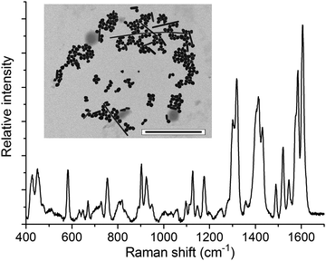 | ||
| Fig. 5 SERS spectrum of AgNPs aggregated by 1 (λexc = 514.5 nm). The inset is a representative TEM image (scale bar = 1000 nm). | ||
In summary, we have successfully realized the catenation of gold and silver NPs and three complementary experimental techniques have been employed to develop a comprehensive picture of these mechanically interlocked NP assemblies. One particularly exciting feature of these assemblies is their extremely intense Raman spectra, which can potentially be exploited for sensing applications. If they can be demetalated (i.e. the copper(I) ion removed from the linker), the arrays described herein are potentially very powerful sensors for the detection of copper(I) ions in aqueous environments. We are actively exploring methods for the demetalation of these arrays though this is particularly challenging goal given that cyanide ions, which are typically employed for the demetalation of copper(I)-based catenanes, are also known to etch AuNPs.22 It is possible that NP etching may be circumvented by erecting a barrier between the colloid surface and the cyanide ions, for example by using long passivating ligands on the surface of the NPs and/or cross-linking these ligands by polymerization reactions.23
Notes and references
- S. K. Ghosh and T. Pal, Chem. Rev., 2007, 107, 4797–4862 CrossRef CAS.
- G. A. DeVries, M. Brunnbauer, Y. Hu, A. M. Jackson, B. Long, B. T. Neltner, O. Uzun, B. H. Wunsch and F. Stellacci, Science, 2007, 315, 358–361 CrossRef CAS.
- (a) S. I. Lim and C.-J. Zhong, Acc. Chem. Res., 2009, 42, 798–808 CrossRef CAS; (b) C. J. Murphy, A. M. Gole, S. E. Hunyadi, J. W. Stone, P. N. Sisco, A. Alkilany, B. E. Kinard and P. Hankins, Chem. Commun., 2008, 544–557 RSC.
- (a) F. Westerlund and T. Bjørnholm, Curr. Opin. Colloid Interface Sci., 2009, 14, 126–134 CrossRef CAS; (b) G. Schmid and U. Simon, Chem. Commun., 2005, 697–710 RSC.
- (a) I. E. Sendroiu, D. J. Schiffrin and J. M. Abad, J. Phys. Chem. C, 2008, 112, 10100–10107 CrossRef CAS; (b) F. P. Zamborini, M. C. Leopold, J. F. Hicks, P. J. Kulesza, M. A. Malik and R. W. Murray, J. Am. Chem. Soc., 2002, 124, 8958–8964 CrossRef CAS.
- (a) I. Hussain, M. Brust, J. Barauskas and A. I. Cooper, Langmuir, 2009, 25, 1934–1939 CrossRef CAS; (b) I. S. Lim, C. Vaiana, Z.-Y. Zhang, Y.-J. Zhang, D.-L. An and C.-J. Zhong, J. Am. Chem. Soc., 2007, 129, 5368–5369 CrossRef.
- (a) C. M. Niemeyer and G. Simon, Eur. J. Inorg. Chem., 2005, 3641–3655 CrossRef CAS; (b) A. P. Alivisatos, K. P. Johnsson, X. Peng, T. E. Wilson, C. J. Loweth, M. P. Bruchez and P. G. Schultz, Nature, 1996, 382, 609–611 CrossRef CAS; (c) A. J. Mastroianni, S. A. Claridge and A. P. Alivisatos, J. Am. Chem. Soc., 2009, 131, 8455–8459 CrossRef CAS.
- M. A. Olson, A. Coskun, R. Klajn, L. Fand, K. D. Sanjeev, K. P. Browne, B. A. Grzybowski and J. F. Stoddart, Nano Lett., 2009, 9, 3185–3190 CrossRef CAS.
- C.-L. Chen, P. Zhang and N. L. Rosi, J. Am. Chem. Soc., 2008, 130, 13555–13557 CrossRef CAS.
- R. Levy, Z. Wang, L. Duchesne, R. C. Doty, A. I. Cooper, M. Brust and D. G. Fernig, ChemBioChem, 2006, 7, 592–594 CrossRef CAS.
- (a) G. Chen, Y. Wang, L. H. Tan, M. Yang, L. S. Tan, Y. Chen and H. Chen, J. Am. Chem. Soc., 2009, 131, 4218–4219 CrossRef CAS; (b) J. P. Novak, C. Nickerson, S. Franzen and D. L. Feldheim, Anal. Chem., 2001, 73, 5758–5761 CrossRef CAS.
- T. Dadosh, Y. Gordin, R. Krahne, I. Khivrich, D. Mahalu, V. Frydman, J. Sperling, A. Yacoby and I. Bar-Joseph, Nature, 2005, 436, 677–680 CrossRef CAS.
- (a) Molecular Machines and Motors, ed. J.-P. Sauvage, Springer-Verlag, Berlin, 2010 Search PubMed; (b) J. D. Crowley, S. M. Goldup, A.-L. Lee, D. A. Leigh and R. T. Burney, Chem. Soc. Rev., 2009, 38, 1530–1541 RSC; (c) C. Dietrich-Buchecker, J.-P. Sauvage and J.-M. Kern, J. Am. Chem. Soc., 1989, 111, 7791–7800 CrossRef CAS; (d) C. Dietrich-Buchecker and J.-P. Sauvage, J. Am. Chem. Soc., 1984, 106, 3043–3045 CrossRef CAS.
- (a) E. C. Le Ru and P. G. Etchegoin, Principles of Surface-Enhanced Raman Spectroscopy, Elsevier, Amsterdam, 2008 Search PubMed; (b) R. Jin, Angew. Chem., Int. Ed., 2010, 49, 2826–2829 CAS.
- (a) G. Chen, Y. Wang, M. Yang, J. Xu, S. J. Goh, M. Pan and H. Chen, J. Am. Chem. Soc., 2010, 132, 3644–3645 CrossRef CAS; (b) J. P. Camden, J. A. Dieringer, Y. Wang, D. J. Masiello, L. D. Marks, G. C. Schatz and R. P. V. Duyne, J. Am. Chem. Soc., 2008, 130, 12616–12617 CrossRef CAS.
- (a) F. Arico, P. Mobian, J.-M. Kern and J.-P. Sauvage, Org. Lett., 2003, 5, 1887–1890 CrossRef CAS; (b) M. Weck, B. Mohr, J.-P. Sauvage and R. H. Grubbs, J. Org. Chem., 1999, 64, 5463–5471 CrossRef.
- S. Provencher, Comput. Phys. Commun., 1982, 27, 229–242 CrossRef.
- B. J. Frisken, Appl. Opt., 2001, 40, 4087–4091 CrossRef CAS.
- W. Halss, N. T. K. Thanh, J. Aveyard and D. G. Fernig, Anal. Chem., 2007, 79, 4215–4221 CrossRef CAS.
- S. J. Lind, K. C. Gordon and M. R. Waterland, J. Raman Spectrosc., 2008, 39, 1556–1567 CrossRef CAS.
- G. H. Woehrle, L. O. Brown and J. E. Hutchison, J. Am. Chem. Soc., 2005, 127, 2172–2183 CrossRef CAS.
- L.-o. Srisombat, J.-S. Park, S. Zhang and T. R. Lee, Langmuir, 2008, 24, 7750–7754 CrossRef CAS.
- C. Krueger, S. Agarwal and A. Greiner, J. Am. Chem. Soc., 2008, 130, 2710–2711 CrossRef.
Footnotes |
| † Electronic supplementary information (ESI) available: Full details of synthetic procedures and nanoparticle aggregation experiments. See DOI: 10.1039/c0nr00801j |
| ‡ Full experimental details are provided in the ESI†. |
| This journal is © The Royal Society of Chemistry 2011 |