Fabrication of hybrids based on graphene and metal nanoparticles by in situ and self-assembled methods
Fu-An
He
a,
Jin-Tu
Fan
*a,
Fei
Song
b,
Li-Ming
Zhang
b and
Helen
Lai-Wa Chan
c
aInstitute of Textiles and Clothing, The Hong Kong Polytechnic University, Hung Hom, Kowloon, Hong Kong. E-mail: tcfanjt@inet.polyu.edu.hk; Fax: +852 2773 1432
bKey Laboratory for Designed Synthesis and Application of Polymer Materials, Sun Yat-Sen University, Guangzhou, 510275, China
cDepartment of Applied Physics and Materials Research Centre, The Hong Kong Polytechnic University, Hung Hom, Kowloon, Hong Kong
First published on 24th January 2011
Abstract
In this work, we developed two novel strategies to attach metal nanoparticles (Au and Ag) to the surface of graphene nanosheets, in which graphene oxide was first modified by the linking molecule (3-mercaptopropyl)triethoxysilane and then subjected to different treatments including in situ and self-assembled techniques. The synthesis processes and the resulting hybrids were investigated by ultraviolet-visible measurements, scanning electron microscopy, transmission electron microscopy, and X-ray photoelectron spectroscopy. It was found that both approaches could effectively immobilize metal nanoparticles onto a graphene surface, and that better distribution and size control of metal nanoparticles were obtained by the self-assembled method. Moreover, we prepared poly(vinylidene fluoride)/graphene–Ag nanocomposites by a solution blending method. The AC conductivity of the resulting nanocomposites could be increased significantly when the loading amount of graphene–Ag was only 2 wt%. We expect that such graphene–metal nanoparticle hybrids may be potentially useful in composite reinforcement, sensors, and electronic devices.
Introduction
Metal nanoparticles (MNPs), such as Au and Ag, have stimulated intense interest because of their special optical and electrical properties as well as their high catalytic activity.1 In recent years, MNPs have been incorporated on various supports including silica nanofiber, electrospun membrane, carbon nanosphere, and carbon nanotubes (CNTs) to form new materials for the purpose of exploring their applications.2–8 Especially, the construction of CNT–MNP heterostructures with novel functionalities has attracted great attention since such hybrids can be potentially applied in many areas, for example, chemical sensor, biosensor, heterogeneous catalyst, and nanoelectronics.9–17 In general, there are two common approaches for the preparation of CNT–MNP hybrids: (1) reducing the metal ionic precursor in a CNT solution along with simultaneous deposition of resultant MNPs on CNT surface (in situ method), and (2) dispersing pre-synthesized MNPs in a CNT solution followed by the adsorption of MNPs on the CNT surface (self-assembled method).Graphene, a new carbon-based material with similar fascinating properties like CNTs, has become a hot topic recently due to its high mechanical strength, good thermal conductivity, and special electrical property.18 It is well known that graphene nanosheets can be easily obtained through a chemical route, which involves the reduction of exfoliated graphene oxide (GO) by reducing agents to remove oxygenated functional groups.19–24 Moreover, owing to its unique one-atom thickness and two-dimensional plane structure, graphene has larger surface area than that of CNTs and therefore may be an ideal alternative to the expensive CNTs for supporting MNPs. It can be anticipated that such a novel graphene–MNP hybrid will be another promising functional material displaying interesting properties for nanotechnology application. Very recently, several pioneering papers have reported the synthesis and characterization of graphene–MNP hybrids.25–32 For example, Kamat et al. use chemically modified graphene sheets to support Au nanoparticles with diameters of 3–30 nm, in which the Au nanoparticles were synthesized using chemical reduction of AuCl4− by NaBH4 in a octadecylamine-modified graphene suspension.25 Hassan et al. developed a simultaneous reduction method to prepare graphene–MNP hybrids assisted by microwave irradiation using a variety of reducing agents in either aqueous or organic media.29 He et al. prepared GO–Fe3O4 hybrids by a two-step covlent method. They found that the obtained GO–Fe3O4 hybrids could be reduced to form graphene–Fe3O4 hybrids by NaBH4.31 Quintana et al. modified few-layer graphenes using the 1,3-dipolar cycloaddition of azomethine ylides. The amino functional groups attached to graphene sheets could effectively bind gold nanorods by the self-assembled method.32 However, it is still very necessary to find the best conditions for the fabrication of graphene–MNP hybrids by exploring different procedures. Furthermore, although a number of researchers have proposed methods for the preparation of graphene–MNPs by the in situ method, only a small amount of work has been carried out by using the self-assembled method up to now.
In this work, we have developed two novel strategies to immobilize MNPs (Au and Ag) on the surface of graphene nanosheets. As shown in Fig. 1, GO was first functionalized with the linking molecule (3-mercaptopropyl)triethoxysilane (MPTES) to improve the affinity between Au and graphene because the MPTES grafted on the graphene surface can effectively bind the Au nanoparticles by its –SH functional group,13–17 and then subjected to different treatments including in situ and self-assembled techniques. Moreover, we prepared nanocomposites containing poly(vinylidene fluoride) (PVDF) and graphene–Ag by a solution blending method and the AC conductivity of the resulting nanocomposites were studied.
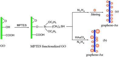 | ||
| Fig. 1 Schematic illustration of graphene–Au hybrids formation: (a) self-assembled method, (b) in situ method. | ||
Experimental
Chemicals
The natural flake graphite used to prepare GO was provided by Qingdao Dingding graphite products factory. (3-Mercaptopropyl)triethoxysilane, HAuCl4, hydrazine, dimethylformamide (DMF), and other chemical reagents were purchased from Dongzheng Chemical Corporation without any further treatment.Preparation
Graphene oxide (GO) was synthesized as reported by Liet al.19 GO was modified with (3-mercaptopropyl)triethoxysilane to obtain MPTES-functionalized GO according to the literature.33 The graphene–Au hybrids were prepared by in situ and self-assembled methods. In the in situ method, 0.4 mL of sodium citrate solution (0.025 M), 10 ml of MPTES-functionalized GO solution (1 mg ml−1), and 140 μl of ammonia solution (28 wt%) were added to 39.6 mL of HAuCl4 aqueous solution (2.5 × 10⁻⁴ M) in sequence and then the resultant solution was subjected to ultrasonication for 10 min. Next, hydrazine was added to the solution for the reduction of MPTES-functionalized GO and HAuCl4. The weight ratio of hydrazine to MPTES-functionalized GO was about 7![[thin space (1/6-em)]](https://www.rsc.org/images/entities/char_2009.gif) :
:![[thin space (1/6-em)]](https://www.rsc.org/images/entities/char_2009.gif) 10. The reduction was carried out at 95 °C for 1 h. In the self-assembled method, 10 mg of MPTES-functionalized GO was dispersed in 20 ml of DMF by sonication for 5 h. After that hydrazine was added to the solution for the reduction of MPTES-functionalized GO. The weight ratio of hydrazine to MPTES-functionalized GO was about 1
10. The reduction was carried out at 95 °C for 1 h. In the self-assembled method, 10 mg of MPTES-functionalized GO was dispersed in 20 ml of DMF by sonication for 5 h. After that hydrazine was added to the solution for the reduction of MPTES-functionalized GO. The weight ratio of hydrazine to MPTES-functionalized GO was about 1![[thin space (1/6-em)]](https://www.rsc.org/images/entities/char_2009.gif) :
:![[thin space (1/6-em)]](https://www.rsc.org/images/entities/char_2009.gif) 1. The reduction was carried out at 95 °C for 1 h in a silicon oil bath assisted with mild ultrasonication. The Au nanoparticles with well-defined size (2–5 nm) were prepared according to the method reported in the literature.11 Subsequently, 40 ml of a Au nanoparticle solution (2.5 × 10⁻⁴ M) was added to the reduced graphene solution and stirred for 3 h at room temperature. In both methods, the suspensions containing graphene nanosheets decorated with Au nanoparticles were centrifuged, washed with deionic water, and then dried to obtain the graphene–Au hybrids. Graphene–Ag hybrids were synthesized by the in situ and self-assembled methods which were similar to the synthesis processes of graphene–Au hybrids. PVDF/graphene–Ag nanocomposites were fabricated by blending PVDF with graphene–Ag obtained from self-assembled method in DMF solvent. Three samples with graphene–Ag concentrations of 0.5, 1, and 2 wt% were prepared.
1. The reduction was carried out at 95 °C for 1 h in a silicon oil bath assisted with mild ultrasonication. The Au nanoparticles with well-defined size (2–5 nm) were prepared according to the method reported in the literature.11 Subsequently, 40 ml of a Au nanoparticle solution (2.5 × 10⁻⁴ M) was added to the reduced graphene solution and stirred for 3 h at room temperature. In both methods, the suspensions containing graphene nanosheets decorated with Au nanoparticles were centrifuged, washed with deionic water, and then dried to obtain the graphene–Au hybrids. Graphene–Ag hybrids were synthesized by the in situ and self-assembled methods which were similar to the synthesis processes of graphene–Au hybrids. PVDF/graphene–Ag nanocomposites were fabricated by blending PVDF with graphene–Ag obtained from self-assembled method in DMF solvent. Three samples with graphene–Ag concentrations of 0.5, 1, and 2 wt% were prepared.
Characterization
X-Ray photoelectron spectroscopy (XPS) spectra were obtained using the ESCALAB 250 X-ray Photoelectron Spectroscopy/ESCA equipment. A JEOL JEM-2010 TEM was employed to observe the structure of graphene–MNP hybrids. The scanning electron microscopy (SEM) image and energy-dispersive X-ray spectroscopy (EDS) spectra were obtained on the JEOL JSM-6490 equipment equipped with an energy-dispersive X-ray analysis system. UV–vis characterization was conducted on Perkin-Elmer Lambda 18 equipment. AC conductivities of the samples were measured using an Agilent 4294 A impedance analyzer in the frequency range of 103–107 Hz at room temperature.Results and discussion
In the in situ method, both MPTES-functionalized GO and AuCl4− were reduced simultaneously by hydrazine at 95 °C in a one-pot reaction to obtain the graphene–Au hybrids. Ultraviolet-visible (UV-vis) absorption spectroscopy was used to trace the reduction process as shown in Fig. 2. Before reduction, the spectrum of GO–AuCl4−water solution presents two characteristic peaks related to GO at 227 and 300 nm, which correspond respectively to π→π* transitions of aromatic C–C bonds and n→π* transitions of C![[double bond, length as m-dash]](https://www.rsc.org/images/entities/char_e001.gif) O bonds. After reduction began, the absorption peak of GO dispersion at 227 nm gradually redshifted to 262 nm with reaction time and the shoulder absorption peak at 300 nm disappeared, which indicates that the electronic conjugation within the graphene nanosheets has been restored by the reduction of hydrazine.19,24–26 It is also noteworthy that a new peak at 540 nm occurred and gradually redshifted to 550 nm during the reduction process. This new peak can be assigned to the surface plasmon resonance (SPR) absorption band of Au nanoparticles, suggesting the successful reduction of AuCl4− to Au nanoparticles.3,34 It is known that the position of SPR band depends on the nanoparticles size and the distance between the nanoparticles. The higher SPR peak value means the closer interparticle proximity or the formation of bigger particle aggregation.13 In a control experiment, a homogenous solution of Au nanoparticles was synthesized under the same reaction conditions without the addition of MPTES-functionalized GO, and its SPR absorption peak was observed at 518 nm. This result implies that, for the in situ method, Au nanoparticles were in close proximity with each other upon the reduction process and even some agglomerations or big particles have formed and deposited on the graphene surface.
O bonds. After reduction began, the absorption peak of GO dispersion at 227 nm gradually redshifted to 262 nm with reaction time and the shoulder absorption peak at 300 nm disappeared, which indicates that the electronic conjugation within the graphene nanosheets has been restored by the reduction of hydrazine.19,24–26 It is also noteworthy that a new peak at 540 nm occurred and gradually redshifted to 550 nm during the reduction process. This new peak can be assigned to the surface plasmon resonance (SPR) absorption band of Au nanoparticles, suggesting the successful reduction of AuCl4− to Au nanoparticles.3,34 It is known that the position of SPR band depends on the nanoparticles size and the distance between the nanoparticles. The higher SPR peak value means the closer interparticle proximity or the formation of bigger particle aggregation.13 In a control experiment, a homogenous solution of Au nanoparticles was synthesized under the same reaction conditions without the addition of MPTES-functionalized GO, and its SPR absorption peak was observed at 518 nm. This result implies that, for the in situ method, Au nanoparticles were in close proximity with each other upon the reduction process and even some agglomerations or big particles have formed and deposited on the graphene surface.
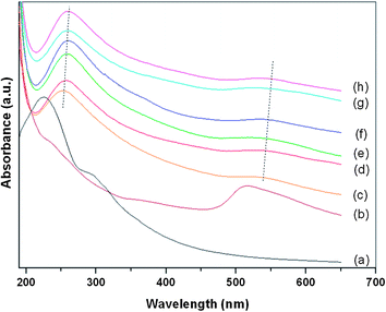 | ||
| Fig. 2 UV-Vis absorption spectra of (a) GO–AuCl4−water solution, (b) Au NPs solution prepared under similar reaction condition of preparing GO–Au nanocomposites by in situ method, (c)–(h) Reduced GO–AuCl4−water solution as a function of reaction time (from 10 to 60 min, time interval: 10 min). | ||
The scanning electron microscopy (SEM) image for the graphene–Au hybrids (see Fig. 3) prepared by the in situ method shows that the crumpled sheets of graphene aggregated together to form disordered solid, which is similar to the result reported by Nethravathi et al.35 Furthermore, the presence of Au element in the hybrids is confirmed by the energy-dispersive X-ray spectrum (EDS), as shown in Fig. 3. The EDS also reveals the existence of other elements on the graphene surface including C, O, S and Si. While the C and O signals mainly originated from the graphene, the S and Si signals were obtained from the linking molecule MPTES. Moreover, it can be found that oxygen content has decreased greatly from 42.7 to 13.1 wt% after reduction. These observations imply that both MPTES-functionalized GO and AuCl4− were reduced by hydrazine simultaneously to form graphene and Au, and the in situ synthesized Au could deposit on the surfaces of graphene.4
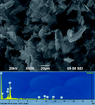 | ||
| Fig. 3 SEM and EDS analysis of graphene–Au hybrids prepared by in situ method. | ||
The X-ray photoelectron spectroscopy (XPS) characterization also confirms the reduction of oxygen functional groups in GO and AuCl4− ions by in situ method. The C1s spectrum of GO with peak-fitting curves is presented in Fig. 4a. The peaks at 284.7, 285.4, 286.9, 288.1, and 289.3 eV can be assigned to carbon atoms in C![[double bond, length as m-dash]](https://www.rsc.org/images/entities/char_e001.gif) C, C–C, C–O, C
C, C–C, C–O, C![[double bond, length as m-dash]](https://www.rsc.org/images/entities/char_e001.gif) O and O–C
O and O–C![[double bond, length as m-dash]](https://www.rsc.org/images/entities/char_e001.gif) O, respectively.36–38 This result suggests that there are large amounts of functional groups such as hydroxyl, carbonyl, carbonate and quinone on the GO surface. In comparison to GO, the C1s spectrum of graphene–Au hybrids (see Fig. 4b) obviously exhibited a decreased intensity for peaks corresponding to C–O and C
O, respectively.36–38 This result suggests that there are large amounts of functional groups such as hydroxyl, carbonyl, carbonate and quinone on the GO surface. In comparison to GO, the C1s spectrum of graphene–Au hybrids (see Fig. 4b) obviously exhibited a decreased intensity for peaks corresponding to C–O and C![[double bond, length as m-dash]](https://www.rsc.org/images/entities/char_e001.gif) O groups so that the peaks associated with C
O groups so that the peaks associated with C![[double bond, length as m-dash]](https://www.rsc.org/images/entities/char_e001.gif) C and C–C became predominant, indicating effective deoxygenation of GO. Besides, an additional component of C1s at 286.1 eV and a new peak at 400.0 eV were observed, which can be ascribed to the formation of C–N bonding because some carbon atoms are replaced by nitrogen during reduction when we used hydrazine as reducing agent.20–22 On the other hand, as show in Fig. 4c, the Au 4f spectrum for graphene–Au nanocomposites can be detected and the binding energies of 4f7/2 and 4f5/2 electrons for Au are identified to be 84.4 and 88.0 eV respectively.30
C and C–C became predominant, indicating effective deoxygenation of GO. Besides, an additional component of C1s at 286.1 eV and a new peak at 400.0 eV were observed, which can be ascribed to the formation of C–N bonding because some carbon atoms are replaced by nitrogen during reduction when we used hydrazine as reducing agent.20–22 On the other hand, as show in Fig. 4c, the Au 4f spectrum for graphene–Au nanocomposites can be detected and the binding energies of 4f7/2 and 4f5/2 electrons for Au are identified to be 84.4 and 88.0 eV respectively.30
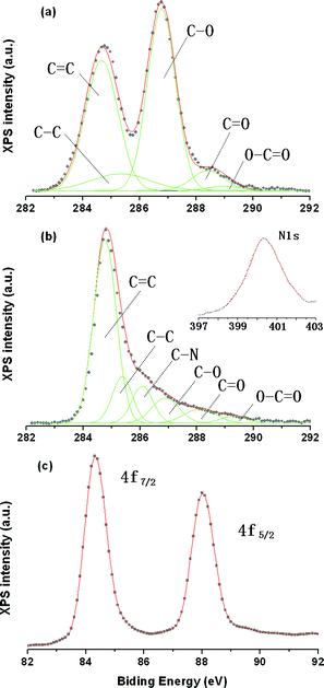 | ||
| Fig. 4 C1s XPS spectra of (a) GO and (b) graphene–Au hybrids prepared by the in situ method, (c) Au4f XPS spectrum of graphene–Au hybrids prepared by the in situ method. | ||
Transmission electron microscopy (TEM) was used to verify the formation of graphene–Au hybrid by in situ method. As shown in Fig. 5, roughly spherical Au nanoparticles with diameters mainly in the range of 2–10 nm are attached on the surface of graphene. Nevertheless, some aggregations and larger particles (about 40 nm) can also be observed, which is in agreement with the UV-vis result. According to our observations, the in situ method is a simple and effective strategy to fabricate graphene–Au hybrids. Hoverer, this method seems difficult to control the size of the Au nanoparticles and their interaction with the graphene nanosheets, which can be explained as follows. During the reduction process, Au nuclei preferentially deposited and grew on the GO surfaces rather than in solution owing to the strong interaction between the AuCl4− ions and the functional groups of GO.39 In this heterogeneous system, many unstable and complex factors may influence the reaction environment. Such factors include wrinkled GO surface, high reaction temperature that is necessary for the reduction of GO, interactions between Au nuclei and various functional groups (–SH, –OH, –COOH, –C![[double bond, length as m-dash]](https://www.rsc.org/images/entities/char_e001.gif) O, C–O–C), gradual deoxygenation of GO upon reaction time, etc. Therefore, the growth of Au nanoparticles can not be precisely controlled by the in situ method, which results in a broad particle size distribution. Our observation was similar to that reported by other groups.25,29,30
O, C–O–C), gradual deoxygenation of GO upon reaction time, etc. Therefore, the growth of Au nanoparticles can not be precisely controlled by the in situ method, which results in a broad particle size distribution. Our observation was similar to that reported by other groups.25,29,30
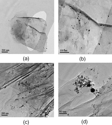 | ||
| Fig. 5 TEM images of graphene–Au hybrids prepared by in situ method at (a), (c) low magnification and (b), (d) high magnification. | ||
In the self-assembled method, MPTES-functionalized GO was first reduced by hydrazine in DMF solvent, followed by mixing with pre-synthesized Au nanoparticles at room temperature to obtain graphene–Au hybrids. That the size and morphology of the nanoparticle can be controlled in advance gives the self-assembled method an advantage over the in situ method. Here Au nanoparticles with well-defined size in the range of 2–5 nm were used. These Au nanoparticles were prepared by the reduction of homogenous Au ionic solution using sodium citrate as stabilizer and NaBH4 as reducing agent.
C1s XPS spectrum of the MPTES-functionalized GO after reduction by hydrazine in DMF is presented in Fig. 6a. The result shows that peaks assigned to oxygen-containing functional groups were significantly decreased when compared with the C1s spectrum of GO, suggesting considerable deoxygenation of MPTES-functionalized GO during the reduction process. The deoxygenation of MPTES-functionalized GO is further confirmed by the EDS analysis (see Fig. 6b). Fig. 6c shows the digital photograph of MPTES-functionalized GO suspensions in DMF before and after reduction by hydrazine. The color of solution changed from brown to black upon reduction, indicating successful reduction of GO to graphene.
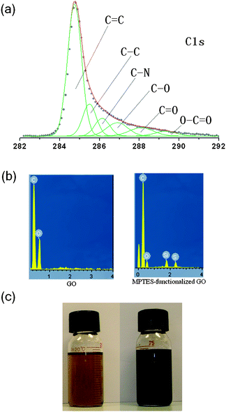 | ||
| Fig. 6 (a) C1s XPS spectrum of MPTES-functionalized GO, (b) EDS of GO and MPTES-functionalized GO, (c) DMF solution of MPTES-functionalized GO before (left) and after (right) reduction. | ||
The suspension of reduced graphene in polar solvents can remain stable for a long time, which is beneficial for further processing and composite fabrication. Fig. 7 shows the UV-vis spectra of reduced graphene nanosheets in DMF at different concentrations ranging from 350 to 700 nm, and the absorption intensities at 500 nm were plotted as a function of graphene concentrations. It can be seen that the plotting result follows the Lambert-Beer's law and yields a straight line. Accordingly, the extinction coefficient value was calculated to be 14.82 (mg mL−1)−1 cm−1. We also find that the reduced graphene can be dispersible in other polar solvents, such as N-methyl-2-pyrrolidone and dimethylacetamide, with similar extinction coefficient values.
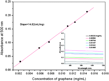 | ||
| Fig. 7 UV-Vis spectra of the MPTES-functionalized GO at different concentrations in DMF (inset) and absorbance of the MPTES-functionalized GO in DMF at 500 nm vs. its concentrations. | ||
Fig. 8 reveals TEM images of a graphene nanosheet decorated with Au nanoparticles by the self-assembled method. The result shows that lots of individual Au nanoparticles with spherical shape distribute homogeneously on the surface of the graphene nanosheet. The sizes of Au nanoparticles on the graphene surface vary from 2 to 5 nm without heavy aggregation, indicating that the size and morphology of pre-synthesized Au nanoparticles did not change obviously after immobilization.
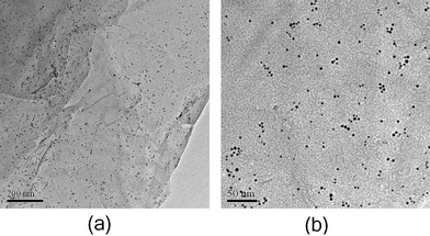 | ||
| Fig. 8 TEM images of graphene–Au hybrids prepared by self-assembled method at (a) low magnification, (b) high magnification. | ||
It seems that self-assembled method can prepare more well-dispersed MNPs with uniform size and morphology on the graphene surface when compared with in situ method. To support this assumption, we also prepare graphene–Ag hybrids by the two methods mentioned above. As shown in Fig. 9a and c, a better dispersion of Ag nanoparticles on graphene nanosheets can be obtained by the self-assembled method. According to TEM images at high magnification presented in Fig. 9b and d, spherical Au nanoparticles can be supported on the graphene surface by the self-assembled method, whereas the shape of Ag nanoparticles obtained from in situ method is very irregular, which can be ascribed to the complex reaction process. It is well known that MNPs with well-defined structure on CNTs surface are an important factor for chemical, electrochemical, and photochemical applications.38 Until now most research has been focused on the preparation of graphene–MNPs by the in situ method due to its convenience and efficiency; despite this, we believe that the self-assembled method might be more versatile because size and morphology (wires, spheres, rods, polyhedral plates, and so forth) of the decorated metal nanocrystals can be easily controlled in this case.32
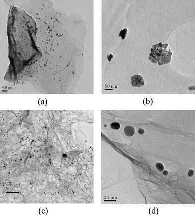 | ||
| Fig. 9 TEM images of graphene–Ag hybrids prepared by the in situ method at (a) low magnification, (b) high magnification, and the self-assembled method at (c) low magnification, (d) high magnification. | ||
PVDF is an important thermoplastic polymer and has been widely investigated because of its high dielectric permittivity, pyroelectricity, and piezoelectricity. Conductive nano-fillers, such as CNTs or CNTs–Ag, have been used to enhance the electric properties of PVDF.40 Here PVDF/graphene–Ag nanocomposites were prepared by a solution method using DMF as a solvent. Fig. 10 shows the AC conductivity of PVDF and PVDF/graphene–Ag nanocomposites with different graphene–Ag loading amounts as a function of frequency. When the graphene–Ag contents were 0.5 and 1 wt%, the enhancements of AC conductivity were slight and the AC conductivity increased almost linearly with the increase of frequency. When the graphene–Ag content was 2 wt%, the AC conductivity increased significantly and was almost independent of the change of frequency within a low frequency range. This effective improvement of AC conductivity can be ascribed to the synergistic effect of the hybridization of graphene with Ag nanoparticles.41,42 Using 103 Hz as a point of comparison, the AC conductivities for PVDF and its nanocomposites containing 0.5, 1, and 2 wt% graphene–Ag were found to be 1.07 × 10⁻⁷, 1.40 × 10⁻⁷, 1.57 × 10⁻⁷, and 5.46 × 10⁻⁴ S m−1, respectively. This obvious conductor-to-insulator transition can be explained by the percolation theory.40,43 For the nanocomposite consisting of polymer and conductive filler, when the content of conductive filler is low, the enhancement of conductivity in nanocomposite is slight because the filler cannot effectively contact with one another to form the electrical path. When the content of conductive filler increases to a critical point (percolation threshold), filler particles form a percolating conductive network throughout the nanocomposite and then an abrupt increment in the electrical conductivity of nanocomposite can be observed.
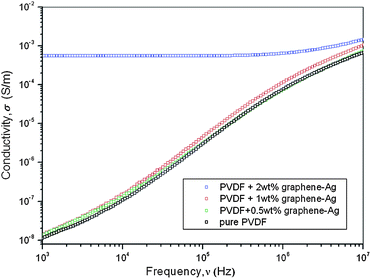 | ||
| Fig. 10 Dependence of AC conductivities on the frequency for PVDF and its PVDF/grapheme–Ag nanocomposites. | ||
Conclusions
In conclusion, we have demonstrated two strategies to prepare graphene–MNP hybrids including in situ and self-assembled methods. The results showed that both approaches could effectively immobilize MNPs onto graphene surface and the better distribution and size control of MNPs was obtained by self-assembled method. In addition, the incorporation of graphene–Ag hybrids into PVDF matrix could significantly increase its AC conductivity when the loading amount of graphene–Ag was only 2 wt%. We expect that the graphene–MNP hybrids can be useful for various applications such as composite reinforcement, sensors, and electronic devices.Acknowledgements
The authors would like to acknowledge the funding support of Hong Kong Polytechnic University in the form of a Niche Area Project (1-BB82), and the Postdoctoral Fellowship of Hong Kong Polytechnic University (Project No: G-YX1K).Notes and references
- K. Watanabe, D. Menzel, N. Nilius and J. Freund, Chem. Rev., 2006, 106, 4301 CrossRef CAS.
- S. Z. Zhang, W. H. Ni, X. S. Kou, M. H. Yeung, L. D. Su, J. F. Wang and C. H. Yan, Adv. Funct. Mater., 2008, 17, 3258.
- H. Dong, D. Wang, G. Sun and J. P. Hinestroza, Chem. Mater., 2008, 20, 6627 CrossRef CAS.
- R. J. Cui, C. Liu, M. J. Shen, Q. Gao, J. Q. Zhu and Y. H. Chen, Adv. Funct. Mater., 2008, 18, 2197 CrossRef CAS.
- X. H. Peng, J. Y. Chen, J. A. Misewich and S. S. Wong, Chem. Soc. Rev., 2009, 38, 1076 RSC.
- A. Zamudio, A. L. Elias, J. A. Rodriguez-Manzo, F. Lopez-Urias, G. Rodriguez-Gattorno, F. Lupo, M. Ruhle, J. D. Smith, H. Terrones, D. Diaz and M. Terones, Small, 2006, 2, 346 CrossRef CAS.
- X. L. Li, Y. Q. Liu, L. Fu, C. Cao, D. C. Wei and Y. Wang, Adv. Funct. Mater., 2006, 16, 2431 CrossRef CAS.
- C. H. Tseng and C. Y. Chen, Nanotechnology, 2007, 19, 035606.
- R. Y. Zhang and X. M. Wang, Chem. Mater., 2007, 19, 976 CrossRef CAS.
- S. Sanchez, H. Fabregas, H. Iwai and M. Pumera, Small, 2009, 5, 795 CrossRef CAS.
- Y. Y. Ou, M. H. Huang, H. Iwai and M. Pumera, J. Phys. Chem. B, 2006, 110, 2031 CrossRef CAS.
- K. Y. Jiang, A. Eitan, L. S. Schadler, P. M. Ajayan, R. W. Siegel, N. Grobert, M. Mayne, M. Reyes-Reyes, M. H. Terrones and M. Terrones, Nano Lett., 2003, 3, 275 CrossRef CAS.
- J. P. Hu, J. H. Shi, S. P. Li, Y. J. Qin, Z. S. Guo, Y. L. Song and D. B. Zhu, Chem. Phys. Lett., 2005, 401, 352 CrossRef CAS.
- L. Q. Liu, T. X. Wang, J. X. Li, Z. X. Guo, L. M. Dai, D. Q. Zhang and D. B. Zhu, Chem. Phys. Lett., 2003, 367, 747 CrossRef CAS.
- T. Sainsbury, T. Ikuno, D. Okawa, D. Pacile, J. M. J. Frechet and A. Zettl, J. Phys. Chem. C, 2007, 111, 12992 CrossRef CAS.
- R. Zanella, E. V. Basiuk, P. Santiago, V. A. Basiuk, E. Mireles, I. Puente-Lee and J. M. Saniger, J. Phys. Chem. B, 2005, 109, 16290 CrossRef CAS.
- M. Bottini, A. Magrini, N. Rosato, A. Bergamaschi and T. Mustelin, J. Phys. Chem. B, 2006, 110, 13685 CrossRef CAS.
- S. Park and R. S. Ruoff, Nat. Nanotechnol., 2009, 4, 217 CrossRef CAS.
- D. Li, M. B. Muller, S. Gilje, R. B. Kaner and G. G. Wallace, Nat. Nanotechnol., 2008, 3, 101 CrossRef CAS.
- S. Park, J. H. An, R. D. Piner, I. W. Jung, D. X. Yang, A. Velamakanni, S. T. Nguyen and R. B. Kaner, Chem. Mater., 2008, 20, 6592 CrossRef CAS.
- S. Park, J. H. An, I. W. Jung, R. D. Piner, S. J. An, X. S. Li, A. Velamakanni and R. S. Ruoff, Nano Lett., 2009, 20, 1593 CrossRef.
- H. Bai, Y. X. Xu, L. Zhao, C. Li and G. Q. Shi, Chem. Commun., 2009, 19, 1667 Search PubMed.
- Y. X. Xu, H. Bai, G. W. Lu, C. Li and G. Q. Shi, J. Am. Chem. Soc., 2008, 130, 5856 CrossRef CAS.
- S. Villar-Rodil, J. I. Paredes, A. Martinez-Alonso and J. M. D. Tascon, J. Mater. Chem., 2009, 19, 3591 RSC.
- R. Muszynski, B. Seger and P. V. Kamat, J. Phys. Chem. C, 2008, 112, 5263 CrossRef CAS.
- B. S. Kong, J. X. Geng and H. T. Jung, Chem. Commun., 2009, 16, 2174 Search PubMed.
- C. Xu, X. Wang and J. W. Zhu, J. Phys. Chem. C, 2008, 112, 9841.
- A. B. Bourlinos, V. Georgakilas, R. Zboril, T. A. Steriotis and A. K. Stubos, Small, 2009, 5, 1841 CrossRef CAS.
- H. M. A. Hassan, V. Abdelsayed, A. E. R. S. Khder, K. M. AbouZeid, J. Terner, M. S. El-Shall, S. I. Al-Resayes and A. A. El-Azhary, J. Mater. Chem., 2009, 19, 3832 RSC.
- F. H. Li, H. F. Yang, C. S. Shan, Q. X. Zhang, D. X. Han, A. Ivaska and L. Niu, J. Mater. Chem., 2009, 19, 4022 RSC.
- F. A. He, J. T. Fan, D. Ma, L. M. Zhang, C. W. Leung and H. L. W. Chan, Carbon, 2010, 48, 3139 CrossRef CAS.
- M. Quintana, K. Spyrou, M. Grzelczak, W. R. Browne, P. Rudolf and M. Prato, ACS Nano, 2010, 4, 3527 CrossRef CAS.
- Y. Matsuo, T. Fukunaga, T. Fukutsuka and Y. Sugie, Carbon, 2004, 42, 2117 CrossRef CAS.
- X. Q. Fu, F. L. Bei, X. Wang, S. O'Brien and J. R. Lombardi, Nanoscale, 2010, 2, 1461 RSC.
- C. Nethravathi and M. Rajamathi, Carbon, 2008, 46, 2054.
- V. Datsyuk, M. Kalyva, K. Papagelis, J. Parthenios, D. Tasis, A. Siokou, I. Kallitsis and C. Galiotis, Carbon, 2008, 46, 833 CrossRef CAS.
- H. J. Shin, K. K. Kim, A. Benayad, S. M. Yoon, H. K. Park, I. S. Jung, M. H. Jin, H. K. Jeong, M. J. Kim, J. Y. Choi and Y. H. Lee, Adv. Funct. Mater., 2009, 19, 1987 CrossRef CAS.
- Y. Geng, S. J. Wang and J. K. Kim, J. Colloid Interface Sci., 2009, 336, 592 CrossRef CAS.
- J. W. Zhu, G. Y. Zeng, F. D. Nie, X. M. Xu, S. Chen, Q. F. Han and X. Wang, Nanoscale, 2010, 2, 988 RSC.
- Z. M. Dang, L. Wang, Y. Yin, Q. Zhang and Q. Q. Lei, Adv. Mater., 2007, 19, 852 CrossRef CAS.
- P. C. Ma, B. Z. Tang and J. K. Kim, Carbon, 2008, 46, 1497 CrossRef CAS.
- H. Park, J. S. Kim, B. G. Choi, S. M. Jo, D. Y. Kim, W. H. Hong and S. Y. Jang, Carbon, 2010, 48, 1325 CrossRef CAS.
- F. A. He, S. T. Lau, H. L. W. Chan and J. T. Fan, Adv. Mater., 2009, 21, 710 CrossRef CAS.
| This journal is © The Royal Society of Chemistry 2011 |
