Making silica nanoparticle-covered graphene oxide nanohybrids as general building blocks for large-area superhydrophilic coatings†
Liang
Kou
and
Chao
Gao
*
MOE Key Laboratory of Macromolecular Synthesis and Functionalization, Department of Polymer Science and Engineering, Zhejiang University, 38 Zheda Road, Hangzhou, 310027, P. R. China. E-mail: chaogao@zju.edu.cn
First published on 25th November 2010
Abstract
We report a facile strategy to synthesize silica nanoparticles-coated graphene oxide (GO–SiO2) nanohybrids in a water–alcohol mixture at room temperature. AFM observations revealed that silica nanoparticles with ca. 50 nm in size were densely and evenly covered on graphene oxide sheets. Due to the space layer of silica nanoparticles, micro-scale GO–SiO2 hybrid plates could be individually dispersed in water and polar organic solvents, promising good solution-based processibility. The growth process of GO-supported silica is traced by TGA and XRD measurements, showing that 24 hours is enough to achieve a fine cover effect for the disappearance of (002) diffraction peak of GO. Based on the high dense overlaying of silica nanoparticles, up to micro-scale silica sheets with thickness of ca. 8 nm were readily fabricated by burning GO–SiO2 at 650 °C in air. Likewise, a centimeter-scale semitransparent film of silica nanosheets was prepared by calcining a GO–SiO2 film. Interestingly, the GO–SiO2 nanohybrids exhibit excellent hydrophilic nature and can be directly applied as a general kind of building blocks to construct large-area superhydrophilic surfaces on arbitrary substrates (e.g., lotus leaf, ceramic tile and polypropylene) through the simple drop-coating method. Such a coating methodology paves the way for making large-area superhydrophilic surface without extra process treatments and damaging the intrinsic structure of substrates.
1 Introduction
All this time, the wetting behaviour of solid surfaces has been drawing tremendous interest for its practical applications.1–4 It is known that the wettability of surfaces is governed mainly by both chemical composition and surface roughness.5,6 Superhydrophilic surfaces, with self-cleaning, antifogging, and biocompatibility properties, can be realized by a two dimensional (2D)7 or three-dimensional (3D)8–12 capillary effect on hydrophilic surfaces. A number of methods have been tried to implement hydrophilic surfaces, including plasma polymerization/etching,13electrochemical deposition,14 and solvent-mediated phase separation.15 However, these approaches are generally complex, time-consuming, and use special apparatus, and are thus unsuitable for making large-area superhydrophilic surfaces.16 Considering these inconveniences, the concept of superhydrophilic coatings was presented for their advantages in constructing superhydrophilic surfaces, since they can render superhydrophilic surfaces through just a simple coating method. Titania-based superhydrophilic film coatings have advanced markedly since their discovery in 1997.17,18 Unfortunately, such a superhydrophilic nature could be observed solely under intensive UV irradiation, seriously limiting their practical applications. Recently, silica nanoparticles have been employed to modify solid substrates in order to construct superhydrophilic surfaces for their reactive and hydrophilic hydroxyl groups. For instance, Liu et al. fabricated superhydrophilic and antireflective coatings from silica nanoparticles and polyelectrolytesvia layer-by-layer (LbL) assembly and postcalcination.19 Li's group prepared environmentally stable superhydrophilic wool fabrics by coating an ultrathin silica layer onto natural wool fabrics.20 Fang and co-workers reported a simple coating approach that allows the formation of a multilayer of silica nanoparticles on charged polypropylene (PP) substrates after a single-step deposition and then renders the substrates superhydrophilic.21 Despite these efforts, either pretreatment of substrates or postmodification of coatings is generally needed to access superhydrophilic surfaces.To date, to make a general kind of building block (BB) that is directly applicable to the construction of superhydrophilic coatings on most of solid surfaces is still a challenge.
To design the BBs for superhydrophilic/superhydrophobic surfaces, a general rule found by the pioneering researchers22–27 would be helpful: high roughness enlarges the surface hydrophilic/hydrophobic behavior. Thus, we think that nanoparticle-coated sheets could play the role of BBs. Considering comprehensively their availability, dispersity and versatility, we selected silica nanoparticle-coated graphene oxide as a BB to construct superhydrophilic surfaces.
Graphene, the analogue of carbon nanotubes (CNTs) with a novel 2D carbon nanostructure, has attracted more-and-more interest from both scientists and engineers due to its unique properties such as high Young's modulus, fracture strength,28 thermal conductivity,29 mobility of charge carriers,30 and specific surface area.31Graphene oxide (GO) is derived from the oxidization of natural graphite flakes followed by ultrasonic treatment of the suspension. The process of oxidization not only renders GO excellent dispersity in water and other polar solvents but also offers large numbers of reactive sites, which facilitate further functionalizaiton to tailor the property of GO or graphene. Based on the superior natures of GO, many nanoparticles including gold,32silver,33platinum,34tin dioxide,35zinc oxide,36 ferroferric oxide,37palladium,38titanium dioxide,39etc. have been introduced onto the surface of GO, giving rise to novel nanohybrids with improved performance. It is found that the nanoparticles loaded on GO are almost all metals and metal oxides. As far as we know, there is no report on modification of GO with nanoparticles of nonmetallic oxides so far, though mixed silica/graphene composites have been reported.40 In this article, we'd like to shift our attention from metal oxides to silica , a typical nonmetallic oxide, because silica nanoparticles have been widely used as a cost-effective material in the construction of superhydrophilic/superhydrophobic surfaces, as mentioned above. In recent years, silica nanoparticles have been successfully coated on CNTs via “loading from”41–45 and “loading to” strategies.46–50 The “loading from” strategy means silica nanoparticles grow from the active sites on the surfaces of CNTs through an in situgrowth process, while the “loading to” strategy indicates silica nanoparticles formed separately prior to the coupling to CNTs through either physical or chemical linkage. Generally, the “loading from” strategy is superior in the control over loading effects such as particle density and distribution. Herein, we combine silica nanoparticles with the novel carbon material of GO through the “loading from” strategy, aiming to synthesize a novel kind of superstructured nanohybrid which can be directly employed as BBs for constructing superhydrophilic surfaces on the common substrates by the coating technique. In addition, silica nanoparticle-covered GO (GO–SiO2) can be also used as the template for preparation of ultrathin silica sheets, promising versatile and novel hybrid materials.
2 Experimental
2.1 Raw materials
Graphite powder (40 µm) was obtained from Qingdao Henglide Graphite Co., Ltd. C2H5OH, K2S2O8, P2O5, KMnO4, 30% H2O2, ammonia solution (NH3·H2O, 25 wt%), tetraethylorthosilicate (TEOS, 98%) and concentrated H2SO4 were purchased from Sinopharm Chemical Reagent Co., Ltd and used as received. 3-Aminopropyltrimethoxysilane (APS, 97%) was purchased from Sigma-Aldrich and used as received.2.2 Synthesis of GO–SiO2 nanohybrids
GO was synthesized from natural graphite powder and the specific process is presented in our published paper.51,52Silica nanoparticles are deposited on GO nanosheets by in situhydrolysis of TEOS. In a typical procedure, 50 mg GO was dispersed in 1200 mL of alcohol–water (5![[thin space (1/6-em)]](https://www.rsc.org/images/entities/char_2009.gif) :
:![[thin space (1/6-em)]](https://www.rsc.org/images/entities/char_2009.gif) 1, v/v) solution by sonication for 0.5 h. After that, the pH of the reaction mixture was adjusted to ∼9.0 with ammonia solution and then 0.5 mL TEOS was added to the solution. After being vigorously sonicated for 0.5 h, the mixture was stood for 24 h at room temperature (25 °C). Then, the GO–SiO2 suspension was centrifuged and washed 5 times with alcohol and the resulting product was stored in alcohol.
1, v/v) solution by sonication for 0.5 h. After that, the pH of the reaction mixture was adjusted to ∼9.0 with ammonia solution and then 0.5 mL TEOS was added to the solution. After being vigorously sonicated for 0.5 h, the mixture was stood for 24 h at room temperature (25 °C). Then, the GO–SiO2 suspension was centrifuged and washed 5 times with alcohol and the resulting product was stored in alcohol.
2.3 Characterization
Thermogravimetric analysis (TGA) was carried out on a Perkin-Elmer Pyris 6 TGA instrument under nitrogen with a heating rate of 20 °C min−1. Infrared spectra (IR) were recorded on BRUKER VECTOR 22 spectrometer. Scanning electron microscope (SEM) images were measured by Hitachi S4800 field-emission SEM system. Raman measurements were carried out using a LabRam-1B Raman spectroscope equipped with a 632.8 nm laser source. X-Ray Diffraction (XRD) was carried out in X'Pert PRO diffractometer equipped with Cu Kα radiation (40 kV, 40 mA). Atomic force microscopy (AFM) was done using a Digital Instrument Nanoscope IIIa scanning probe microscope, operating at the tapping mode, with samples prepared by spin-coating sample solutions onto freshly cleaved mica substrates at 2 500 rpm. X-Ray photoelectron spectroscopy (XPS) was performed with a RBD upgraded PHI-5000C ESCA system (Perkin-Elmer) with Mg Kα radiation (hν = 1 253.6 eV) at a power of 250 W. Transmission electron microscopy (TEM) was performed in an FEI-PHILLIPS CM 200 electron microscope operating at 160 kV. Water contact angles were measured using a contact angle meter (Phoenix-300 contact angle and surface tension analyzer).3 Results and discussion
3.1 Design and synthesis of GO–SiO2 BBs
Our protocol is shown as Scheme 1. GO–SiO2 is synthesized by the hydrolysis and condensation of tetraethylorthosilicate (TEOS) in the water–alcohol solution of GO under basic conditions (pH ∼9.0 adjusted by the addition of ammonia) at room temperature. As shown in process 1, the condensation of TEOS with the protic functional groups (e.g., –OH, –COOH) on the surface of GO gives rise to GO-supported SiO2 sol seeds that gradually condense and grow into bigger nanoparticles covered on the GO sheets with the constant supply of free TEOS in solvent. After purification by centrifuging and sufficient washing with alcohol, the product of GO–SiO2 was obtained. Our one-step synthesis process is extremely simple on the basis of direct condensation between TEOS and the functional groups of GO, facilitating the large-scale and cost-effective production of GO–SiO2. Most recently, Gao and coworkers have demonstrated that TEOS could be condensed with the protic groups such as hydroxyl and carboxyl linked on CdTe quantum dots (QDs) to form ultrasmall silica-hybridized QDs.53 Such a process is substantially different from the conventional ones to access silica-hybridized matters in which a silicon-containing spacer such as triethoxysilyl and trimethoxysilyl should be bonded firstly on the substrates, followed by condensation of the spacer and TEOS.42,43,45Thus, at least two-steps are needed in conventional technologies, leading to complex operation procedures and, normally, less efficiency.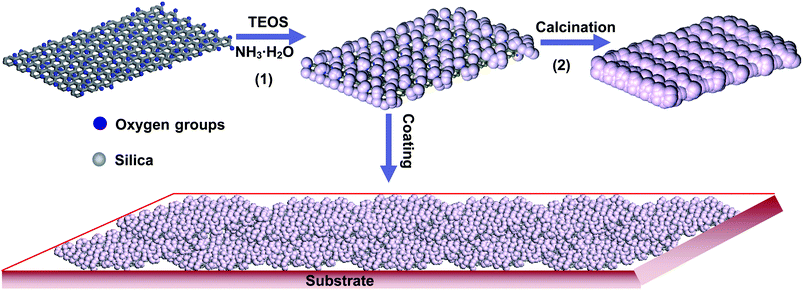 | ||
| Scheme 1 The procedure for the synthesis of GO–SiO2 nanohybrid and its application as precursor of silica sheets and building blocks for superhydrophilic coatings. | ||
Subsequently, the as-synthesized GO–SiO2 was then burned in a muffle furnace at 650 °C for 12 h in order to evaluate the covering effect of silica particles on GO and simultaneously obtain silica nanosheets if possible (process 2). More significantly, the resulting GO–SiO2 hybrid sheets were directly employed as BBs for fabrication of large-area surfaces with the desired wetting properties by the simple drop-coating method.
3.2 Morphology of the GO–SiO2
Morphology observation is the most direct way to judge the attachment effect of nanoparticles on GO sheets. The resulting GO–SiO2 nanohybrids were characterized by atomic force microscopy (AFM), transmission electron microscopy (TEM) and scanning electron microscopy (SEM). A dilute water solution of GO–SiO2 was dropped onto a newly exfoliated surface of mica and then analyzed by AFM. Fig. 1A shows the typical AFM image of pristine GO. We can see that GO nanosheets disperse in water very well with no aggregation and the corresponding height profile shows that the GO nanosheets are ca. 0.8 nm in height, indicating a complete exfoliation of graphite oxide to a single layer. Compared with GO, GO–SiO2 sheets exhibit a dense and uniform coverage of silica nanoparticles on GO surfaces, as shown in Fig. 1B and 1C. The cross-section view illustrates that the average height of GO–SiO2 sheets is ca. 8 nm. Therefore, subtracting the thickness of 0.8 nm for GO sheets, the height of silica nanoparticles is calculated to ca. 3.6 nm, since silica nanoparticles are coated on both sides of GO sheets. Micro-scale individual sheets are observed (Fig. 1B), and a single GO–SiO2 sheet as large as 5 µm in width (Fig. 1C) can be clearly visualized without any touching and overlapping with other sheets, proving the excellent dispersibility of our GO–SiO2 hybrids in water. In addition, such big sheets were evenly and densely coated with uniform nanoparticles without any obvious vacancies, indicating the marvellous loading effect of our one-step “loading from” strategy. In addition, no free silica nanoparticles were found in the blank domains of the mica substrates, confirming the complete separation of free silica by a centrifugal process, if formed. The magnified images for GO–SiO2 (see Fig. 1D and 1E) show unambiguous shape and uniform size of parasitical silica particles. The cross-section view illustrates that the average height of silica is ca. 3.5 nm while the average diameter is ca. 50 nm, which suggests that silica growth is more favored laterally than vertically on the surfaces of GO nanosheets and GO sheets function as an in-solution substrate for particle growth. This phenomenon is analogous to the growth process of dendritic “snowflake-shaped” gold nanostructures on graphene observed by Berry's group.54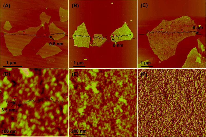 | ||
| Fig. 1 Representative AFM images of GO (A) and GO–SiO2 at different magnifications (B-F) (F is the phase map of E). | ||
The TEM images of GO–SiO2 are shown in Fig. 2A, B. It is consistent with AFM images that the silica nanoparticles coat on GO sheets densely, and the magnified image exhibits a homogeneous size of ca. 50 nm. SEM images of the samples reveal quite conspicuous features about their microstructure and morphology. The samples of GO and GO–SiO2 for SEM measurements were dried in a vacuum oven for a whole night and ground into powder. As shown in Fig. 2C, pristine GO sheets stack tightly to form bulky agglomerates with fairly smooth surfaces and layered structures at the edges. On the contrary, for GO–SiO2 (Fig. 2D), since silica nanoparticles act as spacers to prevent the re-stacking of GO–SiO2 sheets in the drying process, a puffy morphology is observed and we can even see plenty of extremely thin sheets stand individually. Interestingly, some semi-rolled sheets are also found (marked by arrows), suggesting the flexibility of GO–SiO2 hybrids. Based on the special structure, GO–SiO2 powders can be redispersed readily in solvents such as water and ethanol just under mild ultrasonic treatment. Under higher magnification, lots of protuberances with size of ca. 50 nm are observed in the image of GO–SiO2 (Fig. 2E), confirming the existence of silica nanoparticles on the surfaces of GO sheets. Meanwhile, the EDX datum (see Figure S3, S4†) for both TEM and SEM samples confirm the dense coverage of silica for the high percentage of silicon element. In view of their excellent dispersity in a variety of solvents, GO–SiO2 nanohybrids can build a paper material just by vacuum filtration, similar to the preparation of GO paper.55 As shown in Fig. 2F, the side-view of GO–SiO2 paper reveals a regular layered structure through almost the entire lateral section of the paper sample (Note: the corresponding photograph of as-prepared GO–SiO2 paper is presented in Fig. 6C), further verifying the individually dispersed effect for the GO–SiO2 sheets. Otherwise, the regularly layered structure would be impossibly to achieve by such a filtering process for crowded amorphous masses. The GO–SiO2 paper was then reduced by hydrazine vapor at 85 °C,56 and surprisingly, the resulting silica-covered hybrid paper performed good electrical conductivity in the scale of 103–104 S m−1, showing their potential applications in supercapacitors and other electronic devices.
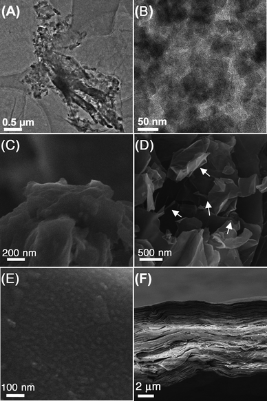 | ||
| Fig. 2 TEM images of GO–SiO2 at different magnifications (A, B); SEM images of GO (C), GO–SiO2 (D, E), and side-view of GO–SiO2 paper (F). | ||
3.3 Tracing the coating process of GO–SiO2
In order to understand the effect of reaction time on the coating result of silica, we traced the reaction process with X-ray diffraction (XRD) and thermogravimetry analysis (TGA) techniques. As shown in Fig. 3A, the peak at 2θ = 10.2° corresponding to the X-ray reflection of the (002) planes of GO57 is weakened step-by-step until it completely vanishes at 24 h. Recent studies have shown that if the regular stacks of graphite oxide or graphite were destroyed by exfoliation, their diffraction peaks would become weak or even disappear.58 So, our XRD data indicates that silica particles grew gradually on the surfaces of GO nanosheets until a full or saturated coating was reached at 24 h when the regular stacks of GO were completely destroyed. Meanwhile, the newly obtuse peak at 23.0° demonstrates that the silica nanoparticles are amorphous.59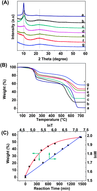 | ||
| Fig. 3 (A) XRD patterns of GO–SiO2 at different reaction stages (a: 0 min, b: 105 min, c: 240 min, d: 420 min, e: 600 min, f: 780 min, g: 1440 min). (B) TGA weight loss curves of GO–SiO2 at different reaction stages (a: 0 min, b: 105 min, c: 240 min, d: 420 min, e: 600 min, f: 780 min, g: 1440 min). (C) The final residual weight of GO–SiO2 as a function of reaction time (red line), and the corresponding natural logarithm of residual weight (lnW) in TGA measurements as a function of natural logarithm of reaction time (lnT). | ||
TGA was performed for the quantitative analysis of silica coated GO. The weight loss curves of GO–SiO2 at different reaction stage are collected in Fig. 3B. Since silica is resistant to high temperature, the powder samples were tested under an air atmosphere in order to burn off all carbon elements whilst retaining the silica. From Fig. 3B, two main weight loss stages are found for the neat GO and GO–SiO2 samples. For the neat GO, the first stage below 250 °C is assigned to the weight loss of labile oxygen-contained groups of GO (∼30 wt%), and the second stage from 500–680 °C is likely attributable to the decomposition of the carbon skeleton of GO.43 The residual weight above 700 °C is less than 3% for GO, clarifying that neat carbon materials can be burned into volatile gases mostly at high temperature. Compared with the neat GO, the GO–SiO2 samples exhibit a lower weight loss at both stages, and the longer the reaction time, the higher the final residual weight, indicating that the silica particles indeed loaded increasingly on GO sheets with time. Accordingly, we made a diagram based on the final weight of GO–SiO2 (that is the weight of loaded silica) at different reaction states, and found that it fitted the function of ExpAssoc
| y = 2.3 + 56.5 × (1 −exp(−x/447)) | (1) |
| lnW = 0.7565 × lnT + 0.1707 | (2) |
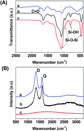
Fig. 4A depicts the FTIR spectra of selected examples. Compared with GO, GO–SiO2 shows two new intensive peaks at 1090 and 465 cm−1, which can be ascribed to the Si–O–Si asymmetric vibration and bending vibration, respectively.60 Furthermore, the peaks at 950 cm−1 are attributed to the Si–OH stretching while the peaks at 800 cm−1 are related to Si–O–Si symmetric vibrations, respectively.44 In order to investigate the chemical composition of the burned GO–SiO2 powder (bGO–SiO2) obtained from the TGA measurements, we also characterized bGO–SiO2 samples by FTIR spectrometry. As shown in Fig. 4A, the disappearance of the peak at 1720 cm−1 related to the C![[double bond, length as m-dash]](https://www.rsc.org/images/entities/char_e001.gif) O vibration of carboxylic groups, indicating the pyrolysis of unstable oxygen-containing groups. In addition, we also functionalized the GO–SiO2 sample with 3-aminopropyltrimethoxysilane (APS) to change the surface properties of GO–SiO2, and the peak of C–Si at 1260 cm−1 in Fig. S1 (see the ESI†) proves the effective attachment of APS and a novel nanosurface with amino groups was obtained, facilitating the next chemical modification.
O vibration of carboxylic groups, indicating the pyrolysis of unstable oxygen-containing groups. In addition, we also functionalized the GO–SiO2 sample with 3-aminopropyltrimethoxysilane (APS) to change the surface properties of GO–SiO2, and the peak of C–Si at 1260 cm−1 in Fig. S1 (see the ESI†) proves the effective attachment of APS and a novel nanosurface with amino groups was obtained, facilitating the next chemical modification.
Raman spectroscopy is always a powerful way to characterize carbon materials, including carbon nanotubes and graphene. Fig. 4B is the typical Raman spectra of GO, GO–SiO2 and bGO–SiO2. For GO, we can see two intensive peaks at 1333 and 1592 cm−1 which refer to the D band, representing a disordered sp3 carbon structure, and the G band resulting from sp2 ordered crystalline graphite-like structures, respectively.61 After coating by silica nanoparticles, the peak position does not shift but the relative intensity of the D and G bands undergoes a considerable transformation. It has been reported that silica, when noncovalently attached to carbon nanotubes, showed no significant band shift or relative intensity variation after the coating process. Therefore, the increase of the D band in GO–SiO2 indicates that the silica nanoparticles were deposited on the surfaces of GO by covalent linkage, indirectly proving the growing mechanism of silica particles on GO described above. In addition, bGO–SiO2 presents no apparent peak in the testing range, and both the D band and G bands vanish completely, providing an even stronger argument that the carbon has been burned off in the process of calcination.
XPS testing was also performed to analyze the chemical composition of GO–SiO2 and the burned product of GO–SiO2 in the course of TGA tests. As shown in Fig. 5A, GO exhibits the C1s peak and O1s peak at 287.67 eV and 533.38 eV, respectively, with a relative C/O atomic ratio of 2.53. After coating of silica by the hydrolysis of TEOS, GO–SiO2 shows expected Si2s and Si2p peaks and the relative contents of C, O and Si are 2.76![[thin space (1/6-em)]](https://www.rsc.org/images/entities/char_2009.gif) :
:![[thin space (1/6-em)]](https://www.rsc.org/images/entities/char_2009.gif) 2.77
2.77![[thin space (1/6-em)]](https://www.rsc.org/images/entities/char_2009.gif) :
:![[thin space (1/6-em)]](https://www.rsc.org/images/entities/char_2009.gif) 1 (see Fig. 5B), which validates the generation of silicon dioxide with atomic ratio of ca. 2. After being burned in air, the carbon content decreased sharply (see Fig. 5C) and the relative contents of C, O and Si are 0.97
1 (see Fig. 5B), which validates the generation of silicon dioxide with atomic ratio of ca. 2. After being burned in air, the carbon content decreased sharply (see Fig. 5C) and the relative contents of C, O and Si are 0.97![[thin space (1/6-em)]](https://www.rsc.org/images/entities/char_2009.gif) :
:![[thin space (1/6-em)]](https://www.rsc.org/images/entities/char_2009.gif) 2.21
2.21![[thin space (1/6-em)]](https://www.rsc.org/images/entities/char_2009.gif) :
:![[thin space (1/6-em)]](https://www.rsc.org/images/entities/char_2009.gif) 1 for bGO–SiO2, demonstrating that carbon element was almost burned off in the course of TGA tests. In addition, APS functionalized GO–SiO2 was also measured by XPS and the nitrogen content of 4.36% demonstrated the successful introduction of amino groups (see Fig. S2†).
1 for bGO–SiO2, demonstrating that carbon element was almost burned off in the course of TGA tests. In addition, APS functionalized GO–SiO2 was also measured by XPS and the nitrogen content of 4.36% demonstrated the successful introduction of amino groups (see Fig. S2†).
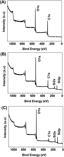 | ||
| Fig. 5 XPS spectra of GO (A), GO–SiO2 (B) and bGO–SiO2 (C). | ||
Furthermore, EDX measurements were done to confirm the XPS results (Figures S4). C, O and Si elements were obviously detected for GO–SiO2 sample, whereas only O and Si element peaks were observed for the bGO–SiO2 sample, ascertaining the expected structures of GO–SiO2 and bGO–SiO2.
3.4 Preparation of silica nanosheets from GO–SiO2
From the AFM and TEM observations as well as the kinetics tracing, we know that GO has been coated with highly dense silica nanoparticles for the product at 24 h. To give further evidence for the sandwich-like structure and explore the potential of such a perfect nanohybrid, we tried to prepare silica sheets by removal of the supporting backbone of GO through calcining GO–SiO2.2D nanomaterials, especially the ultrathin nanosheets, have long been considered attractive materials owing to their unique structures and promising applications. A bottom-up approach was employed by Yang and coworkers for the large-scale production of 2D graphene-based nanosheets which have a sandwich structure consisting of silica, carbon, and metal or metal oxide.62 Distinct from their approach which needs the introduction of a cationic surfactant of cetyltrimethyl ammonium bromide (CTAB), our method just involves the calcination of as-synthesized GO–SiO2 in a muffle furnace at 650 °C for 12 h. The production of silica sheets was confirmed by SEM and AFM measurements. As shown in Fig. 6A, quantities of silica sheets were performed with a few holes in their central planes. In view of their identical dimensions compared with GO–SiO2 sheets, it can be concluded that the silica sheets are just the burning product of GO–SiO2 sheets. Looking back to the characterized morphology of GO–SiO2, it can be speculated that the holes in silica sheets were introduced by the burning of carbon with a relatively discrete coverage of silica nanoparticles at the holed districts, while the large intact area of silica sheets is related to the absolute coating of silica. The AFM image exhibits an analogous sheet-like morphology, and rough surfaces made from nanoparticles are visualized clearly (see Fig. 6B), denoting again the dense coverage of silica nanoparticles on GO for the product of GO–SiO2. Fig. 6C and 6D show the photographs of the black GO–SiO2 paper and the corresponding white silica sheet paper which is obtained by heating GO–SiO2 paper overnight in a muffle furnace, respectively. Even though it was brittle, remarkably, the centimeter-scale silica sheet paper can be clamped tightly with an acutilingual metal tweezer. The silica paper is semitransparent (labeled by a square frame) enabling the naked eye to see the rough background surface. As far as we know, it is the first time free-standing silica paper made of ultrathin silica nanosheets has been obtained; its special properties and applications are to be discovered.
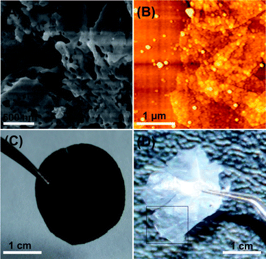 | ||
| Fig. 6 SEM (A) and AFM (B) images of silica sheets obtained by calcining GO–SiO2. Photographs of GO–SiO2 paper (C) and the corresponding silica sheet paper (D) from burned GO–SiO2. | ||
3.5 Application of GO–SiO2 in superhydrophilic coatings
Based on the aforementioned structures and attributes of GO–SiO2 sheets, they are expected to be used as BBs for superhydrophilic coatings. Generally, coatings designed to obtain extreme wetting characteristics can be divided into two branches: superhydrophobic (water droplet contact angle > 150°) and superhydrophilic (water droplet contact angle < 5°) ones.63 Several techniques are known for preparation of superhydrophobic coatings on the surfaces of polymers8 or waxes64 by both physical and chemical treatments to increase the roughness. In the past decade, many reports have been made available on the formation of superhydrophilic coatings of titanium dioxide. In general, TiO2 thin-film coatings can be fabricated by various techniques, including atomic layer deposition,65chemical vapor deposition,66 chemical spray pyrolysis,67electrodeposition,68 and sol–gel dip coating,27etc. However, these techniques can only be applied to refractory substrates (e.g., ceramic, glass, or steel) for high temperature treatment in obtaining crystalline TiO2 (150–750 °C), posing a big limitation for its application as a general coating, especially on organic material substrates, to realize superhydrophilicity. Besides, as mentioned above, these kinds of coatings suffer from a disadvantage that only under UV irradiation they could behave as superhydrophilic film and then return back to the normal phase with a high water contact angle.7 It has been recognized that the best way to achieve a superhydrophilic surface on any substrate is directly, using superhydrophilic coatings or paints. Up to now, however, to achieve such coatings/paints seems an insurmountable challenge. Encouraged by the success of utilizing silica nanoparticles for the construction of superhydrophilic surfaces,19–21 herein we try to exploit the application of our GO–SiO2 sheets as direct BBs for superhydrophilic coatings preliminarily in view of their hierarchical micro–nano structures, excellent dispersity and the ability to form thin film via solution-casting.We choose the distinct materials of ceramic tiles, PP films, and lotus leaves with corresponding hydrophilic, hydrophobic, and superhydrophobic intrinsic characters to represent inorganic, organic, and natural substrates, respectively. We firstly coated GO–SiO2 solution on ceramic tile by distinct means of spin-coating, dip-coating and drop-coating. It has been already demonstrated that a minimum film thickness is required for obtaining superhydrophilic coatings, necessitating multiple deposition cycles.63 In our experiments, the drop-coating method leads to thicker coating and more deposited layers of nanosheets on the surfaces of substrates, contributing to the smaller water contact angle (WCA), so we continued to expand this coating method to fabricate superhydrophilic surfaces on other substrates. The substrates with an area of ca. 10 cm2 before and after GO–SiO2 deposition are shown in Fig. 7A. No matter what substrates were utilized, the building blocks of GO–SiO2 can form a continuous thin film adhered to the substrates tightly. What is more, the primal surfaces topography of substrates is maintained after the coating procedure, essential for coating application. Take lotus leaf and labeled ceramic plate for example, we can still clearly observe the texture of lotus leaf and two labeled parallel grooves after coating GO–SiO2, respectively, indicating the good coating-processability of the GO–SiO2 sheets on flat, crinkled, rough, or smooth surfaces. The wettability of the resultant surfaces was measured in terms of WCA. The WCA of blank substrates and GO coated substrates were also measured to clearly show the superhydrophilic function of GO–SiO2 coatings. We measured each sample at least five times at distinct domains and the final WCA data presented in Fig. 7B are the mean values for five tests (Note: almost the same result was obtained for each measurement). The ceramic tile, wildly used in the building field as a decorative material, is weakly hydrophilic and the WCA is 77.3°. After coating GO, it becomes more hydrophilic and the WCA value goes to 33.9°. Amazingly, the GO–SiO2 coated ceramic tile exhibits a superhydrophilic nature with the water drops spreading out fast and the final WCA tends to 0°, which is extremely significant for ceramic tiles on the outside wall of structures considering their self-cleaning function after a heavy rain. In order to prove the versatility and generality of our GO–SiO2 coatings, we employ subsequently PP film as a representative hydrophobic substrate. The WCA of PP and GO-coated PP is 95.2° and 78.1°, respectively. The coating of GO–SiO2 on PP surface renders it superhydrophilicity with a WCA of ca. 5°. Compared with superhydrophilic PP made by Fang based on electrostatic interactions between the surface functionalized silica nanoparticles and the charged PP substrate,21 our method needs no pretreatment of the PP substrate owing to the remarkable ability to form thin films for GO–SiO2 building blocks on arbitrary substrates. In consideration of our success in constructing superhydrophilic surfaces on both hydrophilic and hydrophobic substrates, we try to realize superhydrophilicity on a superhydrophobic surface represented by the lotus leaf, a widely existing natural plant. As shown in Fig. 7B, the lotus leaf is quite hydrophobic and the corresponding WCA is 152.9°. The GO coatings have shifted it from superhydrophobicity to hydrophilicity with WCA of 40.9°. After coating GO–SiO2, the surface WCA is down to below 5°, a dramatic transformation from the superhydrophobic to superhydrophilic state. Previously, Jiang and co-workers had success in preparing a superhydrophilic carbon film by heating a lotus leaf at high temperature.69 As far as we know, our example is the first time to realize superhydrophilicity on the superhydrophobic surfaces of the lotus leaf without destroying its intrinsic structure, demonstrating the advantage of our nanocoating technology. On the basis of the above results, we can conclude that the GO–SiO2 can be utilized as versatile and general superhydrophilic coatings. The possible mechanism of the superhydrophilicity is discussed below.
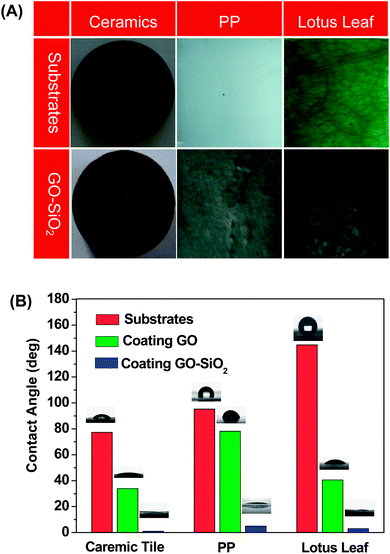 | ||
| Fig. 7 (A) Photographs of blank substrates (top) and GO–SiO2-coated substrates (bottom) of a ceramic tile, PP and a lotus leaf. (B) Water contact angles (WCAs) of blank, GO-coated and GO–SiO2-coated substrates. | ||
It is well known that the wettability of surface is governed by both chemical composition and surface roughness, which can be expressed by the following equation:70
| cosθa = rcosθ | (3) |
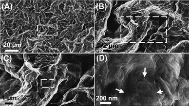 | ||
| Fig. 8 The microscopic morphology of GO–SiO2 coated lotus leaf (the images from B to D are the magnified square areas of the former images and the arrows in D indicate the conspicuous profile of the GO–SiO2 sheet). | ||
4 Conclusions
We have synthesized fine silica nanoparticles-coated graphene oxide nanocomposites via a simple one-step solution approach at room temperature without using any extra templates or surfactants. In our synthetic procedure, an alcohol–water solution was employed as the reaction medium, which is nontoxic and environmental friendly. The as prepared GO–SiO2 hybrid sheets could be made into paper film by a filtering technique, and the film performs at a high conductivity of 103–104 S m−1 after reduction by hydrazine vapor, promising potential applications as catalysts, biosensors, supercapacitors and electrodes for other electronic devices. In addition, the nature of GO–SiO2 can be readily regulated by reacting with silane coupling agents. The GO–SiO2 samples burned in a muffle furnace present plate-like silica, not only demonstrating the dense attachment of silica nanoparticles on the surface of GO but also opening the door for fabricating novel 2D nanomaterials. Furthermore, GO–SiO2 with a hierarchical structure and good dispersity can be employed as a general kind of building blocks to construct large-area superhydrophilic surfaces by the simple coating technique. The wettability of a weakly hydrophilic ceramic tile, hydrophobic PP, and superhydrophobic lotus leaf can be dramatically tuned to superhydrophilic just by coating with a thin film of GO–SiO2.Acknowledgements
This work was financially supported by the National Natural Science Foundation of China (No. 50773038, and No. 20974093), National Basic Research Program of China (973 Program) (No. 2007CB936000), Qianjiang Talent Foundation of Zhejiang Province (2010R10021), the Fundamental Research Funds for the Central Universities (2009QNA4040), and the Foundation for the Author of National Excellent Doctoral Dissertation of China (No. 200527).Notes and references
- A. Nakajima, K. Hashimoto and T. Watanabe, Monatsh. Chem., 2001, 132, 31 CrossRef CAS
.
- Y. Liu, L. Mu, B. H. Liu and J. L. Kong, Chem.–Eur. J., 2005, 11, 2622 CrossRef CAS
.
- I. P. Parkin and R. G. Palgrave, J. Mater. Chem., 2005, 15, 1689 RSC
.
- T. L. Sun, L. Feng, X. F. Gao and L. Jiang, Acc. Chem. Res., 2005, 38, 644 CrossRef CAS
.
- G. B. Crevoisier, P. Fabre, J. M. Corpart and L. Leibler, Science, 1999, 285, 1246 CrossRef
.
- K. Ichimura, S. K. Oh and M. Nakagawa, Science, 2000, 288, 1624 CrossRef CAS
.
- R. Wang, K. Hashimoto, A. Fujishima, M. Chikuni, E. Kojima, A. Kitamura, M. Shimohigoshi and T. Watanabe, Nature, 1997, 388, 431 CrossRef CAS
.
- J. Bico, C. Marzolin and D. Quere, Europhys. Lett., 1999, 47, 220 CrossRef CAS
.
- J. Bico, C. Tordeux and D. Quere, Europhys. Lett., 2001, 55, 214 CrossRef CAS
.
- S. Herminghaus, Europhys. Lett., 2000, 52, 165 CrossRef
.
- S. Heminghaus, Eur. Phys. J. E, 2002, 8, 237 CrossRef CAS
.
- H. Gau, S. Herminghaus, P. Lenz and R. Lipowsky, Science, 1999, 283, 46 CrossRef CAS
.
- S. Minko, M. Müller, M. Motornov, M. Nitschke, K. Grundke and M. Stamm, J. Am. Chem. Soc., 2003, 125, 3896 CrossRef CAS
.
- X. Zhang, F. Shi, X. Yu, H. Liu, Y. Fu, Z. Wang, L. Jiang and X. Li, J. Am. Chem. Soc., 2004, 126, 3064 CrossRef CAS
.
- J. T. Han, D. H. Lee, C. Y. Ryu and K. Cho, J. Am. Chem. Soc., 2004, 126, 4796 CrossRef CAS
.
- J. Wang, Y. Wen, X. Feng, Y. Song and L. Jiang, Macromol. Rapid Commun., 2006, 27, 188 CrossRef CAS
.
- M. Miyauchi, A. Nakajima, K. Hashimoto and T. Watanabe, Adv. Mater., 2000, 12, 1923 CrossRef CAS
.
- H. Irie, W. Washizuka, N. Yoshino and K. Hashimoto, Chem. Commun., 2003, 1298 RSC
.
- X. Liu and J. He, J. Phys. Chem. C, 2009, 113, 148 CrossRef CAS
.
- D. Chen, L. Tan, H. Liu, J. Hu, Y. Li and F. Tang, Langmuir, 2010, 26, 4675 CrossRef CAS
.
- J. Fang, A. Kelarakis, L. Estevez, Y. Wang, R. Rodriguez and E. P. Giannelis, J. Mater. Chem., 2010, 20, 1651 RSC
.
- C. Neinhuis and W. Barthlott, Ann. Bot., 1997, 79, 667 CrossRef
.
- A. Nakajima, A. Fujishima, K. Hashimoto and T. Watanabe, Adv. Mater., 1999, 11, 1365 CrossRef CAS
.
- Y. Zhao, Q. Lu, D. Chen and Y. Wei, J. Mater. Chem., 2006, 16, 4504 RSC
.
- T. Sun, G. Wang, L. Feng, B. Liu, Y. Ma, L. Jiang and D. Zhu, Angew. Chem., Int. Ed., 2004, 43, 357 CrossRef CAS
.
- X. Feng and L. Jiang, Adv. Mater., 2006, 18, 3063 CrossRef CAS
.
- K. Tadanaga, J. Morinaga, A. Matsuda and T. Minami, Chem. Mater., 2000, 12, 590 CrossRef CAS
.
- C. Lee, X. Wei, J. W. Kysar and J. Hone, Science, 2008, 321, 385 CrossRef CAS
.
- A. A. Balandin, S. Ghosh, W. Bao, I. Calizo, D. Teweldebrhan, F. Miao and C. N. Lau, Nano Lett., 2008, 8, 902 CrossRef CAS
.
- K. I. Bolotin, K. J. Sikes, Z. Jiang, M. Klima, G. Fudenberg, J. Hone, P. Kim and H. L. Stormer, Solid State Commun., 2008, 146, 351 CrossRef CAS
.
- M. D. Stoller, S. Park, Y. Zhu, J. An and R. S. Ruoff, Nano Lett., 2008, 8, 3498 CrossRef CAS
.
- G. Goncalves, P. A. A. P. Marques, C. M. Granadeiro, H. I. S. Nogueira, M. K. Singh and J. Gracio, Chem. Mater., 2009, 21, 4796 CrossRef CAS
.
- I. V. Lightcap, T. H. Kosel and P. V. Kamat, Nano Lett., 2010, 10, 577 CrossRef CAS
.
- Y. Si and E. T. Samulski, Chem. Mater., 2008, 20, 6792 CrossRef CAS
.
- S. M. Paek, E. Yoo and I. Honma, Nano Lett., 2009, 9, 72 CrossRef CAS
.
- G. Williams and P. V. Kamat, Langmuir, 2009, 25, 13869 CrossRef CAS
.
- J. Shen, Y. Hu, M. Shi, N. Li, H. Ma and M. Ye, J. Phys. Chem. C, 2010, 114, 1498 CrossRef CAS
.
- G. M. Scheuermann, L. Rumi, P. Steurer, W. Bannwarth and R. Mülhaupt, J. Am. Chem. Soc., 2009, 131, 8262 CrossRef CAS
.
- G. Williams, B. Seger and P. V. Kamat, ACS Nano, 2008, 2, 1487 CrossRef CAS
.
- S. Watcharotone, D. A. Dikin, S. Stankovich, R. Piner, I. Jung, G. H. B. Dommett, G. Evmenenko, S. E. Wu, S. F. Chen, C. P. Liu, S. T. Nguyen and R. S. Ruoff, Nano Lett., 2007, 7, 1888 CrossRef CAS
.
- K. Babooram and R. Narain, ACS Appl. Mater. Interfaces, 2009, 1, 181 CrossRef CAS
.
- M. Bottini, L. Tautz, H. Huynh, E. Monosov, N. Bottini, M. I. Dawson, S. Belluccib and T. Mustelin, Chem. Commun., 2005, 758 RSC
.
- M. Kim, J. Hong, J. Lee, C. K. Hong and S. E. Shim, J. Colloid Interface Sci., 2008, 322, 321 CrossRef CAS
.
- Y. Yang, S. Qiu, W. Cui, Q. Zhao, X. Cheng, R. Kwok, Y. Li, X. Xie and Y. Mai, J. Mater. Sci., 2009, 44, 4539 CrossRef CAS
.
- Q. Fu, C. Lu and J. Liu, Nano Lett., 2002, 2, 329 CrossRef CAS
.
- J. Zhang, Y. Zheng, L. Lan, S. Mo, P. Yu, W. Shi and R. Wang, ACS Nano, 2009, 3, 2185 CrossRef CAS
.
- H. S. Shin, Y. S. Jang, Y. Lee, Y. Jung, S. B. Kim and H. C. Choi, Adv. Mater., 2007, 19, 2873 CrossRef CAS
.
- M. Bottini, A. Magrini, M. I. Dawson, A. Bergamaschi and T. Mustelin, Carbon, 2006, 44, 1301 CrossRef CAS
.
- Y. Liu, C. Zhang, Z. Du, C. Li, Y. Li, H. Li and X. Yang, Carbon, 2008, 46, 1670 CrossRef CAS
.
- Y. Deng, C. Deng, D. Yang, C. Wang, S. Fu and X. Zhang, Chem. Commun., 2005, 5548 RSC
.
- Z. Xu and C. Gao, Macromolecules, 2010, 43, 6716 CrossRef CAS
.
- H. K. He and C. Gao, Chem. Mater., 2010, 22, 5054 CrossRef CAS
.
- L. Zhou, C. Gao, X. Hu and W. Xu, ACS Appl. Mater. Interfaces, 2010, 2, 1211 CrossRef CAS
.
- K. Jasuja and V. Berry, ACS Nano, 2009, 3, 2358 CrossRef CAS
.
- D. A. Dikin, S. Stankovich, E. J. Zimney, R. D. Piner, G. H. B. Dommett, G. Evmenenko, S. T. Nguyen and R. S. Ruoff, Nature, 2007, 448, 457 CrossRef CAS
.
- D. Yang, A. Velamakanni, G. Bozoklu, S. Park, M. Stoller, R. D. Pinea, S. Stankovich, I. Jung, D. A. Field, C. A. Ventrice Jr and R. S. Ruoff, Carbon, 2009, 47, 145 CrossRef CAS
.
- C. Nethravathi and M. Rajamathi, Carbon, 2008, 46, 1994 CrossRef CAS
.
- C. Xu, X. D. Wu, J. W. Zhu and X. Wang, Carbon, 2008, 46, 386 CrossRef CAS
.
- L. Wang, S. Tomura, F. Ohashi, M. Maeda, M. Suzuki and K. Inukai, J. Mater. Chem., 2001, 11, 1465 RSC
.
- M. Prassas, J. L. Phalippou, L. Mench and J. Zarzycki, J. Non-Cryst. Solids, 1982, 48, 79 CrossRef CAS
.
- R. C. Haddon, Acc. Chem. Res., 2002, 35, 997 CrossRef
.
- S. Yang, X. Feng, L. Wang, K. Tang, J. Maier and K. Müllen, Angew. Chem., Int. Ed, 2010, 49, 4795 CAS
.
- F. C. Cebeci, Z. Wu, L. Zhai, R. E. Cohen and M. F. Rubner, Langmuir, 2006, 22, 2856 CrossRef CAS
.
- S. Shibuichi, T. Onda, N. Satoh and K. Tsujii, J. Phys. Chem., 1996, 100, 19512 CrossRef CAS
.
- J. Aarik, A. Aidla, T. Uustare, M. Ritala and M. Leskela, Appl. Surf. Sci., 2000, 161, 385 CrossRef CAS
.
- V. G. Bessergenev, R. J. F. Pereira, M. C. Mateus, I. V. Khmelinskii, D. A. Vasconcelos, R. Nicula, E. Burkel, A. M. Botelho do Rego and A. I. Saprykin, Thin Solid Films, 2006, 503, 29 CrossRef CAS
.
- A. Conde-Gallardo, M. Guerrero, N. Castillo, A. B. Soto, R. Fragoso and J. G. Cabanas-Moreno, Thin Solid Films, 2005, 473, 68 CrossRef CAS
.
- S. Karuppuchamy, J. M. Jeong, D. P. Amalnerkar and H. Minoura, Vacuum, 2006, 80, 494 CrossRef CAS
.
- S. Wang, Y. Zhu, F. Xia, J. Xi, N. Wang, L. Feng and L. Jiang, Carbon, 2006, 44, 1845 CrossRef CAS
.
- R. N. Wenzel, Ind. Eng. Chem., 1936, 28, 988 CrossRef CAS
.
- X. Liu and J. He, J. Colloid Interface Sci., 2007, 314, 341 CrossRef CAS
.
- D. Lee, M. F. Rubner and R. E. Cohen, Nano Lett., 2006, 6, 2305 CrossRef CAS
.
Footnote |
| † Electronic supplementary information (ESI) available: FTIR spectra and XPS pattern of GO–SiO2–NH2, EDX spectra of GO–SiO2 from TEM and SEM measurements. See DOI: 10.1039/c0nr00609b |
| This journal is © The Royal Society of Chemistry 2011 |

