Quantitative high-resolution sensing of DNA hybridization using magnetic tweezers with evanescent illumination†
Piercen M.
Oliver
,
Jin Seon
Park
and
Dmitri
Vezenov
*
Lehigh University, Department of Chemistry, 6 E. Packer Ave, Bethlehem, PA 18015, USA. E-mail: dvezenov@lehigh.edu
First published on 19th November 2010
Abstract
We applied the combined approach of evanescent nanometry and force spectroscopy using magnetic tweezers to quantify the degree of hybridization of a single synthetic single-stranded DNA oligomer to a resolution approaching a single-base. In this setup, the 200 nucleotide long DNA was covalently attached to the surface of an optically transparent solid support at one end and to the surface of a superparamagnetic fluorescent microsphere (force probe) at the other end. The force was applied to the probes using an electromagnet. The end-to-end molecular distance (i.e. out-of-image-plane position of the force probe) was determined from the intensity of the probe fluorescence image observed with total-internal reflectance microscopy. An equation of state for single stranded DNA molecules under tension (extensible freely jointed chain) was used to derive the penetration depth of the evanescent field and to calibrate the magnetic properties of the force probes. The parameters of the magnetic response of the force probes obtained from the equation of state remained constant when changing the penetration depth, indicating a robust calibration procedure. The results of such a calibration were also confirmed using independently measured probe-surface distances for probes mounted onto cantilevers of an atomic force microscope. Upon hybridization of the complementary 50 nucleotide-long oligomer to the surface-bound 200-mer, the changes in the force–distance curves were consistent with the quantitative conversion of 25% of the original single-stranded DNA to its double-stranded form, which was modeled as an elastic rod. The method presented here for quantifying the hybridization state of the single DNA molecules has potential for determining the degree of hybridization of individual molecules in a single molecule array with high accuracy.
Introduction
Detection of DNA hybridization is at the heart of many recently developed technologies for bioanalysis, especially for use in genome sequencing. Methods that aim to achieve single-molecule resolution are of particular interest due to their promise of high speed analysis and low cost. Approaches for detecting single-molecule hybridization range from fluorescence correlation spectroscopy (FCS) of fluorophores,1,2 molecular beacons3 and nanoparticle probes,4 to conventional fluorescence microscopy, usually with total internal reflection fluorescence (TIRF).5,6 The basic tenets are the same for each method—a complement for a target DNA strand attached to a surface is introduced into solution and the resulting ‘binding’ or ‘no-binding’ event is viewed optically. Although most researchers employ a fluorescent label on both the target and probe strands, methods for a label on the target strand only have also been developed.7 All such techniques have the advantage that no amplification of the DNA is required and a large number of binding events can be captured in parallel. For these reasons, single-molecule DNA hybridization has been employed heavily in the development of next-generation sequencing technologies.8,9 Previous work demonstrated use of the evanescent field scattering by micron-sized probes for label-free detection of hybridization in small DNA strands.10 Our work builds on this technique by quantifying the degree of hybridization in an individual strand through the application of force. The method presented in this paper uses single-molecules, is label-free, and, in principle, does not require a high magnification objective.Single molecule force spectroscopy (SMFS) has been used extensively for determining the nature of specific and non-specific interactions of biological molecules with surfaces or other biomolecules. The capability to measure the elastic properties of short polymers in an array format is important for the development of high throughput SMFS. Atomic force microscopy (AFM) and optical tweezers are the most widely employed force spectroscopy techniques and have enabled single molecule studies of stretching biological polymers and inter/intramolecular binding, including protein unfolding,11,12DNA/DNA and DNA/protein interactions,13,14 conformational changes in polysaccharides,15 mechanochemistry of single-bonds,16 and peeling of single DNA oligomers from solid surfaces.17 Despite their extensive use in force spectroscopy of biomolecules, optical tweezers and AFM are not readily amenable to implementation in a parallel format, since a different optical trap or AFM tip is needed for each polymer in the array. On the other hand, magnetic tweezers provide the means for parallel acquisition of molecular force-extension curves through measurement of the out-of-plane (z) position of multiple magnetic probes all undergoing simultaneous displacement under an applied external magnetic field.18–22 The technique allows for the capture of numerous force-extension curves of single polymer molecules within a field-of-view of an optical microscope. We are particularly interested in chip-based SMFS for DNA molecules, since our goal is to develop a platform capable of high-resolution measurements on short DNA oligomers. Advances in the introduction of chemical functional groups to synthetic and genomic DNA23 make it possible to use robust covalent attachment of DNA for prolonged, multi-cycle force spectroscopy on a massively parallel scale. With single nucleotide resolution, application of force spectroscopy to rapid genome sequencing can be envisioned.24
In this paper, we used high-resolution single molecule force spectroscopy based on magnetic tweezers with evanescent illumination (evanescent nanometry), also recently implemented by Liu et al.25 This technique has several practical advancements in terms of improved force and molecular extension sensitivity, low noise, and facile force calibration of each magnetic probe-biomolecule pair. Probe microspheres are synthesized in-house to optimize specific surface chemistry, reduce the surface roughness for uninhibited attachment of a single molecule, and maximize the dynamic range (i.e. fluorescent signal and magnetic force).
Experimental design
The z-position of a magnetic probe is normally found using analysis of Airy-ring profiles.20,26 Such analysis can be done on several molecules in parallel,27 although the method benefits from specially fabricated probes with improved diffraction efficiency to achieve sub-nm resolution.26 We chose evanescent nanometry, because it does not require imaging of the probes with high lateral resolution and, in principle, can be implemented with low magnification objectives and only a few pixels dedicated to each molecule-probe pair. The method is inherently differential by nature (measures difference in position of the bead with respect to the solution-solid interface), thus, negating adverse drift effects for short acquisition times. The disadvantage of this approach is that knowledge of an accurate penetration depth can be difficult to obtain, since the penetration depth for large microspheres is expected to deviate from the unperturbed theory of point emitters.28 This drawback is not critical (i.e. the absolute molecular extension is not needed) in situations where relative changes in the state of the biomolecules are relevant; in particular, we are interested in bioanalytical applications of magnetic tweezers, such as detection of biomolecular binding, changes in conformation or secondary structure.In any magnetic tweezers experiment, the inhomogeneity of the probes presents a problem for force calibration. Even for the most controlled probe synthesis, variations in magnetite content and diameter are expected. Hence, force calibration must be performed for each probe. Conventionally, one performs force calibration of magnetic tweezers using the equipartition theorem (or a fit to a full power spectrum of a probe's fluctuations). A probe's position z-variance 〈σ2z〉 can be used to derive the polymer rigidity (dF/dz), in order to get the probe force at a given electromagnet current:
 | (1) |
In this paper, we show that the freely jointed chain model for ssDNA stretching can accommodate several fitting parameters including parameters for probe force and information about the evanescent penetration depth. The simple model yielded consistent forces for any one probe and penetration depths consistent with independent calibration using a combined AFM/TIRF instrument. Using our experimental setup of electromagnetic tweezers with evanescent wave excitation, we are able to acquire stretching curves for individual molecules of ssDNA and detect hybridization at a resolution approaching a single nucleotide with the future goal of highly-parallel measurements.
A magnetic tweezers instrument that achieves observation of multiple probes, while simultaneously applying force using an electromagnet positioned above the sample, is most easily implemented using an objective-style TIRF microscope to create an illuminating evanescent field. Fig. 1 shows a schematic of the placement of the electromagnet, fluid cell with the sample, and TIRF objective in such a system. In spite of a typically greater force achieved by permanent magnets over electromagnets, we opted to use a stationary electromagnet, because re-positioning of the magnet during the experiment is not required, thus, eliminating noise due to mechanical movement of the positioning stage in the course of a force ramp. Relatively high fields (>0.1 Tesla) can still be achieved with the electromagnet (Fig. 2). The force ramp is easy to implement via a coil current ramp. Hysteresis of the magnetic field is negligible at the loading rates used in our experiments (see section S1 in the Electronic Supplementary Information, ESI†). The change in the incident angle θ of the laser beam enables selection of the penetration depth of the evanescent field.
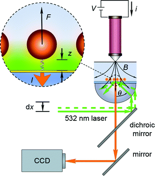 | ||
| Fig. 1 Experimental setup for magnetic tweezers force spectroscopy with evanescent illumination. The sample is illuminated by a 532 nm laser beam through a high numerical aperture lens (NA = 1.45). The lateral position dx of the optical fiber from the laser source is adjusted with a motorized actuator and changes the position of the focused spot in the back-focal plane of the objective. The control of the laser spot position allows for adjustment of the laser angle θ incident to the glass/water interface. A thin layer (∼12.5 nm) of gold (yellow) is present at the interface for reaction with thiolated DNA. The evanescent field propagates from the glass/water interface to illuminate the tethered magnetic-fluorescent probes (inset). Force F is applied to the probes by an electromagnet placed above the fluid cell. The magnetic field B is modulated by a current i through the coil of the electromagnet. Fluorescent emission from the probesI is filtered from the incident laser radiation by a dichroic mirror and a high pass filter and detected by a digital camera connected to a computer. | ||
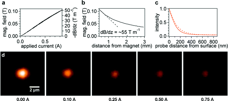 | ||
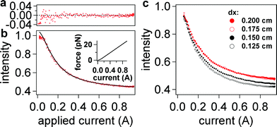
| Fig. 2 (a) Linear response of electromagnetic field and field gradient with applied current at a distance of 0.5 mm. (b) Magnetic field versus distance at 0.94 A applied current. The magnetic field gradient (dashed line) at a distance of 0.5 mm from the bead is ∼55 T m−1. (c) Probe fluorescent intensities as a function of distance at two actuator positions 0.150 cm (solid) and 0.200 cm (dashed). (d) Colorized probe image versus electromagnet current for stretching 200-mer ssDNA. Upon applying force to the probes, we observe a noticeable change in intensity, which depends non-linearly on the current applied to the electromagnet. | ||
Angle positioning can be readily achieved by altering the lateral displacement dx of the single-mode optical fiber connected to the laser source (λ = 532 nm). The setup provides essentially hands-free remote operation, being fully computer controlled except for the lateral stage positioning.
Experimental details
Sample surface preparation
Fig. 3 shows a schematic diagram of how DNA was covalently attached to the surface of the gold-coated coverslip and how force probes were then covalently bound to the DNA. Transparent gold-coated coverslips were prepared by e-beam deposition of 1.5 nm Ti, and 12 nm Au on piranha-cleaned 24 mm × 60 mm coverslips (VWR Superslips No. 1.5). The coated coverslips had a transmission of ∼20% for 532 nm light measured by a UV-Vis spectrometer. Prior to surface modification, the gold-coated coverslip was cleaned by nitrogen-oxygen plasma (Harrick Plasma, Ithaca, NY) on a high power setting for 1 min, rinsed with ethanol and dried with a stream of filtered nitrogen. Our ssDNA oligomer was 200 base pairs long (0.116 μm) and was purchased with 3′-thiol and 5′-amine end modifications (5′-NH2-(CH2)6-TTTTTTTTTTTTTTTTACGCACCAATCCGA GACATTTGTCATACTTGTGGCTGAGTTGCAACGCTGTAATTAATCCCGCATTCTACGCGCAGGCATGGAGCTGATGGAAAGAGTTCACCCTTAGCATTCGTGTACCGTGTGTTTGAGCATTTAGTCCCTACTTATAACGTGGCATTTGTGGAGGATTTTTTTTTTTTTTT-(CH2)3-SH-3′) (Biosynthesis, Lewisville, TX, USA). The sequence was constructed in order to eliminate as much secondary structure as possible by randomly generating sequences with certain limitations. Namely, no repeats of any particular base more than three times in a row were allowed and no more than a five-base sequence could repeat beyond seven bases from any one particular position. Any disulfides present were deprotected in 1 M NaCl PBS containing 5 mM tris-carboxyethyl phosphine (TCEP, Alfa Aesar) for 1h. 20 μL of the ssDNA solution was pipetted on the coated coverslip and placed in a humid chamber at room temperature for 1 h. The sample was rinsed with deionized water, incubated in a solution of 1 M NaCl PBS, exchanged three times every 15 min, and finally rinsed with deionized water. The surface was passivated with a solution of 3 mM 6-mercaptohexanoic acid (MHA) (Sigma Aldrich) in 1 M NaCl PBS overnight, rinsed in the same fashion, and dried with nitrogen.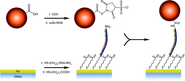 | ||
| Fig. 3 Reaction scheme of probe and DNA attachment to gold-coated glass coverslip. | ||
Fluid cells were constructed by placing a thin ring of 5-minute epoxy (Devcon 5 min Fast Drying Epoxy, Riviera Beach, FL) around the edges of the sample to adhere a 100 μm-thick mylar film with punched inlet and outlet holes. The chamber dimensions were approximately 45 mm × 10 mm × 0.2 mm. Blunt-ended needles (23 gauge, Henkel Loctite) were glued with 5-minute epoxy around the inlet and outlet holes for infusion of rinse buffer and activated magnetic force probes.
Attachment of magnetic-fluorescent probes
Microspheres were prepared by emulsification of polymer solutions that contained 10 nm diameter magnetite nanoparticles (>5% v/v of total) and rhodamine 6G organic dye (experimental detail on fabrication of the force probes will be provided elsewhere). Smooth probes of low polydispersity were synthesized with a diameter of 4.5 μm (FWHM of ±12%, confirmed by scanning electron microscopy (SEM), see section S2 in ESI†). The superparamagnetic response of these beads was verified by a vibrational sample magnetometer (VSM) (ESI, Fig. S3†). Using 532 nm excitation, we observed good fluorescent response of these probes with low photobleaching on the time scales of our experiments (<1 min).For attachment to ssDNA oligomers, the beads from 25 μL of a solution of synthesized force probes (1–2% solids) were washed three times with 1 mL of pH 5.4 100 mM MES (2-(N-morpholino)ethanesulfonic acid, MP Biomedicals) buffer with centrifugation and resuspended in the same buffer. 10 mg of 1-ethyl-3-(3-dimethylaminopropyl)carbodiimide (EDC) and N-hydroxysulfosuccinimide (sulfo-NHS) were added and left standing for 1 h. The probes were washed 3 times with 1 mL pH 8.0 PBS buffer (10 mM with 150 mM NaCl) and resuspended in 0.5 mL pH 8.0 PBS buffer containing 0.1% Tween20 (Calbiochem). A solution of activated probes was infused in the fluid cell after an initial flush with pH 8.0 PBS 0.1% Tween20 and incubated for 1.5 h. Unbound beads were then removed from the surface by slowly infusing the same buffer. Further addition of 100 nM 50-mer reverse-complement centered on the 200-mer strand (Integrated DNA Technologies, Coralville, IA, USA) was conducted in a similar fashion.
Electromagnet design
The electromagnet was designed to maximize the z-field gradient while maintaining minimal x-y gradients to avoid lateral movement of the probes. A high-permeability mumetal core (Mμshield, Londonberry, NH, USA) (0.5′′ diameter, 60.3 mm in length) was tapered at an angle of 45° from one end and terminated in a round tip of radius 1.5 mm. According to numerical simulations reported elsewhere,29 a magnet with a tip radius of 1 to 1.5 mm provides the highest fields considering the thickness of our flow cell. Using 30-gauge copper coiling wire, 1359 turns were laid in 7 layers giving a resistance of 24.6 Ω. The low currents (<1 A) used in our experiments made active liquid cooling unnecessary, while still maintaining a high magnetic field gradient.The electromagnet was powered by a linear 24 V DC power supply modulated by a proportional power module (PWM950, Magnetic Sensor Systems, Van Nuys, CA, USA) through a 0 to 5 V input from a multifunctional USB I/O board (NI USB-6215, National Instruments). Control of the I/O board was enabled by a NIDAQ Tools XOP using custom code written in Igor Pro 6.1 (Wavemetrics, Inc.). Field measurements were made using a Hall effect sensor (Allegro Microsystems, Worcester, MA, USA) while moving the electromagnet on a motorized stage. The electromagnet displays a linear dependence on applied current and fields of just over 0.1 Tesla at close distances (Fig. 2a & b). On average, the electromagnet tip was about 0.5 mm above the probes during our experiments with a field gradient of ∼55 T m−1.
Evanescent illumination and detection
An objective-type TIRF system was assembled using an Olympus IX71 inverted optical microscope with a high numerical aperture TIRF lens (Olympus, 60x, NA = 1.45) and a 532 nm 12 mW laser (OZ-Optics, Ottawa, Ontario, Canada). The refractive indices for water (nwater = 1.333) and glass coverslip (nglass = 1.519) gave a critical angle of θc = 61.1°. The laser beam was TM polarized, with a final power set at ∼4 mW at the input (the microscope optics attenuated the input power by approximately 90%). A motorized actuator (CMA-12CCCL, Newport) changed the incident laser beam angle to allow for control of the penetration depth of the evanescent field. The quantity dx was referenced to the lateral position of the marginal ray in our setup (i.e. the highest incident angle). Beads were imaged by an iXon DV888 (Andor Technologies, Belfast, Ireland) back-illuminated electron-multiplying charge-coupled device (EMCCD) camera (0.227 μm per pixel, >95% quantum efficiency at 532 nm) cooled to −85 °C. Custom written Igor Pro code with an XOP allowing communication between the camera and computer (Bruxton, Seattle, WA, USA) enabled movies to be taken and streamed to disk at frame rates of up to 30 Hz depending on the exposure time and size of the region of interest (ROI). An active response vibration isolation platform (StableTable, Herzan, Laguna Hills, CA, USA) stabilized the entire setup.Evanescent field penetration depths d were later determined from a simultaneous AFM and TIRF experiment. A probe was glued to an AFM cantilever and immersed in pH 8.0 PBS 0.1% Tween20 above a gold-coated coverslip. The bead was moved from contact to 1 μm away from the surface while capturing a movie. Data at several angles, or actuator positions, were taken (Fig. 2c). The data were fit to exponentials and d was found as a function of incident angle (see section S3 in ESI for details†).
Data capture and analysis
In a typical TIRF/magnetic tweezers experiment, we found “active” probes, or probes that display proper extension behavior, by linearly ramping the current between zero and maximum at a rate of 0.5 Hz while previewing the sample. A smaller capture area was created around those probes that were blinking or “active” (see Fig. 2d). In a single field of view (144 μm × 144 μm) we found on average 1 to 2 active probes (upwards of 36 probes viewed simultaneously has been reported elsewhere,27 but such a high number appears to be rare in literature). The total number of beads and percentage of active beads appeared to be affected significantly by both specific and blocking chemistry used, which was not the objective of this research and was not optimized. Exposure time and laser intensity were tuned to maximize the bead intensity without saturating the detector (typical settings were 0.02 to 0.10 s exposure time and ∼25% of the maximum laser power or ∼4 mW). A sinusoidal current modulation was applied to the electromagnet at a rate of 0.1–0.2 Hz during movie capture. We chose sinusoidal modulation to avoid problems with magnetic induction that could be caused by sharp changes in current with a saw-tooth pattern. Data analysis to generate intensity-current curves was performed using custom Igor code. Initial probe locations were found by thresholding and then (more accurately) from a fit to a 2-D Gaussian function. Intensities were then computed by first subtracting a plane-fit background (from a 2 μm-wide ROI surrounding the region of integration of the probe image) and then numerically integrating in the x and y directions over a circular region with a diameter of 18 μm around the center of the probe for each frame. The x–y fluctuations were determined by fitting a 2-D Gaussian function to the probe image at each frame in order to confirm a uniform distribution (corresponding to a single tether attachment). Instrumental noise was approximately 0.5 nm and 5 nm for the out-of-plane and in-plane bead displacements, respectively (see section S4 in ESI†). Beads displaying asymmetric lateral fluctuations were assumed to have multiple tethers and excluded from analysis.Results and discussion
Our initial results indicated that a very stable system suitable for pico-Newton single molecule force spectroscopy had been developed. Fig. 4 shows the raw intensity of a single probe during several subsequent extensions and retractions of ssDNA over a period of 25 s. The intensity data clearly indicates excellent reproducibility, low noise, and low photobleaching. All data captured on active beads followed this same trend (see section 5 in ESI† for examples from several other beads in the same experiment). Each “force curve” is plotted as normalized intensity (with respect to the maximum intensity observed) versus applied current in order to perform side-by-side comparison of different retraction rates (Fig. 4c) or different penetration depths (actuator positions) (Fig. 5). As the electromagnet current is ramped, the magnetic force applied on the bead increases and stretches the DNA molecule. The changes in the distance of the bead from the surface manifest themselves as changes in intensity of the bead image (i.e. a lower intensity indicates a greater distance, see Fig. 2). We observed hysteresis between extension and retraction of DNA for the intensity-current curves, which we attribute to either molecule–surface interaction or non-equilibrium stretching of the possible secondary structure of the ssDNA (e.g. due to base stacking or pairing—the sequence of our model DNA does not preclude loops due to formation of 5-bp or 6-bp-long double-stranded regions). Magnetic field measurements of our electromagnet confirmed that induction hysteresis is not a factor (<1% contribution) in observed differences (see section S1 in ESI†), although it does limit the rate of force curve acquisition to below 0.2 Hz. A comparison of intensity-current loops conducted at different rates indicates that extension (blue curves) at higher rates yields greater hysteresis, yet all retraction curves (red) align without a dependence on rate. Hence, we chose to use the retraction curves in our analysis to avoid the complexity of interpretation of the effect of secondary structure (unfolding of marginally stable hairpins) or pinning on the stretching curves (further analysis indicates a reduction in contour length of approximately 30 single-stranded bases for the extension, see section S6 in ESI†). The intensity-current data are further averaged over the period of the captured video (typically, ∼2 min or four curves) and provided a starting point for our analysis for a given set of experimental parameters (incident angle, rate, bead, etc.). All subsequent intensity-current data refer to an averaged retraction trace unless otherwise indicated.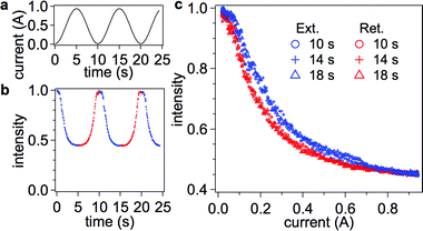 | ||
| Fig. 4 Applied electromagnet current (a) and raw probe intensity data (normalized to the intensity at i = 0 Amps) (b) versus time. Extension of DNA is indicated in blue and retraction in red. Intensity as a function of applied current is shown in (c). Three force loops are shown at different cycle times. Reducing the cycle time to 10 s introduces no hysteresis in the intensity-current retraction curves. There is, however, a hysteresis between the retraction and extension curves in all three cycle times. The hysteresis does not disappear until approximately 0.7 A of current is reached when the extension curve shifts to overlap the retraction data. | ||
 | ||
| Fig. 5 Intensity-current data from retraction measurements fitted to eqn (6) in the text. (a) Plot of residuals for two intensity-current curves (raw data) indicating a noise level of less than 2% over all fits at high forces (i > 0.1 A). (b) The raw data (red) for two retraction curves; the black line is a fit from averaged data (not shown). Aside from normalization of each curve to its maximum intensity, no further modification was performed to align the data. Inset: expected variation of force with current based on eqn (4) and experimental data for magnetic field shown in Fig. 2a and 2b. (c) Averaged retraction data for four different dx laser positions (corresponding to different penetration depths). For clarity, the normalization in (c) is based on the fits to eqn (4), resulting in an Io value corresponding to the position of the surface (i.e. a value of I = 1 corresponds to z = 0 nm). Four retraction intensity-current curves were averaged for each laser position dx and then fitted to eqn (5). The standard deviation at each point is smaller than the size of the markers (<1% of the actual intensity value). Fitting results from this data set and others are listed in Table 1. | ||
Interpretation of intensity versus applied current curves
Raw data obtained with our instrument provides force curve data in the form of intensity of the image of the fluorescent bead versus current applied to the electromagnet. An equation to fit molecular and instrumental parameters to these data can be constructed from (i) the dependence of bead image intensity on distance from the interface for an evanescent field, (ii) the relationship between applied current and force, and (iii) the model for single molecule stretching of ssDNA.An evanescent wave propagates into a medium with an exponential decay. Our numerical simulations of the fluorescent image of a microsphere excited by an evanescent wave show that the total intensity of the fluorescence also exhibits exponential decay with distance from the surface when captured with high NA objectives.28 Empirically observed z dependence (Fig. 2c) bears out this expected behavior of total image intensity in the range of interest (see section S3 in ESI†). Therefore, the probe distance from the surface z is a function of the measured intensity I, the maximum intensity I0 at contact, and the penetration depth d of the evanescent field:
 | (2) |
Typically, penetration depths can range between 70 nm and 200 nm or more, depending on the incident angle and refractive indices of materials at the interface. The exponential dependence of intensity on the probe position makes evanescent nanometry an ideal technique for measuring small extensions, especially since the penetration depths are on the order of the length of short (<500 bases) DNA oligomers and many proteins. Since the reference for z-displacement of the probe is the sample surface, and not other immobilized beads, a simple measure of the total intensity is all that is required to locate its out-of-plane z position. To measure the molecular extensions by evanescent nanometry, a calibration must be performed at the start of any experiment to determine the penetration depth of the field. We demonstrate that by fitting raw data to a known response of the macromolecule under tension (e.g. modeled as a freely-joined polymer) the ratio of the molecular contour length and penetration depth can be obtained as one such calibration. The method is only an absolute measure of the molecular extension if the contour length of the molecule (or part of the molecule) is known. Therefore, it will primarily be useful for applications where the change in the state of the molecule is of main interest.
Typical force calibration of optical or magnetic tweezers involves measurements of x, y or z-fluctuations for use in the equipartition theorem to determine the stiffness of the confining potential. The analysis of fluctuations, however, is problematic with pixel array (e.g.CCD) sensors, since one would have to correct for blurring effects (see section S6 in ESI†), if the exposure time is long compared to the system relaxation time (friction coefficient/stiffness ratio is 50–200 μs for our system). The exposure-time correction depends on the elasticity of the tether,29 complicating the analysis, since our exposure times are always kept at greater than 0.5 ms due to limits in signal-to-noise ratio in our system. We estimate that, using the fluctuation method, the forces in our system can be as much as a factor of 2–3 off even at very short exposure times (<100 μs) that still have reasonable signal to noise ratio (see section S6 in ESI†). In the case of evanescent nanometry, a photodiode detector would be the most straightforward high bandwidth solution for obtaining force information from z-fluctuations of a probe, but a more complex sensor, such as a CCD camera, is required for parallel analysis of multiple probes in a single field of view. Since our goal is to develop approaches to SMFS in an array format, we focus on the use of slow imaging sensors that have potential for future rapid acquisition of numerous force curves in parallel.
We observed that the relationship between applied electromagnet current i and magnetic force F is linear at forces above around 2–3 pN, whereas below 2–3 pN, we are in a non-saturating region. The full range of forces is described by the Langevin function, ![[script L]](https://www.rsc.org/images/entities/char_e144.gif) :
:
 | (3a) |
 | (3b) |
In eqn (3), Vbead is the volume of a single bead, ρbead and ρm are the densities of the bead and magnetite, respectively, MD is the domain magnetization of magnetite (4.46 × 10⁵ A m−1), B is the magnetic field, and DNP is the diameter of the magnetite nanoparticles (∼10 nm). Since both B and ∇B are directly proportional to coil current i (see Fig. 2a), we can express changes in magnetic force with applied current by using a force sensitivity factor encompassing all of the constants from eqn (3):
| F(i,SF,i0) = SF·(i/i0)·i | (4) |
A widely accepted model to describe ssDNA stretching is the freely-jointed chain (FJC) model with finite segment elasticity:30–33
 | (5) |
 | (6) |
Due to an excluded volume effect (i.e. the spatial constraints of having two barriers—probe and surface—at opposite ends of the single-stranded DNA), a non-zero elongation at zero applied magnetic force is expected in our molecule-bead system. In addition, scaling predictions indicate deviation from simple polymer models in a low force regime.34 Therefore, at very low forces, the FJC model is not an adequate representation of the DNA tether and we fit our data only at a high stretching force regime (>1 pN). Our experimental results indicate that the bead intensity evens off at low applied force (or at an applied current of less than ∼0.04 A), meaning, along with the above considerations of subtleties of low force regime, that the crude normalization based on the maximum experimental intensity is not the quantity I0 from eqn (2). Instead, the value of I0 needs to be a fitting parameter, along with the force parameters, SF and i0, and the penetration depth d.
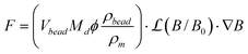
Fig. 5a shows an example of the fit applied to the data values in the range of 0.1 A to 0.94 A of current. The fit follows the functional form of eqn (5) well, as evidenced by the low residuals, which are (mostly) uniformly distributed around zero. Four intensity-current curves (from one movie sequence) were fitted for each of the four penetration depths captured on one probe (Fig. 5c). The results from fits to these magnetic tweezers intensity-current curves are summarized in Table 1.
| dx/cm | L max ss /d | d/nm (Lmaxss = 116 nm) | S F/pN A−1 | I 0 |
|---|---|---|---|---|
| a The error indicated is the standard deviation of the fit coefficient. | ||||
| 0.125 | 0.992 ± 0.003 | 117.0 ± 0.3 | 25.4 ± 0.3 | 1.088 ± 0.003 |
| 0.150 | 0.907 ± 0.002 | 127.9 ± 0.3 | 25.8 ± 0.3 | 1.021 ± 0.003 |
| 0.175 | 0.836 ± 0.003 | 138.7 ± 0.5 | 24.2 ± 0.3 | 1.042 ± 0.003 |
| 0.200 | 0.834 ± 0.002 | 139.0 ± 0.3 | 24.0 ± 0.2 | 1.048 ± 0.002 |
Interpretation of ssDNA force-curve fitting
Fitting to the force curve in Fig. 5b yielded a proportionality constant of i0 = 28.6 ± 0.4 mA, which is very near the expected value of 29.4 mA calculated at an electromagnet distance of 0.5 mm from the probe (assuming 10 nm magnetite nanoparticles, see eqn (3b)). A small deviation of i0 from the calculated value is expected, because neither the actual distance of the electromagnet from the probe nor diameter of magnetite nanoparticles are precisely known. In fact, when fixing different values of i0, we found that small changes (within a factor of 2) did not alter (within 10%) the values of SF and d derived from the fits or the quality of the fit. All of the data in Table 1 were then found by setting i0 = 28.6 mA, since no realignment was done during the experiment.The fitting function yields a ratio of contour length to penetration depth. Thus, one quantity must be known in order to get the value of the other. In this case, we used a known synthetic sequence (200 bases in length) and well-defined covalent attachment chemistry, so we were able to set the contour length to Lmaxss = 116 nm and obtain the values of penetration depth listed in Table 1. Any deviation of the contour length from its true value, due to pinning (i.e. changes in the point of attachment) or robust secondary structure, would alter the calculated penetration depth, although the results after addition of a complementary strand, discussed later, help corroborate this value of Lmaxss. In our case, the penetration depth values are within the expected range of those calculated from AFM/TIRF data (Fig. 6) and different by only a few nm for each dx setting. These deviations are expected, because a different sample, probe, and flow cell setup was used for AFM experiments, thus introducing possible slight changes in alignment (ESI, Fig. S5†).
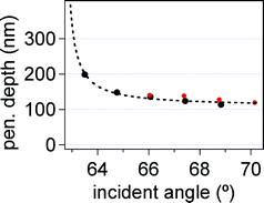 | ||
| Fig. 6 Penetration depth versus incident angle calculated independently from AFM/TIRF data (black) and fits to eqn (6) (red). Dashed black line is a guide to the eye through TIRF/AFM results for d. | ||
An important result seen in Table 1 is the constancy of SF across different penetration depths. Although the penetration depths change, which corresponds to a change in dynamic range of our setup, SF is found precisely within less than 2 pN A−1 purely from fitting raw data to eqn (5). Thus, SF is truly independent of the penetration depth and precise knowledge of d for the analysis is not required (although knowledge of appropriate equation of state is required). Furthermore, a value of 10–30 pN A−1 is within the expected range of force values from probe magnetite loading and magnetic field measurements (ESI, Fig. S3†). The error in determination of d is around 0.3 nm, implying that we should be able to achieve the resolution of a single nucleotide (0.58 nm) in the length of the DNA molecule.
The low fit residuals give further justification for the use of a linear force sensitivity factor for our probes. We found that force sensitivity factors vary between beads due to the inhomogeneity in size of our probes and differences in the alignment of the magnet, but generally remain between 10 to 30 pN A−1. Interestingly, changes between the force-extension curves of ssDNA and double-stranded DNA (dsDNA) are most pronounced at very low force (<4 pN) and at higher forces (>10 pN) (see Fig. 7), which are well within range of the capabilities of our probes and the instrument.
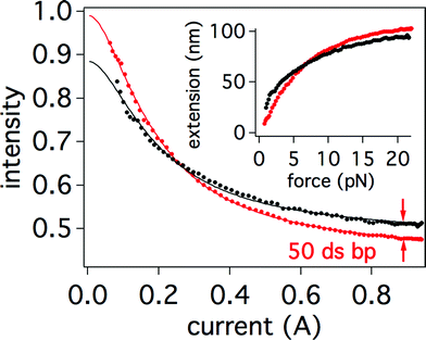 | ||
| Fig. 7 (a) Experimental difference in intensity-current curves (four averaged retraction curves each) after hybridization of a 50-mer to the 200-mer, where the red curve is for fully ssDNA and black curve is for the partially hybridized strand. The scale is based on the initial intensity I0 set to 1 at z = 0. I0 values were obtained from fits to eqn (5) and (8) respectively. Lines indicate fits to data. Inset: same data plotted in terms of extension versus force using the parameters from fitting. The standard deviations of the averaged curves is less than their respective marker sizes. | ||
Verification of self-consistency of the calibration procedure
Hybridization measured by magnetic tweezers
 | (7) |
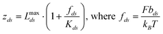
In eqn (7), Kds is the unitless segment elasticity for dsDNA in 150 mM salt conditions (segment elasticity, 1000 pN, normalized by kBT/bds, where bds = 100 nm, or Kds = 24100).32 Although the correction for segment elasticity is small (∼2–3% at most), it is included for consistency with the model for ssDNA stretching. We combined eqn (5) and (7) and applied the logic behind the derivation of the fitting function for the single stranded DNA (see eqn (6)) to arrive at an analogous relationship for a mixed dsDNA-ssDNA model:34
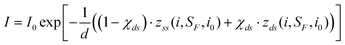 | (8) |
By fitting the ssDNA force curve before hybridization, the penetration depth (d = 139.0 ± 0.3 nm) was obtained along with the sensitivity factor (SF = 24.0 ± 0.2 pN A−1) (see Table 1 at dx = 0.200 cm). Since there is no realignment of either the electromagnet or TIRF angle during addition of the complement, we assume that these parameters do not change. The initial intensity (at i = 0 A), however, is expected to be different for single and partially double-stranded DNA due to appearance of the rigid fragment of dsDNA, so I0 was left as a fitting parameter. Using eqn (8), we found a double stranded fraction of χds = 0.252 ± 0.006 corresponding to 50.4 ± 1.2 bases in the 200-mer strand. This result is a difference of only 0.4 ± 1.2 bases from the theoretical fraction of double stranded character of χds = 0.25. Experimental knowledge of just two parameters, d and SF, from an initial fit to a ssDNA force curve is all that is required in order to determine the double-stranded fraction after hybridization. The initial intensity from the fits before and after hybridization changed from I0,ss = 1.048 ± 0.002 to I0,ds = 0.924 ± 0.001, which corresponds to an increase of ∼17 nm for the initial extension. Since the double stranded section behaves mostly as a rigid rod at low forces, the bead is effectively lifted away from the surface by the distance corresponding to the size of the dsDNA section ∼50 × 0.34 nm = 17 nm, in excellent agreement with the experiment. Therefore, the change in initial intensity is another possible method for detection of the hybridization event. Such a change in initial (zero applied force) intensity can be used to determine the extent of hybridization,10 but probably lacks the near single-base resolution that is offered by applying force and modeling a full mechanical response of the molecule.
The addition of a short primer to a longer ssDNA strand, which is to be sequenced, is a prerequisite for the initiation of the growth of the double-stranded segment using either polymerase or ligase. The 50-mer hybridized to the 200-mer is analogous to such a primer addition and allows for a convenient measure of the initial strand length in situations when the initial contour length is not known.
Since the length of the primer is known, we can factor it out in eqn (8) as follows:
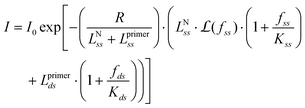 | (9) |
The hybridized intensity-current curve from Fig. 7 is fitted to eqn (9) with fit parameters of I0 and LssN, yielding values of 0.924 ± 0.001 and 86 ± 3 nm, respectively (the fit appears identical to what is shown in Fig. 7). The initial contour length Lssmax can be calculated by simply adding LssN + Lssprimer = 86 ± 3 nm + 29 nm = 115 ± 3 nm. Since a value of 116 nm is expected, this method of first adding a known primer appears to be a good way to estimate the contour length of the original ssDNA strand. Furthermore, the penetration depth can be calculated from R and Lssmax, and was found to be d = 138 ± 3 nm, within ∼1 nm of the expected value of 139 nm.
Once both the penetration depth and contour length of the ssDNA are determined, relative changes in the total hybridization of the ssDNA could be quantified from fitting a subsequent hybridization or base-addition event to eqn (8). If single nucleotide resolution can be achieved in this manner, application of this method to rapid genome sequencing using single nucleotide addition becomes a clear possibility.36 For example, in sequencing by synthesis, detection of extension of the double-stranded portion in a given single DNA molecule in the presence of polymerase and a single substrate (e.g. only dATP) is enough to detect that addition took place and, therefore, to make a base assignment in the original ssDNA molecule. The whole sequence can then be determined by cycling through the remaining three deoxynucleoside triphosphates and repeating the process until the full sequence is established. Force spectroscopy then effectively becomes a tool that detects elongation of the complementary DNA strand by polymerase and operates with single molecule sensitivity (like many fluorescence based systems currently in development).9 SMFS has the potential advantage over fluorescence-based methods in detections of runs of the same bases, because its response scales directly with the number of added bases (size of the double-stranded fragment).
While we designed the model sequence to eliminate the secondary structure as much as possible, future work on this system needs to incorporate the effect of transient secondary structure on force-extension behavior of short ssDNA oligomers. The presence of secondary structure can be mitigated with proper modification to the experiment or detailed analysis (e.g. accounting for shorter contour lengths due to hairpins). For example, one can either maintain a high temperature during the experiment (close to Tm) or focus on analyzing the data derived in the regime of high forces, i.e. above ∼15 pN—the threshold for DNA unzipping37,38—to completely eliminate contributions of secondary structure from experimental data. Since under normal conditions force-induced melting transition in dsDNA is initiated at around 65–70 pN,39 even under high force limitation there will be sufficient dynamic range to acquire force-extension data suitable for interpretation presented in this paper.
Conclusions
We have demonstrated a practical implementation of magnetic tweezers with evanescent nanometry for quantitative detection of DNA hybridization. Individual force-extension curves can be acquired in a continuous manner in 5–10 s. The technique requires no a priori knowledge of either the penetration depth or magnetic properties of the probes, but will yield those values from a fit to the system's equations of state within less than 1–2% error. We validated the use of a fit to the stretching model for ssDNA as a method for internal calibration of both the penetration depth and magnetic force. The simplified model for obtaining both penetration depths and a force calibration from a known DNA strand under standard conditions is especially useful in cases where the differences after a biological event (DNA hybridization, protein binding, polymerization, etc.) are more important than initial characterization of the biomolecule itself.The drawback of the proposed technique is that, in the general case, only the ratio of the molecular counter length to evanescent wave penetration depth can be determined; however, applications of our approach to the detection of changes in molecular conformations (such as hybridization or ligation of the complementary DNA strand) can yield highly accurate values of the penetration depth and the polymer's contour length. As demonstrated here, inclusion of the known length marker (in the case of DNA, an oligomer of known sequence) can provide an alternative way of measuring the penetration depth via pre-determined changes to molecular size (e.g. due to hybridization with a primer or unfolding of a hairpin). While absolute extension measurements are possible with magnetic tweezers using reflection interference contrast microscopy,26 evanescent nanometry does not require a laterally resolved image, only the total intensity, making it possible to view many molecules in parallel with a low-resolution objective. Since magnetic tweezers are a straightforward and cost-effective platform for parallel analysis, potential single-base resolution opens the avenue for a possible rapid genome-sequencing device based on force spectroscopy detection of changes in DNA double stranded content, as described here.
The exponential distance dependence of the evanescent field, on the one hand, makes this technique extremely sensitive to small changes in conformations (with a resolution of 1–2 nucleotides), but on the other, it limits the method to relatively short molecules, <200 nm in a present setup, setting the upper limit for the length of a DNA molecule of interest at several hundred bases. While many next generation sequencing technologies operate on short (20–30 bases) reads, having the benefit of a reference genome, de novo sequencing requires long reads (hundreds of bases). The method described here already operates in this long oligonucleotide regime and it is possible to extend it further by moving to longer laser wavelengths and substrates with a lower index of refraction.
We acknowledge that more work needs to be done on optimization of the surface chemistry, specifically, to increase the number of active tethered microspheres, which is not routine and was not the purpose of this work. Extending the resolution to single-base addition will also require investigating the fluorophore composition of the probes in order to increase their intensity (i.e. signal to noise ratio) and extend their longevity, e.g. by using non-bleaching fluorophores such as quantum dots.
Acknowledgements
This work was supported by NIH grant R21 HG004141. We thank Prof. Daniel K. Schwartz (University of Colorado) for insightful comments on this work and Prof. Stefanie Brachfeld (Montslair State University) for help with the vibrating sample magnetometer measurements.References
- M. Kinjo and R. Rigler, Nucleic Acids Res., 1995, 23, 1795 CAS.
- K. Schmidt, C. Henkel, G. Rozenberg and H. Spaink, Nucleic Acids Res., 2004, 32, 4962 CrossRef CAS.
- G. Yao, X. Fang, H. Yokota, T. Yanagida and W. Tan, Chem.–Eur. J., 2003, 9, 5686–5692 CrossRef CAS.
- Y. Ho, M. Kung, S. Yang and T. Wang, Nano Lett., 2005, 5, 1693–1697 CrossRef CAS.
- S. Kang, Y. Kim and E. Yeung, Anal. Bioanal. Chem., 2007, 387, 2663–2671 CrossRef CAS.
- J. Lee, J. Li and E. Yeung, Anal. Chem., 2007, 79, 8083–8089 CrossRef CAS.
- A. Gunnarsson, P. Jonsson, R. Marie, J. Tegenfeldt and F. Hook, Nano Lett., 2008, 8, 183–188 CrossRef CAS.
- J. W. Efcavitch and J. F. Thompson, Annu. Rev. Anal. Chem., 2010, 3, 109–128 Search PubMed.
- M. Metzker, Nat. Rev. Genet., 2009, 11, 31–46.
- M. Singh-Zocchi, S. Dixit, V. Ivanov and G. Zocchi, Proc. Natl. Acad. Sci. U. S. A., 2003, 100, 7605–7610 CrossRef CAS.
- A. Valbuena, J. Oroz, R. Hervas, A. M. Vera, D. Rodriguez, M. Menendez, J. I. Sulkowska, M. Cieplak and M. Carrion Vazquez, Proc. Natl. Acad. Sci. U. S. A., 2009, 106, 13791–13796 CrossRef CAS.
- M. Bertz, M. Wilmanns and M. Rief, Proc. Natl. Acad. Sci. U. S. A., 2009, 106, 13307–13310 CrossRef CAS.
- U. Bockelmann, P. Thomen and B. Essevaz-Roulet, Biophys. J., 2002, 82, 1537–1553 CrossRef CAS.
- T. T. Perkins, H.-W. Li, R. V. Dalal, J. Gelles and S. M. Block, Biophys. J., 2004, 86, 1640–1648 CrossRef CAS.
- M. Rief, F. Oesterhelt, B. Heymann and H. Gaub, Science, 1997, 275, 1295–1297 CrossRef CAS.
- J. Liang and J. M. Fernandez, ACS Nano, 2009, 3, 1628–1645 CrossRef CAS.
- S. Manohar, A. R. Mantz, K. E. Bancroft, C.-Y. Hui, A. Jagota and D. V. Vezenov, Nano Lett., 2008, 8, 4365–4372 CrossRef CAS.
- M. Kruithof, F. Chien, M. De Jager and J. Van Noort, Biophys. J., 2008, 94, 2343–2348 CrossRef CAS.
- F. Assi, R. Jenks, J. Yang, C. Love and M. Prentiss, J. Appl. Phys., 2002, 92, 5584–5586 CrossRef CAS.
- C. Gosse and V. Croquette, Biophys. J., 2002, 82, 3314–3329 CrossRef CAS.
- J. Abels, F. Moreno-Herrero and T. van der Heijden, Biophys. J., 2005, 88, 2737–2744 CrossRef CAS.
- B. Maier, D. Bensimon and V. Croquette, Proc. Natl. Acad. Sci. U. S. A., 2000, 97, 12002–12007 CrossRef CAS.
- H. I. Lim, P. M. Oliver, J. Marzillier and D. V. Vezenov, Anal. Bioanal. Chem., 2010, 397, 1861–1872 CrossRef CAS.
- D. V Vezenov,U.S. Patent Application, 20080286878, 2008 Search PubMed.
- R. Liu, S. Garcia-Manyes, A. Sarkar, C. L. Badilla and J. M. Fernandez, Biophys. J., 2009, 96, 3810–3821 CrossRef CAS.
- K. Kim and O. A. Saleh, Nucleic Acids Res., 2009, 37, e136–e136 CrossRef.
- N. Ribeck and O. A. Saleh, Rev. Sci. Instrum., 2008, 79, 094301 CrossRef.
- A. Bijamov, F. Shubitidze, P. M. Oliver and D. V. Vezenov, Langmuir, 2010, 26, 12003–12001 CrossRef CAS.
- A. Bijamov, F. Shubitidze, P. M. Oliver and D. V. Vezenov, J. Appl. Phys., 2010, 108 DOI:10.1063/1.3510481 , in press.
- K. B. Towles, J. F. Beausang, H. G. Garcia, R. Phillips and P. C. Nelson, Phys. Biol., 2009, 6, 025001 Search PubMed.
- I. Rouzina and V. Bloomfield, Biophys. J., 2001, 80, 882–893 CrossRef CAS.
- S. B. Smith, Y. Cui and C. Bustamante, Science, 1996, 271, 795–799 CrossRef CAS.
- S. Cui, Y. Yu and Z. Lin, Polymer, 2009, 50, 930–935 CrossRef CAS.
- L. Shokri, M. J. McCauley, I. Rouzina and M. C. Williams, Biophys. J., 2008, 95, 1248–1255 CrossRef CAS.
- D. B. McIntosh, N. Ribeck and O. A. Saleh, Phys. Rev. E: Stat., Nonlinear, Soft Matter Phys., 2009, 80, 041803 CrossRef CAS.
- C. W. Fuller, L. R. Middendorf, S. A. Benner, G. M. Church, T. Harris, X. Huang, S. B. Jovanovich, J. R. Nelson, J. A. Schloss, D. C. Schwartz and D. V. Vezenov, Nat. Biotechnol., 2009, 27, 1013–1023 CrossRef CAS.
- M. Zwolak and M. Di Ventra, Rev. Mod. Phys., 2008 Search PubMed.
- B. Essevaz-Roulet, U. Bockelmann and F. Heslot, Proc. Natl. Acad. Sci. U. S. A., 1997, 94, 11935–11940 CrossRef CAS.
- M. Williams, J. Wenner, I. Rouzina and V. Bloomfield, Biophys. J., 2001, 80, 874–881 CAS.
Footnote |
| † Electronic supplementary information (ESI) available: SEM images, magnetic properties, and force versus field estimates for magnetic-fluorescent probes. Evanescent field penetration depth from simultaneous AFM/TIRF measurement. Noise estimate from immobilized probes. Sample raw intensity-current data. Conversion of intensity fluctuations to force. See DOI: 10.1039/c0nr00479k |
| This journal is © The Royal Society of Chemistry 2011 |