Facile fabrication of porous chitosan/TiO2/Fe3O4 microspheres with multifunction for water purifications†
Zhaoyang
Liu
*,
Hongwei
Bai
and
Darren Delai
Sun
*
School of Civil & Environmental Engineering, Nanyang Technological University, Singapore 639798. E-mail: zyliu@ntu.edu.sg; DDSun@ntu.edu.sg; Fax: +65 68615254; Tel: +65 65921778
First published on 18th October 2010
Abstract
In this work, we came up with a novel concept to fabricate a new kind of composite chitosan/TiO2/Fe3O4 microspheres, which possess highly adsorptive, photocatalytic and magnetic properties. These multi-functional microspheres produced by electrospraying, a facile and low-cost method, have great engineering applications as high-efficiency and reusable materials for the removal of contaminants in water.
Introduction
With the rapid industrialization over the past few decades, the demand for clean water supply as well as the volume of wastewater generated has increased significantly. Conventional membrane water reclamation is heavily used for producing clean water with a small footprint size.1 However, a huge amount of electricity that is needed for membrane water reclamation is an obstacle.2 This obstacle paints an image of being ‘energy expensive’ thus possesses a major challenge with the need to curb greenhouse gases. There is an urgent need to invent a new technology which will be able to solve these existing problems, thus keeping the fast pace of world's economic development.Chitosan, the second-most abundant polysaccharide, has been used as a carrier for drug delivery because of its biocompatibility and low cost.3,4 Recently, chitosan has been found as a superhigh-capacity adsorbent for contaminant removal in water. The adsorption capability of reactive dyes in wastewater using chitosan was reported at 1000–1100 g kg−1,5 which is several times larger than activated carbon, a common adsorbent widely used in the industry. This high adsorption capacity of chitosan is due to the high contents of amino and hydroxyl functional groups on its surface, forming high binding ability between chitosan and contaminants.6 The regeneration of chitosan using acid or base is rather simple and cost effective. However, the application of acid or base for the regeneration of chitosan is not always technically advantageous.7 The large amount of wastewater generated from its regeneration process needs further treatment, making the process non-environmental-friendly and non-sustainable.
Nano TiO2 is a highly active photocatalyst which is able to generate free hydroxide radicals when UV light is struck at its surface.8,9 This photocatalytic process can completely decompose almost all the contaminants in water under moderate conditions, which is economical and environmental friendly. The property of TiO2 has been intensively explored for self-cleaning,10 disinfecting,11 and anticancer.12 Therefore, we try to use the ability of nano TiO2 photocatalyst for in situ removal of contaminants adsorbed by chitosan to regenerate it without the use of acid or base solutions, hence to avoid the generation of wastewater with secondary pollutions.
The effective separation of the spent chitosan and nano TiO2 photocatalyst from treated water for recovery and reuse is another challenge. Magnetic Fe3O4 nanoparticles have received great attentions for site-selective drug delivery.13 For example, functionalised magnetic nanoparticles could be moved to targeted locations by an external magnetic field.14,15 Therefore, if a composite of chitosan and nano TiO2 photocatalyst was magnetic, it could be readily separated and recovered from treated water by the application of an external magnetic field, which opens a new door for easy and cost effective recovery of such adsorbents after water treatments. In addition, microspheric materials are favorable in water treatment because of their high surface area and ease for engineering application, compared with nanoparticles that present some drawbacks in separation and recovery from treated water because of their small sizes, which are commonly in the form of unstable aggregate in water.16
In this study, we designed a new kind of functional composite materials, chitosan/TiO2/Fe3O4 microspheres (CTF-M) to meet the need of high adsorption, self-regeneration, easy separation and cost effective water treatment. The CTF-M, made of chitosan matrix with TiO2 and Fe3O4 nanoparticles embedded inside, was fabricated by a simple electrospraying technology, which can produce micro-size particles at industrial scale.17 The advantages of the present CTF-M are the following: (1) high-capacity adsorbent because of strong binding ability of chitosan matrix for contaminants; (2) in situ self-regeneration with UV light because of photocatalytic reaction, which is an environmental friendly and sustainable process; (3) favorable microspheric morphology and magnetic property for easy and cost effective recovery and reuse. Thus, this new composite microsphere has great potential to be used as an economical, environmentally friendly and sustainable material for large scale water treatment applications.
Experimental
CTF-M microspheres preparation
10 mL of chitosan (2.0 wt%) in acetic acid was mixed with 0.05 g Fe3O4 nanoparticles and 0.05 g Degussa P25 TiO2 nanoparticles in a beaker under ultrasonic. This resulting precursor for CTF-M was drawn into a 10 mL syringe and perfused through a steel capillary of 0.7 mm internal diameter using a Harvard syringe pump (PHD-4400) and subjected to electrohydrodynamic atomisation (Fig. 1). The solution was pumped at a flow rate of 100 μL min−1. The voltage used was 9 kV. Ion induced gelation was used as the primary mechanism of preparing the chitosan microspheres. 80 mL of distilled water with 0.1 g of NaOH was used as the collection solution, which could instantly gel the droplets of electrosprayed chitosan. The chitosan droplets in the collection solution kept spherical shape during the process. The as-prepared CTF-M microspheres were collected by a magnet. The samples were freeze-dried or heat-dried for storage.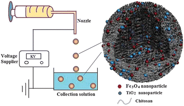 | ||
| Fig. 1 Schematic diagram of the electrospraying technique for producing CTF-M. Left, the electrospraying equipment. Right, schematic structure of CTF-M. | ||
Adsorption capacity of CTF-M
The adsorption capacity of CTF-M was characterised by their AO7 dye uptakes. 10 mg of CTF-M was added to 100 mL of AO7 with concentration of 0.2 g L−1 in distilled water. The suspensions were kept in a shaker at room temperature during 24 h, which is enough for guaranteeing adsorption equilibrium of AO7 over CTF-M surfaces. The CTF-M suspensions were next collected by a magnet, and the residual AO7 contained in the solution was quantified by UV–Vis spectrophotometry at a fixed wavelength of 486 nm.Photocatalytic activity of CTF-M
20 mg of CTF-M was added to 30 mL of AO7 with a concentration of 2.0 × 10⁻⁵ M in distilled water. The CTF-M suspensions were stirred under UV light (365 nm) and the residual AO7 in the solution was tested by UV–Vis spectrophotometry.Characterization methods
Surface morphologies were examined with a ZEISS EVO 50 scanning electron microscope (SEM). The optical photos were taken with an optical microscope (OLYMPUS SZX9). UV–vis measurements were taken with a Shimadzu UV-1700 spectrophotometer. TOC was measured by means of a Tekmar Dohrmann Apollo 9000 TOC analyzer. The structure was analyzed by X-ray diffraction (Bruker AXS Advance) with graphite-monochromatized Cu Kα radiation. Functional groups were obtained on Fourier transform infrared (FTIR) spectrometer (Perkin Elmer, Spectrum GX). The magnetic property was determined with a Vibrating Sample Magnetometer (Lakeshore 7300) (1.5 T) with an applied field of between −5000 and 5000 Oe. Christ Freeze Dryer Alpha 1-2 was used for drying samples.Results and discussion
In this process, a precursor solution containing chitosan, TiO2 and Fe3O4 nanoparticles was sprayed out through a nozzle, under a high-voltage electric field, into a solidifying solution to form microspheres by one step, as shown in Fig. 1 (left). The advantages of this method are: (1) the process is simple and economical, which is suitable for industrial production; (2) Smaller (micrometre) particles can be easily made, compared with millimetre particles by conventional methods, such as, dropping by gravity;5 (3) easy to make composite microspheres with a simple mixing of multi-components in the precursor solutions. In Fig. 1 (right), the structure of these microspheres is schematically depicted. The matrix material of microspheres is chitosan, while TiO2 and Fe3O4 nanoparticles are embedded in the chitosan matrix.Fig. 2a shows the optical image of the as-prepared CTF-M in water. The CTF-M is spherical shape and almost uniform-size. The microsphere diameter is about 500 μm. The SEM image in Fig. 2b also shows the composite CTF-M is spherical in shape and uniform in size, similar as the optical image in Fig. 2a. The microsphere diameter in SEM image is about 400 μm, which is smaller than that in optical image, this is because these microspheres were shrunk after drying for sample preparation of SEM.
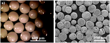 | ||
| Fig. 2 Optical (a) and SEM (b) images of CTF-M composite microspheres. | ||
The structure of CTF-M microspheres was characterized by X-ray diffraction. Fig. 3a shows typical XRD patterns of TiO2 nanoparticles, Fe3O4 nanoparticles and CTF-M, respectively. The peaks in CTF-M match well with those of Fe3O418 and TiO219nanoparticles, which indicate TiO2 and Fe3O4 nanoparticles were successfully embedded in the CTF-M microspheres. Fig. 3b shows the FTIR spectra of pure chitosan and CTF-M. The major peaks in Fig. 3b can be assigned as follows: 3445 cm−1 (O–H and N–H stretching vibrations) and 1640 cm−1 (N–H deformation vibration) of chitosan.20 The main peaks of CTF-M are similar to those of pure chitosan, which indicates chitosan is the matrix materials of CTF-M microspheres. According to XRD and FTIR, the as-prepared CTF-M microspheres are made of chitosan matrix with TiO2 and Fe3O4 embedded inside, as shown in Fig. 1 (right).
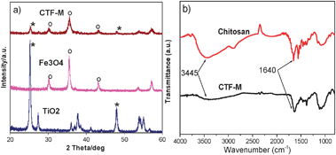 | ||
| Fig. 3 (a) XRD patterns of TiO2 nanoprticles, Fe3O4 nanoparticles, and CTF-M composite microspheres. (b) FTIR spectra of pure chitosan and CTF-M composite microspheres. | ||
Fig. 4a shows the adsorption capacities of AO7 dye onto freeze-dried CTF-M, heat-dried CTF-M and CAC. The adsorption capacities of the dye onto CTF-M microspheres are much higher than those of commercial activated carbons, which is a common adsorbent widely used in water treatment plant for color removal. This could be due to the surfaces of CTF-M microspheres having much more functional groups, which can act as binding sites for contaminants in water, than those of CAC. This result indicates that CTF-M is an ideal candidate as high-efficiency adsorbent to substitute CAC in the industry.5 From Fig. 4a, it can be seen that the adsorption capacities of freeze-dried CTF-M are higher than that of heat-dried CTF-M. At higher magnifications of SEM in Fig. 4b and c, the surface of freeze-dried CTF-M is more porous than that of heat-dried CTF-M. Clearly, porous structure contributes to the easy transportation of contaminants into CTF-M to reach the inside internal surfaces of chitosan microspheres, which results in higher adsorption capacity.
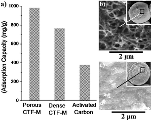 | ||
| Fig. 4 (a) Adsorption capacities of Acid Orange 7 (AO7) dyes onto freeze-dried CTF-M, heat-dried CTF-M and commercial activated carbon (CAC); SEM images of the surfaces on (b) freeze-dried CTF-M and (c) heat-dried CTF-M. | ||
Magnetic measurements of Fe3O4 nanoparticles and CTF-M were investigated with a vibrating sample magnetometer (VSM).14 The hysteresis loops of Fe3O4 nanoparticles and CTF-M microspheres are shown in Fig. 5a. It can be seen that both materials show ferromagnetic behavior. The magnetic saturation values of Fe3O4 nanoparticles and CTF-M are 58 and 19 emu g−1, respectively. The decrease in magnetic saturation for CTF-M is attributed to the cover of chitosan matrix on the surface of magnetic Fe3O4 nanoparticles. However, such a magnetic property is strong enough for the as-prepared CTF-M to be easily separated from water under a magnetic field. The magnetic effect of CTF-M under an external magnetic field is shown in Fig. 5b. Clearly, the CTF-M can be easily and quickly separated from water with the help of an external magnet, which proves that magnetic property of the as-prepared CTF-M is strong enough for easy recovery and reuse from the treated water.
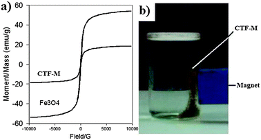 | ||
| Fig. 5 (a) Magnetic properties of Fe3O4 nanoparticles and CTF-M. (b) Demonstration of magnetic separation of CTF-M in water by a magnet. The brown powders attracted to the side of the vial are CTF-M, and the blue bar is a magnet. | ||
The photocatalytic activity of CTF-M was demonstrated by a photocatalytic degradation of AO7 in water. As shown in Fig. 6, the photocatalytic decomposition of AO7 by CTF-M was very fast, and the AO7 solution had almost completely decolourized after illumination with UV light for 120 min. It was observed that without adding in CTF-M, only a slow decrease in the concentration of AO7 was detected under UV irradiation (data were not shown), which proves that the addition of CTF-M obviously accelerates the degradation of AO7. The changes in total organic content (TOC) over the course of the photocatalytic degradation reaction are shown in Fig. S1 (ESI†), which clearly indicates that just with UV-light exposure, the AO7 can be completely mineralized. This high photocatalytic activity can give CTF-M an economical, environmental friendly and sustainable function of self-regeneration. We also did the control experiments of adsorption with CTF-M microspheres without UV light irradiation. As shown in Fig. S2 and S3 (ESI†), with the same experimental conditions, the colour and TOC removal rate (240 min and 330 min, respectively) of AO7 without UV light irradiation are almost one time slower than the corresponding rates (120 min and 160 min, respectively) with UV light irradiation in Fig. 6 and Fig. S1 (ESI†). It is obvious that there are some synergic activities with the combination of adsorption and photodegradation functions of CTF-M microspheres, which shows better effect in the dye removal than the single adsorption without UV light irradiation. After the photocatalytic reaction, the CTF-M was easily collected by a magnet for reuse. The reusability of the recovered CTF-M then was tested. The results are given in Fig. S4 (ESI†). It can be seen that a slight loss of adsorption capacity was observed after 8 times of reuse, which indicates the CTF-M are reusable.
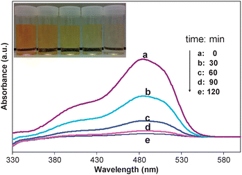 | ||
| Fig. 6 Absorption spectra of AO7 (2.0 × 10⁻⁵ M, 30 mL) solutions in the presence of CTF-M (20 mg) under various UV light irradiation time. The inset photos show the colour reduction with increase of UV light irradiation time correspondingly. | ||
Conclusions
In summary, a new kind of composite microspheres, CTF-M, were produced by a simple method. These multi-functional microspheres possess highly adsorptive, self-regenerative and reusable properties, which have great potential as high-efficiency, cost effective and environment-friendly materials for large scale engineering applications for the removal of contaminants in water.Acknowledgements
We are grateful for the financial support received from the Prime Minister's Office of Singapore via an initiative called The Enterprise Challenge under award number P00579/1273, Singapore Environment & Water Industry (EWI) Development Council under award number MEWR 621/06/166 and the Public Utilities Board of Singapore. We would like to thank Mr Jonathan Lee for drawing the schematic structure of CTF-M.Notes and references
- M. A. Shannon, P. W. Bohn, M. Elimelech, J. G. Georgiadis, B. J. Marin and A. M. Mayes, Nature, 2008, 452, 301 CrossRef CAS.
- T. Y. Cath, A. E. Childress and M. Elimelech, J. Membr. Sci., 2006, 281, 70 CrossRef CAS.
- W. Wei, L. Yuan, G. Hu, L. Wang, J. Wu, X. Hu, Z. Su and G. Ma, Adv. Mater., 2008, 20, 2292 CrossRef CAS.
- Z. Haidara, R. Hamdyb and M. Tabrizian, Biomaterials, 2008, 29, 1207 CrossRef.
- M. Chiou, P. Ho and H. Li, Dyes Pigm., 2004, 60, 69 CrossRef CAS.
- M. V. Singha, A. K. Sharmaa and R. Sanghib, J. Hazard. Mater., 2009, 166, 327 CrossRef.
- V. Singh, A. Sharma and R. Sanghi, J. Hazard. Mater., 2008, 166, 327.
- J. Park, S. Bauer, K. von der Mark and P. Schmuki, Nano Lett., 2007, 7, 1686 CrossRef CAS.
- Z. Liu, X. Quan, H. Fu, X. Li and K. Yang, Appl. Catal., B, 2004, 52, 33 CrossRef CAS.
- R. Wang, K. Hashimoto, A. Fujishima, M. Chikuni, E. Kojima, A. Kitamura, M. Shimohigoshi and T. Watanabe, Nature, 1997, 388, 431 CrossRef CAS.
- P. Evans and D. W. Sheel, Surf. Coat. Technol., 2007, 201, 9319 CrossRef CAS.
- A. Fujishima, T. N. Rao and D. A. Tryk, J. Photochem. Photobiol., C, 2000, 1, 1 CrossRef CAS.
- Z. Liu, G. Yi, H. Zhang, J. Ding, Y. Zhang and J. Xue, Chem. Commun., 2008, 694 RSC.
- Z. Liu, J. Ding and J. Xue, New J. Chem., 2009, 33, 88 RSC.
- N. Shrestha, J. Macak, F. Schmidt-Stein, R. Hahn, C. Mierke, B. Fabry and P. Schmuki, Angew. Chem., Int. Ed., 2009, 48, 969 CrossRef CAS.
- Z. Liu, D. D. Sun, P. Guo and J. O. Leckie, Chem.–Eur. J., 2007, 13, 1851 CrossRef CAS.
- Z. Liu, D. D. Sun, P. Guo and J. O. Leckie, Nano Lett., 2007, 7, 1081 CrossRef CAS.
- K. Bhattacharyya, S. Varma, A. Tripathi, S. Bharadwaj and A. Tyagi, J. Phys. Chem. B, 2009, 113, 5917 CrossRef CAS.
- P. Yang, Z. Quan, Z. Hou, C. Lia, X. Kang, Z. Cheng and J. Lin, Biomaterials, 2009, 30, 4786 CrossRef CAS.
- Z. Zainal, L. Hui, M. Hussein, A. Abdullah and I. Hamadneh, J. Hazard. Mater., 2009, 164, 138 CrossRef CAS.
Footnote |
| † Electronic supplementary information (ESI) available: Experimental details and figures of TOC changes and reusability. See DOI: 10.1039/c0nj00593b |
| This journal is © The Royal Society of Chemistry and the Centre National de la Recherche Scientifique 2011 |
