Uncovering the structural stabilities of the functional bismuth containing oxides: a case study of α-Bi2O3 nanoparticles in aqueous solutions†
Lei
Huang
a,
Guangshe
Li
b,
Tingjiang
Yan
b,
Jing
Zheng
a and
Liping
Li
*a
aKey Laboratory of Optoelectronic Materials Chemistry and Physics, Fujian Institute of Research on the Structure of Matter and Graduate School of Chinese Academy of Sciences, Chinese Academy of Sciences, Fuzhou 350002. E-mail: lipingli@fjirsm.ac.cn
bState Key Lab of Structural Chemistry, Fujian Institute of Research on the Structure of Matter and Graduate School of Chinese Academy of Sciences, Fuzhou 350002
First published on 19th October 2010
Abstract
The majority of bismuth containing oxides have been taken as important functional materials for applications including photocatalytic water splitting and highly conductive solid electrolytes, which however suffer from property degradation owing to the presence of intermediates. This work initiated a case study on α-Bi2O3 nanoparticles with an aim to uncover the origin of property degradation when bismuth oxides that contain traces of secondary phase α-Bi2O3 were exposed in either air or aqueous solutions. First, α-Bi2O3 nanoparticles with spherical and rod-like morphologies were prepared by developing solution chemistries. It was found that α-Bi2O3 transformed partially to Bi2O2CO3 when stored in air for 6 months. Such transformation was further accelerated when α-Bi2O3 nanoparticles were exposed to water or methylene blue (MB) solution, probably because α-Bi2O3 reacts with the species HCO3− as formed by dissolution of CO2 from air. Bi2O3 surfaces had an unusual tendency to adsorb MB molecules, which in turn prevented the reaction between α-Bi2O3 and HCO3−. Consequently, MB solution became clear even without light irradiation. The results reported in this work may help to fully comprehend the property degradation of bismuth containing oxides when used in aqueous solutions.
1. Introduction
As an important multi-functional material, bismuth containing oxides have shown many potential applications in photovoltaic cells, nonlinear optical glasses, fuel cells, oxygen sensors, and catalysis for industrial selective oxidation reactions.1–4 These broad applications are based on its excellent properties like adjustable band gap, high ion conductivity, and rich polymorphism.5Depending on the preparation methods, bismuth containing oxides may have traces of unreacted secondary phase of Bi2O3, which however may contribute greatly to the total properties in an uncontrolled way because of the polymorphs with distinct nature. For instance, Bi2O3 owns six polymorphs6,7 including the monoclinic (α), tetragonal (β), bcc (γ), fact (δ), orthorhombic (ε), and triclinic (ω). Among these polymorphs, α-phase is thermodynamically stable and has a direct energy band gap of 2.8 eV.8 Electrons in the valence band of α-Bi2O3 could be excited by visible light for activating useful properties. For these reasons, preliminary efforts have been devoted to exploring the possible uses of α-Bi2O3 for solar energy conversion and environmental purification. For example, Zhang et al. prepared Bi2O3 by sonochemical route to degrade the methyl orange under visible light.8 Eberl et al.9 prepared Bi2O3 from a series of starting material using three different methods and concluded that photocatalytic activities in 4-chlorophenol degradation at λ ≥ 420 nm are strongly dependent on the sample preparation conditions. Recently, Bi2O3 was also reported to act as the substrates or photo sensitizers. Hameed et al.10 found that ZnO–Bi2O3 composites have the promoted activities under UV-vis irradiation in degradation of methylene blue, methyl orange, and phenol. In spite of these great efforts, it still remains uncertain as to the property degradation in the case when Bi2O3 appears as the secondary phase of bismuth containing oxides for applications in water or other aqueous solutions.
Therefore, it is highly necessary to investigate the durability of Bi2O3 in water, because (1) it may help to uncover the structural stabilities of bismuth containing oxides for applications in solar energy conversion and environmental purification where water (or CO2) exists popularly, (2) it allows the comprehension of the surface compositions that activate the chemical reactions of bismuth compounds. It is well established that bismuth containing oxides are not stable in air, and thus their surfaces are usually covered by layers of secondary phases, which have contributed greatly to the activities for chemical reactions.11,12
In this work, we prepared α-Bi2O3 with different morphologies by two solution chemistries and investigated their stabilities when exposed to water or methylene blue solution upon long-term storage in air. It was found that α-Bi2O3 nanoparticles easily reacted with CO2 and formed Bi2O2CO3, and that the formation process of Bi2O2CO3 in water was different from that in MB solution because of the involvement of species HCO3− when dissolution of CO2 from air. The reaction-adsorption model of α-Bi2O3 with HCO3− in MB solution was proposed and experimentally evidenced.
2. Experimental
2.1 Sample preparation
Bi2O3 nanoparticles were prepared by two approaches. Method I: Bi (NO3)3·5H2O (A.R.), NaOH (A.R.), and HNO3 (65%, A.R.) were used as the starting materials. The synthetic processes can be described as follows: Firstly, 1 mL HNO3 was added into 19 mL H2O, into which 3.123 g Bi(NO3)3·5H2O was dissolved to get a clear solution. Then, an aqueous solution of NaOH with the given molar ratio was added into the above clear solution with continuous stirring. The as-obtained suspension was transferred to a Teflon-lined stainless steel autoclave with a filling capacity of about 80%, sealed, and reacted at 200 °C for 12 h. The autoclave was then cooled naturally to room temperature. The product was harvested by pressure filtration, washed fully with distilled water, and dried at 80 °C for 12 h. The sample thus obtained was named as Aas.Method II: Bi2O3 nanoparticles were prepared from the precursor of BiOCl nanosheets. BiOCl was produced following the procedure reported in reference13 which used a mechanochemical processing method including milling, heat-treatment, and subsequent washings. Namely, BiCl3, Na2CO3 and NaCl were milled in an agate mortar for 15 min with the fixed molar ratios of 1![[thin space (1/6-em)]](https://www.rsc.org/images/entities/char_2009.gif) :1.5:5. The reactant mixture was heated in air at 325 °C for 3 h and was then washed several times and dried at 80 °C for 12 h to get BiOCl precursor. To obtain the Bi2O3 nanoparticles, 0.5 g BiOCl precursor was dispersed into 10 mL ethanol to form a white suspension solution, into which 4 mL NaOH (2 mol L−1) was added into the above solution with continuous stirring. After stirring for 3 h and sonicating for 1 h at room temperature, the suspension color changed from white to yellow. The residual precipitate was washed with distilled water and ethanol several times, and dried at 80 °C for 12 h to get the sample Bas.
:1.5:5. The reactant mixture was heated in air at 325 °C for 3 h and was then washed several times and dried at 80 °C for 12 h to get BiOCl precursor. To obtain the Bi2O3 nanoparticles, 0.5 g BiOCl precursor was dispersed into 10 mL ethanol to form a white suspension solution, into which 4 mL NaOH (2 mol L−1) was added into the above solution with continuous stirring. After stirring for 3 h and sonicating for 1 h at room temperature, the suspension color changed from white to yellow. The residual precipitate was washed with distilled water and ethanol several times, and dried at 80 °C for 12 h to get the sample Bas.
2.2 Stability test of Bi2O3 nanoparticles
The stabilities of Bi2O3 nanoparticles were measured by exposing to water or dye solution. 150 mg Bi2O3 nanoparticles (Aas or Bas) were first put in 150 mL H2O or 5 × 10⁻⁵ mol L−1methylene blue (MB) solution, while continuously stirring at ambient conditions for 1 h, 2 h, 4 h, 8 h, and 16 h, respectively. When exposing to the dye solution, a black bag was used to shade the external light. Residual precipitations were harvested by pressure filtration directly and dried at room temperature for further characterization. To reveal the influence of organic dye on the stability of Bi2O3 nanoparticles, 3 mL of the reacted MB suspensions were extracted and centrifuged at a rate of 9000 rpm for 15 min. The residual solutions were taken for UV-vis absorption spectrum measurements. Similar experimental procedure was also applied when exposing Bi2O3 nanoparticles to water. The samples were denoted as Awat–nh when the residue is a consequence of exposing Aas to water for n h, or Adye−nh when the residue is a consequence of exposing Aas to dye solution for n h. To justify the role of CO2 in the reaction, the stabilities of samples Aas and Bas were also exposed to water for 16 h under oxygen conditions in a glove box, which led to the samples Aoxy-16h and Boxy-16h, respectively. The stabilities of the samples Aas and Bas were also investigated after storage in air for a long-period of time like six months, which led to the samples Astor and Bstor.2.3 Sample characterization
Phase compositions of the samples were identified by powder X-ray diffraction on a Miniflex II diffractometer using Cu-Kα radiation at room temperature. The morphologies of the samples were studied by a field-emission scanning electron microscopy (FE-SEM) using a JEOL JSM-6700 apparatus, and transition electron microscopy (TEM) on a JEOL JEM 2010 instrument under an acceleration voltage of 200 kV. Samples for TEM observations were prepared by making dispersion of the samples in ethanol and putting drops of them on a carbon-coated copper grid. The elemental composition of the sample was determined using Ultima inductively coupled plasma spectrometry and Vario MICRO elemental analyzer. The infrared optical properties were measured on a Perkin-Elmer IR spectrophotometer at a resolution of 4 cm−1 using a KBr pellet technique.Valence states of the bismuth ions for the samples were determined by X-ray photoelectron spectroscopy (XPS). XPS measurements for powder samples fixed on double-sided tapes were performed on an ESCA-LAB MKII X-ray photoelectron spectrometer from VG Co. with Al Kα radiation. The base pressure was 10−7 Pa and the C 1s signal was used to correct the charge effects. The UV-vis absorption spectra of MB solution were measured on a Perkin Elmer UV WinLab Lambda 35 spectrophotometer.
3. Results and discussion
3.1 Stability of Bi2O3
XRD patterns of the as-prepared samples Aas and Bas are illustrated in Fig. 1. The strong diffraction lines indicate the high crystallinity.14 Careful diffraction data analysis showed that both samples crystallized in a monoclinic structure, since all diffraction peaks matched well the standard data for α-Bi2O3 (JCPDS, No. 71-2274). The diffraction lines for other polymorphs of Bi2O3 were hardly seen, which demonstrates single phase nature. However, when the as-prepared samples were stored in air for 6 months under ambient conditions, XRD patterns changed a lot. For sample Astor, an extra weak diffraction line was detected at two theta of 30.3°. Comparatively, sample Bstor exhibited several relatively strong peaks at two theta of 12.9, 24.0, 30.3, and 32.7° in addition to the characteristic diffraction peaks for α-Bi2O3. These new peaks belonged to the planes (101), (013), and (110) for Bi2O2CO3 (JCPDS, No. 41-1488). The occurrence of the secondary phases for both Astor and Bstor was also confirmed by SEM and elemental analysis (see Table S1†). For sample Aas, as illustrated in Fig. 2, the nearly spherical particles with dimension of several microns are predominant. Alternatively, sample Bas is mainly composed of rod-like particles with diameters of several hundreds of nanometres. It is also noted that the morphology of sample Astor is nearly the same as sample Aas, although some particle–particle attachments appeared at particle corners. Instead, sample Bstor showed a remarkably different morphology from Bas. Rod-like particles with smooth surfaces could hardly be seen, except for many plate-like particles. These plate-like particles could be ascribed to Bi2O2CO3. These observations indicate that Bi2O3 nanoparticles are not stable at ambient conditions and would react with CO2 to form Bi2O2CO3 in air. | ||
| Fig. 1 XRD patterns of the as-prepared samples Aas, Bas, Astor, and Bstor. The standard diffraction data for α-Bi2O3, B2O2CO3, and (BiO)4CO3(OH)2 are also shown for comparison. | ||
 | ||
| Fig. 2 SEM images of samples Aas, Bas, Astor, and Bstor. | ||
Comparatively, transformation from Bi2O3 to Bi2O2CO3 in water is relatively easier due to the existence of CO2/H2CO3. Fig. 3 shows the XRD patterns for the samples after exposing Aas and Bas to water. It is seen that after exposing Aas to water for 1 h, the characteristic diffraction line (110) at two-theta of 32.7° for Bi2O2CO3 was observed for Awat-1h. Prolonging the exposure time led to the strengthened diffraction intensity for Bi2O2CO3. A similar phenomenon was observed when exposing Bas to water for less than 4 h (Fig. 3b). When prolonging the exposure time to 8 h, Bi2O2CO3 became the dominant phase. Further prolonging the exposure time to 16 h, the diffraction peaks of parent phase α-Bi2O3 in Bwat-16h became extremely weak, and sample Bwat-16h showed a white color that is distinct from the yellow color for sample Bas. It should be noted that at two-theta of about 18°, a weak diffraction peak for Teflon (JCPDS, No. 47-2217) was detected when samples Aas and Bas were exposed to water for more than 8 h. Alternatively, when samples Aas and Bas were exposed to water under a flow oxygen, both samples Aoxy-16h and Boxy-16h contained much less Bi2O2CO3 than that without flowing oxygen (i.e., Awater-16h and Bwater-16h). The diffraction peaks belonging to (BiO)4CO3(OH)2 were detected. The formation of (BiO)4CO3(OH)2 should be related to the low CO2 pressure under oxygen atmosphere.15
 | ||
| Fig. 3 XRD patterns of the samples obtained by exposing (a) Aas and (b) Bas to water in dark for given period of time. Vertical bars represent the standard diffraction data for α-Bi2O3, B2O2CO3, and (BiO)4CO3(OH)2. | ||
Morphologies of the water exposed samples were investigated by TEM. As shown in Fig. 4, Awat-16h and Bwat-16h were mainly plate-like structures with dimensions larger than 200 nm. High-resolution TEM (HRTEM) images of the samples Awat-16h and Bwat-16h (Fig. 4) revealed the clear fringes, which indicates a single-crystalline nature.16 These fringes were separated by a spacing of 0.273 nm, consistent with the inter-planar spacing of plane (110) for Bi2O2CO3. From these TEM images, it is hard to find the existence of Bi2O3 except for a few core-shell nanostructures in Bwat-16h (inset of Fig. 4). The nanoparticles or nanorods were coated by an amorphous layer of 20 nm in thickness. We believed that the inner nanoparticles or nanorods are the residual Bi2O3, while outer amorphous layer should be Bi2O2CO3. Such core-shell nanostructures were not found in TEM images for Awat-16h.

The results presented above show that α-Bi2O3 is not stable in aqueous solutions. What would happen when Bi2O3 nanoparticles were exposed to MB solution? XRD was used to monitor the processes when Aas and Bas were exposed to MB solution. As indicated in Fig. 5, dual-phase structures as well as the Teflon impurities were observed after exposing to MB solution, as that observed when exposing to water. Nevertheless, different from the yellow color for Awat-16h and white color for Bwat-16h, the sample color for both Adye-16h and Bdye-16h was blue. Sample color change could be closely related to the surface reaction between α-Bi2O3 and CO2/HCO3−. To examine the reaction rate of α-Bi2O3 with CO2/H2CO3 when exposing to water and MB solution, the intensity ratios of diffraction line (110) for Bi2O2CO3 to line (120) for Bi2O3 were calculated. Fig. 6 shows the variations of intensity ratio with the exposure time. It is seen that, (1) Bas exhibited a larger reaction rate than Aas in either water or MB solution, which might be the consequence of the relatively small particle dimension and special rod-like morphology; (2) the intensity ratio for Aas when exposing to water was slightly larger than that when exposed to MB solution; and (3) the intensity ratio kept nearly constant when exposing Aas and Bas to MB solution for a long period of time from 4 to 8 h. These facts imply that the reaction process of α-Bi2O3 with CO2/HCO3− when exposed to MB solution could be different from that when exposed to water.
 | ||
| Fig. 5 XRD patterns of the samples when exposing (a) Aas and (b) Bas to MB solution in dark for given period of time. | ||
 | ||
| Fig. 6 Exposure time dependence of intensity ratios of line (110) for Bi2O2CO3 to line (120) for α-Bi2O3. | ||
3.2 Reaction process and unusual adsorption of Bi2O3 nanoparticles in MB solution
When α-Bi2O3 nanoparticles were exposed to MB solution (5 × 10⁻⁵ mol L−1), α-Bi2O3 reacted with CO2/H2CO3− to form Bi2O2CO3. At the meanwhile, MB solution became clear. When the concentration of MB solution decreased from 5 × 10⁻⁵ to 1 × 10⁻⁵ mol L−1, the solution became nearly colorless (S1†).As is well known, MB is a common cationic dye of broad applications in the fields of chemistry and biology.17,18 In this work, the concentration variation of MB can act as a probe to give the information about the reactions occurred in MB solution. UV-visible absorption spectra of MB solution were used to monitor the fading of MB solution which may in turn help to understand the transformation process of Bi2O3 to Bi2O2CO3. Fig. 7 shows the time-dependent absorption spectra of MB solutions at the presence of Aas and Bas, while the normalized absorbance intensity changes of MB solution with time were also presented. After stirring for 16 h, the normalized absorbance C/C0 decreased by 5% in the presence of Aas, much less than 30% for that contains Bas. It is interesting that C/C0 does not decrease monotonously with prolonging the exposure (or stirring) time. For example, there was one abnormal data point at 4 h for Aas and two data points at 4 and 8 h for Bas. This unusual adsorption of MB molecules on surfaces of Bi2O3 nanoparticles is also reproducible, as indicated when changing the stirring rate (S2†).
 | ||
| Fig. 7 Time-dependent absorption spectra of MB solution in the presence of samples (a) Aas and (b) Bas, and (c) variations of the normalized absorbance intensity with the exposure time. | ||
Many factors such as degradation, pH-induced structure conversion,19 as well as MB adsorption on surfaces of nanoparticles could affect the characteristic absorption intensity for MB molecules. To figure out the reasons for the varied characteristic absorption of MB molecules with exposure time in Fig. 7c, IR spectra of the exposed samples were measured. IR spectra of the typical exposed samples as well as Aas and Bas are compared. As indicated in Fig. 8, a set of bands were observed below 600 cm−1, which are characteristic for Bi–O bonds.20 After exposing to water and MB solution for 16 h, new bands appeared at 1460, 1400, and 850 cm−1, which could be assigned to CO32− vibrations in Bi2O2CO3.21 The multiple bands appeared at 1240, 1215, and 1150 cm−1, which can be assigned to CF2 stretching vibrations of polytetrafluoroethylene (Teflon)22 as originated from the Teflon layers of the magnetic stirrers, as indicated by XRD. Relatively strong vibrations of CO32− for Bwat-16h and Bdye-16h were also observed, which is due to the enriched layers of Bi2O2CO3, consistent with XRD analysis. Compared to Awat-16h and Bwat-16h, no additional bands were detected for Adye-16h and Bdye-16h. It should be emphasized that most of the strong vibrations for MB molecules were overlapped with those of CO32−. Therefore, from IR spectra, it is still difficult to make sure which factor is responsible for the intensity variations of MB characteristic absorption.
 | ||
| Fig. 8 IR spectra of samples Aas, Bas, Awat-16h, Bwat-16h, Adye-16h, and Bdye-16h. | ||
Several implications, however, show that the dye does not undergo decomposition. Firstly, during the adsorption process, the absorption bands of MB did not shift, and no new peaks appeared in the absorption spectra (Fig. 7a and b). Therefore, the variation of absorption intensity is not due to the catalytic degradation or pH-induced structure conversion of MB. As is well known, during MB photodegradation, N-demethylated analogues would contribute to the hypsochromic effect of the absorption band with the maximum at about 660 nm. Correspondingly, the possible colorless intermediates would be revealed by the new strong peaks in UV regions.23,24 On the other hand, pH-induced structure conversion of MB would also result in the shift in the absorption band.19 During the exposure to water and MB solution, the pH of the solution was kept in the range of 6 to 9. Secondly, XPS data (S3†) of Bas demonstrate that Bi3+ ions are predominant, while in Bdye-16h, bismuth ions are in mixed valences of +3 and +5. Bi5+ came from Bi2O2CO3 which would change its color from white to black under light irradiation. This color change is different from the photochromic effect of BiOX (X = Cl, I)25 because it is irreversible. According to the basic principle of redox reaction in inorganic chemistry, oxidizing MB to inorganic molecules such as CO2 and SO42− would lead to the reduction of Bi ions, which is apparently inconsistent with the experimental observations by XPS. Thus, the variation of Bi valence is not the result of MB degradation.
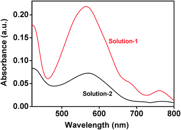
Further, a simple method was designed to verify MB adsorption on surfaces of nanoparticles using UV-visible absorption spectrum. Firstly, Aas was allowed to stay in MB solution (1 × 10⁻⁵ mol L−1) for 9 h, which was then dissolved in diluted hydrochloric acid to get a clear solution with pH = 1 (named as Solution-1). For comparison, pure MB solution (1 × 10⁻⁵ mol L−1) was also adjusted to pH = 1 by diluted hydrochloric acid to get a solution (named as Solution-2). Fig. 9 shows UV-visible absorption spectra of Solution-1 and Solution-2. In the region of 420–800 nm, both solutions exhibited the similar absorptions except for the maximum positions. Namely, the maximum absorption of Solution-2 shifted from 600 nm for pure MB to 564 nm for Solution-1, which indicates the occurrence of pH-induced structure conversion in Solution-1.19 Namely, organic dye is further confirmed to be adsorbed on surfaces of Bi2O2CO3. It can be thus concluded that MB adsorption on surfaces of nanoparticles affected the characteristic absorption intensity for MB molecules at the presence of Bi2O2CO3 (Fig. 7).
 | ||
| Fig. 9 UV-visible spectra of (a) Solution-1 and (b) Solution-2. | ||
Having the adsorption of MB molecules on nanoparticle surfaces in mind, it becomes clear as to the time-dependent variations of intensity ratio of diffraction peaks of Bi2O2CO3 to Bi2O3 in Fig. 6. When exposing to water or MB solution, the formation reaction of Bi2O2CO3 on surfaces of α-Bi2O3 particles may proceed in two steps: (1) the diffusion of CO2/H2CO3− towards the surfaces of α-Bi2O3, and (2) α-Bi2O3 reacted with CO2/H2CO3−. As indicated in Fig. 6, when exposing to water, the supply of CO2/H2CO3− to the surface of Bi2O3 is sufficient. Transformation of Bi2O3 to Bi2O2CO3 happened until Bi2O3 surface was densely covered by Bi2O2CO3 to totally transform into Bi2O2CO3. Alternatively, when exposed to MB solution, the intensity ratio of diffraction peaks of Bi2O2CO3 to α-Bi2O3 kept almost the constant when the exposure time lasted from 4 to 8 h, which means that formation reaction of Bi2O2CO3 was temporarily stopped. Because the reaction rate for Aas is much lower than that for Bas, the temporary reaction stop phenomena observed for both samples could not be ascribed to the insufficient HCO3−. On the contrary, MB molecules would compete with HCO3− to be adsorbed on the surfaces of nanoparticles. When the surfaces of Bi2O3 nanoparticles were covered by MB molecules or Bi2O2CO3, reaction of Bi2O3 with HCO3− to form Bi2O2CO3 would be prevented. Then, prolonged period of time is needed to establish a new adsorption balance between HCO3− and MB molecules on nanoparticles. Such a re-adsorption process could only be achieved by diffusion of HCO3− and MB molecules or by detaching Bi2O2CO3.
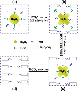
To clearly describe these steps for understanding the unusual MB absorption, a reaction-adsorption model was proposed, as illustrated in Scheme 1. As is well known, MB in solution is weakly basic.26 Therefore, dissolved CO2 in MB solution would transform to HCO3−.27 Similar to what is reported elsewhere,28 surfaces of Bi2O3 nanoparticles prepared by wet chemical routes would be covered by numbers of unsaturated sites of Bi3+ and O2− ions as well as hydroxyl sites. Once HCO3− ions are adsorbed on the surface of Bi2O3 as illustrated in Scheme 1a, these species would react with Bi2O3 to form amorphous Bi2O2CO3 layer (Fig. 4b). This amorphous layer may accumulate and crystallize with prolonging the reaction time. After exposing to MB solution for about 4 h, surfaces of Bi2O3 nanoparticles would be entirely covered by Bi2O2CO3.29 The shear stress from stirring would tear Bi2O2CO3 from the nanoparticles, and the etching of Bi2O2CO3 would give the newly formed Bi2O3 surfaces. To reduce the surface energy, the newly formed Bi2O3 surfaces would adsorb MB molecules notably (Scheme 1b), which may result in the reduction of MB concentration (Fig. 7c). Then, CO2 molecules from air dissolve into the solution to form HCO3−, and the newly formed HCO3− would exchange with MB molecules at surfaces of Bi2O3 (Scheme 1b). As indicated in literature,30 a surface structure-change might be possible during the exchange between MB and HCO3−. The replaced MB molecules would re-dissolve into the solution and thus the MB concentration would increase (Scheme 1c). After several recycles, Bi2O3 was transformed to Bi2O2CO3 completely (Scheme 1d). Therefore, according to the description of Scheme 1 for the adsorption-reaction-etching process occurred on surfaces of α-Bi2O3 nanoparticles, the concentration of MB molecules in aqueous solutions would vary in a fluctuation form, isomorphic to the experiment data in Fig. 7c.
 | ||
| Scheme 1 Reaction- adsorption model proposed for α-Bi2O3 with HCO3− in MB solution. | ||
4. Conclusions
The stabilities of α-Bi2O3 in air and aqueous solution were systematically studied. It is demonstrated that at ambient conditions, α-Bi2O3 transformed partially into Bi2O2CO3 after storage in air for 6 months. This transformation process was accelerated in aqueous solutions, as indicated by the fact that Bi2O2CO3 appeared when α-Bi2O3 nanoparticles of spherical and rod-like morphologies were exposed to water for 2 h and that the content of Bi2O2CO3 increased with prolonging the exposure time. When exposed to MB solution, transformation from α-Bi2O3 to Bi2O2CO3 became complicated in comparison with that in water: there existed an unusual MB adsorption on surfaces of Bi2O3 nanoparticles. The reaction of α-Bi2O3 with HCO3− would be prevented when exposing Bi2O3 nanoparticles in MB solution for a period of time from 4 to 8 h. Meanwhile, the concentration of MB molecules in solution would be fluctuated with exposure time. As a result, MB solution became clear at the absence of light irradiation.Acknowledgements
This work was financially supported by NSFC under the contract (no. 20773132, 20771101, 20831004), National Basic Research Program of China (no. 2009BAE89B01, 2009CB939801, 2007CB613301), and Directional program of CAS (no. KJCXZ-YW-M10).References
- H. T. Fan, X. M. Teng, S. S. Pan, C. Ye, G. H. Li and L. D. Zhang, Appl. Phys. Lett., 2005, 87, 3.
- T. P. Gujar, V. R. Shinde and C. D. Lokhande, Appl. Surf. Sci., 2008, 254, 4186–4190 CrossRef CAS.
- B. J. Yang, M. S. Mo, H. M. Hu, C. Li, X. G. Yang, Q. W. Li and Y. T. Qian, Eur. J. Inorg. Chem., 2004, 1785–1787 CrossRef CAS.
- L. Zhou, W. Z. Wang, H. L. Xu, S. M. Sun and M. Shang, Chem.–Eur. J., 2009, 15, 1776–1782 CrossRef CAS.
- H. A. Harwig and A. G. Gerards, J. Solid State Chem., 1978, 26, 265–274 CrossRef CAS.
- L. Leontie, M. Caraman, M. Alexe and C. Harnagea, Surf. Sci., 2002, 507–510, 480–485 CrossRef CAS.
- M. Drache, P. Roussel and J. P. Wignacourt, Chem. Rev., 2007, 107, 80–96 CrossRef CAS.
- L. S. Zhang, W. Z. Wang, J. O. Yang, Z. G. Chen, W. Q. Zhang, L. Zhou and S. W. Liu, Appl. Catal., A, 2006, 308, 105–110 CrossRef CAS.
- J. Eberl and H. Kisch, Photochem. Photobiol. Sci., 2008, 7, 1400–1406 RSC.
- A. Hameed, V. Gombac, T. Montini, L. Felisari and P. Fornasiero, Chem. Phys. Lett., 2009, 483, 254–261 CrossRef CAS.
- Y. Wang, Y. Y. Wen, H. M. Ding and Y. K. Shan, J. Mater. Sci., 2010, 45, 1385–1392 CrossRef CAS.
- A. Sundaresan, R. V. K. Mangalam, A. Iyo, Y. Tanaka and C. N. R. Rao, J. Mater. Chem., 2008, 18, 2191–2193 RSC.
- A. Dodd, A. McKinley, M. Saunders and T. Tsuzuki, Nanotechnology, 2006, 17, 692–698 CrossRef CAS.
- X. Q. Qiu, L. P. Li, J. Zheng, J. J. Liu, X. F. Sun and G. S. Li, J. Phys. Chem. C, 2008, 112, 12242–12248 CrossRef CAS.
- P. Taylor, S. Sunder and V. J. Lopata, Can. J. Chem., 1984, 62, 2863–2873 CrossRef CAS.
- Y. F. Qiu, D. F. Liu, J. H. Yang and S. H. Yang, Adv. Mater., 2006, 18, 2604 CrossRef CAS.
- L. Gossner, O. Pech, A. May, M. Vieth, M. Stolte and C. Ell, Dig. Liver Dis., 2006, 38, 724–729 CrossRef CAS.
- K. J. Feng, C. H. Sun, Y. Kang, J. W. Chen, J. H. Jiang, G. L. Shen and R. Q. Yu, Electrochem. Commun., 2008, 10, 531–535 CrossRef CAS.
- G. S. Singhal and E. Rabinowi, J. Phys. Chem., 1967, 71, 3347 CrossRef CAS.
- I. Ardelean, S. Cora and D. Rusu, Phys. B, 2008, 403, 3682–3685 CrossRef CAS.
- M. Tsuji, Y. Ikeda, M. Sazarashi, M. Yamaguchi, J. Matsunami and Y. Tamaura, Mater. Res. Bull., 2000, 35, 2109–2121 CrossRef CAS.
- H. Lobo and J. V. Bonilla, Handbook of Plastics Analysis, CRC Press, 2003 Search PubMed.
- C. Yogi, K. Kojima, N. Wada, H. Tokumoto, T. Takai, T. Mizoguchi and H. Tamiaki, Thin Solid Films, 2008, 516, 5881–5884 CrossRef CAS.
- X. Z. Li, G. M. Liu and J. C. Zhao, New J. Chem., 1999, 23, 1193–1196 RSC.
- J. Henle and S. Kaskel, J. Mater. Chem., 2007, 17, 4964–4971 RSC.
- G. Wen, P. G. Cookson, X. Liu and X. G. Wang, J. Appl. Polym. Sci., 2010, 116, 2216–2226 CAS.
- A. A. Gordus, Schaum's Outline of Theory and Problems of Analytical Chemistry, McGraw-Hill Professional, 1985 Search PubMed.
- A. Zecchina, S. Coluccia, E. Guglielminotti and G. Ghiotti, J. Phys. Chem., 1971, 75, 2774–2783 CrossRef CAS.
- C. Schilde, H. Nolte, C. Arlt and A. Kwade, Compos. Sci. Technol., 2010, 70, 657–663 CrossRef CAS.
- T. Kojima, M. Bessho, M. Furuta, S. Okuda and M. Hara, Radiat. Phys. Chem., 2004, 71, 235–238 CrossRef CAS.
Footnote |
| † Electronic supplementary information (ESI) available: Compositional analysis results, photos of MB solution in the presence of Bas with stirring time, and time-dependent concentration variation of MB solution in the presence of Bi2O3 at different stirring rates. See DOI: 10.1039/c0nj00410c |
| This journal is © The Royal Society of Chemistry and the Centre National de la Recherche Scientifique 2011 |