Hollow hemisphere and microcapsules of nonionic copolymer†
Uttam
Manna
and
Satish
Patil
*
Solid State and Structural Chemistry Unit, Indian Institute of Science, Bangalore, 560012, India. E-mail: satish@sscu.iisc.ernet.in; Fax: +91-80-23601310; Tel: +91-80- 22932651
First published on 21st October 2010
Abstract
Hemispherical colloidal nanowells or microwells with hollow interiors are becoming increasingly important for the encapsulation of functional materials. There has been rapid progress to develop new methods to obtain such structures. In this work, we present emulsification approach to generate hemisphere and microcapsules of biocompatible organic polymer. The precise control over the size is exhibited by applying variable vortex effect. The hemispheres and microcapsules of a copolymer (BPVA-PVA) were characterized by scanning electron microscopy (SEM) and confocal laser scanning microscopy (CLSM). These structures were used for loading of hydrophilic molecules and submicron colloidal particles to demonstrate their potential application. The introduction of hydrophobic groups on poly(vinyl alcohol) was crucial to obtain these structures.
Introduction
In the past few years, fabrication of microcapsules and tiny bowls having femtolitre, nanolitre and zeptoliter volume has shown immense impact on chemical, biological and material sciences due to widespread applications of these structures in enzyme mediated reaction kinetics,1 single molecules enzymology,2 PCR analysis,3 and encapsulation of submicron particles.6 But in most of the cases inorganic materials (ZnO,7TiO2,8Fe2O3,9silica derivatives and Au, Ag, Cu, Al)10,11 were employed to fabricate these tiny bowls. Here, we focus our attention to find a similar morphology for organic materials in which it is quite challenging to gain such structures due to structural irregularities and non-rigid nature of the backbone. Well-defined hollow microcapsules of biocompatible polymers have gained significant attention due to their immense application for encapsulation and release of drug, DNA, protein, colloidal particles, cosmetics, food ingredients and flavoring agents etc.12–18,5 Layer-by-layer (LbL) approach is frontier root for the synthesis of these microcapsules.19 This versatile and simple approach was first proposed by Decher on flat substrate.20,21 Then, Caruso and coworkers extended this approach to colloidal particle to fabricate hollow polymer microcapsules.22–24 The LbL self-assembly25 is built based on the sequential adsorption of two complementary polymers from corresponding solution through electrostatic interaction, hydrogen and covalent bonding.26–28 On the other hand various research groups are working on single step methods to obtain polymer microcapsules. Recently, Caruso et al. reported a one step fabrication protocol for microcapsule preparation through oxidative polymerization of dopamine on a sacrificial template and following the removal of this template microcapsules of polydopamine were obtained.29 But in this approach the controlled polymerization of monomer and growth of thin film on the colloidal template is in the same step. In this method, it may be difficult to remove associated side products during the polymerization process and it is limited to small family of monomeric structures. Here, we have described an emulsification approach for deposition of polymer on the sacrificial core using an oil in water stabilizer. So far in literature, this kind of method is reported for the formation of collidosomes.30,31 It is well-known that a colloidal particles undergo a self-assembly process at the interface of the emulsion droplet and forms a big colloidsome.32,33 This assembly is independent of the shape of the material as well.34 In the present method, a colloidal particle is encapsulated inside the emulsion droplets and subsequently hollow single component polymer microcapsules, hemispheres (micro cups) and hollow microspheres were obtained. By optimizing the surface potential of the MF (melamine formaldehyde) particle, we have placed this sacrificial colloidal template within emulsion droplets containing polymer. The polymer gets aggregated at the interface and deposits on the MF particle after removal of organic solvent. On dissolving the colloidal template, different complex architectures of this polymer were obtained such as hemispheres, microcapsules and microspheres. We have demonstrated the concept with biocompatible polymers because these well-controlled polymer hemispheres are useful for different bio-applications including encapsulation of submicron particles and hydrophilic molecules. Encapsulation of submicron particles within hemispheres has been characterized with SEM study. A honeycomb arrangement of hemispheres furnishes potential to investigate these controlled architectures in materials science and biotechnology.4Experimental
Materials
Melamine formaldehyde (MF) (hydrochloric acid, HCl, soluble) particles with 3.3–3.5 μm size from Micro-particles GmbH, Berlin, Germany was obtained as a colloidal template. Chitosan (Mw ≈ 200000), polyvinyl alcohol (Mw ≈ 14000) (from Aldrich), HCl, AcOH and Glucose were used as received without any purification. Ultrapure water (Millipore) with a specific resistance of 18 Mμ cm was used. All the experiments have been performed at room temperature.Synthesis of random copolymer
Randomly benzoylated poly(vinyl alcohol) (BPVA-PVA) has been prepared by modifying poly(vinyl alcohol) (PVA) based on Schotten–Baumann reaction.35 The aqueous solution (50 ml) of PVA (20 mg ml−1 concentration) (PVA; Mw 14,000, degree of hydrolysis 97.4%) have been mixed with 50 ml of 5M NaOH at room temperature. The above mixture was treated with benzoyl chloride dissolved in a mixture of MEK (methyl ethyl ketone) and toluene. The reaction was carried out at 0 °C for 4 h with continuous mechanical stirring. The final product was isolated by extraction with organic solvent. Purification of BPVA-PVA was carried out by dissolving the product in MEK solution, followed by precipitation with ether.Preparation of emulsion
The 40 μl of 10 wt% disperse melamine formaldehyde (MF) particles (zeta potential ≈ 53.5 mV) are placed into 1 ml (concentration of 10 mg ml−1) solution of SDS in Milipore water for 6 h, with continuous vortexing and then added 250 μl chloroform to the solution and allowed vortexing for 15 min to obtain template emulsion.Fabrication of hollow hemispheres & microcapsules
40 μl of 10 wt% disperse melamine formaldehyde (MF) particles (3.3–3.5 μm size) have been placed into 1 ml millipore water (18 MΩ) having 0.01 g sodium dodecyl sulfate (SDS) surfactant and the whole mixture was agitated for 16 h. with continuous vortexing.On the other hand 67 mg BPVA-PVAcopolymer was dissolved in 1.5 ml chloroform and 250 μl solution was mixed with earlier solution. By vortexing this whole mixture, emulsion has been prepared. To get different complex morphology of this polymer assembly, vortexing time has been tuned accordingly (for hemisphere 1 h). After that, chloroform has been removed at 55 °C with continuous magnetic stirring and followed by removal of MF particle at 0.1N HCl, different complex polymer architectures were obtained.
Characterization
Fourier transform infrared (FTIR) spectrometery
The dried samples were ground with KBr powder and the mixtures were made into pellets under high pressure. FTIR spectra were recorded on a Perkin Elmer FT-IR spectrophotometer, spectrum 1000.Microscopy
Results and discussions
Synthesis of BPVA-PVA polymer
In this work, poly(vinyl alcohol) (PVA) was used to prepare controlled architecture but its solubility is very poor in organic solvent. The hydrophobic groups were placed on PVA backbone such that the resulting copolymer is dissolved in organic solvent. We found that the use of the benzoyl group as a hydrophobic moiety renders the copolymer soluble in organic solvents. This also turns out to be crucial to obtain the desired structures as discussed in the succeeding part of the manuscript. The synthesis of BPVA-PVArandom copolymer was carried out following the reported procedure.35 The formation of copolymer and degree of substitution was confirmed by NMR and FTIR. Fig. 1 shows the FTIR of BPVA-PVArandom copolymer. A sharp and strong O–H stretching signal of poly(vinyl alcohol) appears at 3434 cm−1. A strong signature at 1717 cm−1 is attributed to C![[double bond, length as m-dash]](https://www.rsc.org/images/entities/char_e001.gif) O functional group on copolymer and it also signifies successful esterification reaction of benzoyl chloride and PVA. Furthermore, the band at 708 cm−1 corresponds to the aromatic C–H stretching of hydrophobic benzoyl group supports the esterification reaction.
O functional group on copolymer and it also signifies successful esterification reaction of benzoyl chloride and PVA. Furthermore, the band at 708 cm−1 corresponds to the aromatic C–H stretching of hydrophobic benzoyl group supports the esterification reaction.
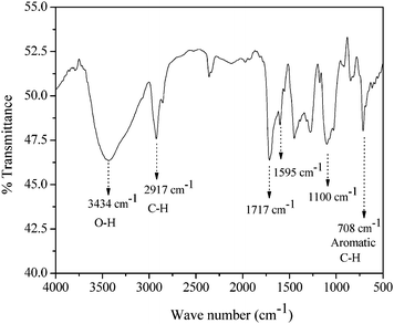 | ||
| Fig. 1 FTIR spectrum of BPVA-PVAcopolymer. | ||
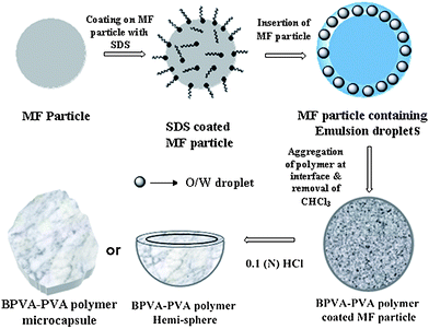 | ||
| Scheme 1 A schematic representation of the key steps associated with the fabrication of the complex polymer architecture. In the first step, surface positive charge of MF particle was suppressed with SDS surfactant. It was then inserted to O/W emulsion droplet having BPA-PVA polymer. Under vortexing, this polymer aggregated at interface of the droplet and followed by removal of chloroform polymer membrane collapsed on MF particle. Finally, removal of MF particle at 0.1 N HCl leads to adapt polymer membrane with different complex architectures. | ||
Coating of SDS molecules on the surface of MF particles has been confirmed with zeta potential measurements as shown in Fig. 2a, where bare MF particle has +50.7 mV surface potential but after adsorption of SDS molecules on the surface of this particle, surface potential is reduced to 10.3 mV. This change in zeta potential value suggests that adsorption of SDS occurs on MF particles and this potential value plays a key role in forming a stabilized emulsion droplet on the MF particle. We have performed a series of experiments and found that stabilized emulsion droplets on MF particles can only appear around this surface potential value. This surface potential of MF particle is optimized by varying the incubation time with SDS as shown in the ESI (Fig. S2†). This change in surface potential helps to attract emulsion droplets towards the MF particles, as surface of the emulsion droplets are negatively charged due to presence of SDS molecules.
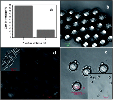 | ||
| Fig. 2 Shielding the surface positive charge of MF particles and insertion to emulsion droplet. The zeta potential of bare MF particles (n = 0) in (a) decreased from +53.5 mV to +13 mV on treatment with SDS surfactant (n = 1). (b) The bright field image shows that O/W emulsion droplets are around the MF (colloidal) particle and thus a ‘templated emulsion’ has been formed (scale bar is 2 μm). (c) MF particles inside the O/W droplet with BPVA-PVA polymer (inset scale bar is 10 µm) and (d) shows short range ordering of coated MF particles on air drying (scale bar is 5 µm). | ||
To prove the concept of insertion of MF particles inside O/W emulsion droplets, we have further carried out a simple experiment where MF particles were taken in 1 ml SDS-water solution for masking the surface potential (55.3 mV) of particles with SDS and then followed by adding chloroform into mixture, we observed that O/W droplets are stacked on the surface of MF particle as shown in bright field image of Fig. 2b.
Arrangement of these O/W droplets around MF particles for different Z distance has been shown in the ESI (Fig. S1†). As these emulsion droplets contain MF particles (colloidal templates) inside the core, we called these emulsion as “templated emulsion” that is emulsion droplets are around colloidal template (MF) particle. Thickness of emulsion layer on MF particle is 1.92 ± 0.07 μm.
Coating on MF particles
Similar experiments were carried out in the presence of copolymer (BPVA-PVA). Encapsulation of MF particles inside emulsion droplets was achieved in the presence of polymer in chloroform, and that gives rise to uniform coating of polymer around the template (MF particle) under vortexing. As these droplets (with MF particles inside the droplets) are made up of BPVA-PVApolymers, upon vortexing they undergo diffusion from chloroform media and aggregate at the interface (chloroform–water) of the emulsion droplet and form a polymer coating (membrane) at the interface. As a consequence uniform coating of polymer takes place around the MF particle as shown in Fig. 2c. On drying these coated MF particles are packed in a short range arrangement as shown in Fig. 2d. After removal of chloroform, this polymer membrane collapsed on MF particle and that has been examined with FESEM as shown in Fig. 3.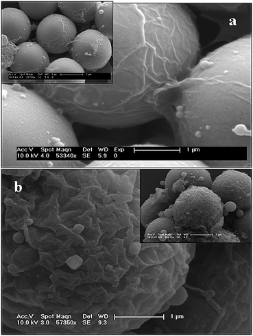 | ||
| Fig. 3 Coated MF particles after the removal of chloroform at 55 °C. (a) and (b) are folded polymer membranes on the MF particles after 15 min and 60 min vortexing treatment respectively. | ||
The folded polymer membrane on the MF particle clearly supports the insertion of the MF particle followed by aggregation of BPVA-PVApolymer upon emulsion. Depending on the vortexing duration, we can tune the thickness of the membrane and that is one of the key steps in obtaining complex morphology of polymer assembly. For example, on 20 min vortexing, aggregation of BPVA-PVA is sufficient to give a thin polymer coating (shown in Fig. 3a) on MF particle and that leads to conventional microcapsules upon chemical etching of MF particle at 0.1 N HCl and if we allow this reaction mixture to undergo vortexing for 1 h it will form thick membrane on the MF particle as shown in Fig. 3b and that will give rise to hemispheres.
Complex architecture of polymer
In this work, we have selected PVA as a native polymer component due to its biocompatible properties.36Benzoylation of PVA polymer has been achieved to induce hydrophobicity on the polymer backbone and enhance the solubility of BPVA-PVA in organic solvents. After successful coating of BPVA-PVArandom copolymer on MF particle, we dissolved the MF particle through chemical etching in 0.1 N HCl media.37,38 There are various reports in literature for removing template by external force and its effect on morphology. For example, Karman and Tsien39 described the buckling of spherical shells by external pressure. They explained that beyond some critical pressure, a hollow sphere no longer remains as a uniformly contracted sphere, it suddenly buckles with finite displacements into a non-spherical shape. After that, nonlinear and linear theories of bending and buckling of shell of hollow spheres have been proposed to explain the phenomena more clearly.40,41 In our system, dissolution or disintegration of MF particles at 0.1 N HCl is a very fast process as reported in the literature.37 Fast removal of MF particles creates a sudden void around the polymer membrane or more precisely inside the nascent hollow polymer sphere shell and that leads to generate high pressure on polymer shell and as a consequence it adopt different kinds of morphology depending on the thickness of this polymer membrane. In principle, we can compare this phenomenon with leaking of a football. Depending on the size of the pore of the leaking point as well as thickness of the shell it prefers to adapt different shapes. Fig. 4a, b and c also demonstrate the same phenomenon. So, by controlling the vortexing duration we can tune the thickness of the polymer membrane on a MF particle and after dissolution of the MF particle it prefers to have a different shape. Along with the BPVA-PVAmembrane on the MF particles some colloidal particles of BPVA-PVA polymers are also formed in the reaction as shown in Fig. 4c. Some free emulsion droplets in solution are responsible for this colloidal particle formation. At the end of the process we have separated these colloidal particles simply by centrifugation.42 Volume of this BPVA-PVApolymer hemisphere is around 5.75 femtolitre and such materials find extensive application in chemical, biological and materials science.1–4
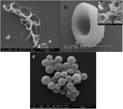 | ||
| Fig. 4 The different morphologies of BPVA-PVApolymer membrane on dissolving the MF particles (a) and (b) are images of hollow capsules and hemispheres respectively. (c) Microspheres of BPVA-PVApolymer. | ||
Effect of vortexing
Thus, following this simple approach we can access wide variety of complex architectures of polymer materials as shown in Fig. 4a, b and c. We have also shown the different architectures of polymer assemblies such as rigid microcapsules, collapsed spheres and distorted hemispheres based on changing the duration of vortexing as shown in Fig. 5. After 90 min vortex treatment, it appeared as hollow sphere of polymer on removal of colloidal template.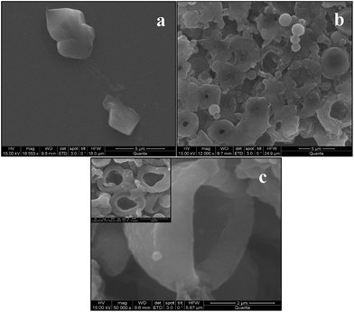 | ||
| Fig. 5 Different morphologies of BPVA-PVApolymer membrane on dissolving the MF particle depending on vortexing duration. (a) Image of rigid capsules or capsules with thick membrane. (b) Hollow distorted spheres with pores on the surface and (c) distorted hemispheres. | ||
Along with core dissolution, shell thickness also plays key role for fabrication of bowls/cups from inorganic materials as reported in the literature.43,44 In our present study we have also noticed that the thickness of the polymer membrane plays a significant role to adapt a particular shape on dissolution of the sacrificial core. In Table 1, we have accounted for the relationship between duration of vortex, membrane thickness, and exterior surface area of coated polymer membrane on MF particle and polymer architecture. With increasing the duration of vortexing, the thickness of the polymer membrane and surface area of the polymer membrane increase which guides the formation of the different architectures of the polymer assembly.
| Duration of vortexing | Membrane thickness | Surface area of the membrane | Architecture of the polymer assembly |
|---|---|---|---|
| 20 min | 17 ± 2 nm | 39.23 μm2 | Flexible capsule |
| 25 min | 28 ± 3 nm | 39.72 μm2 | Rigid capsule |
| 30 min | 145 ± 5 nm | 45.12 μm2 | Collapse sphere |
| 45 min | 470 ± 7 nm | 61.92 μm2 | Distorted hemisphere |
| 60 min | 675 ± 10 nm | 73.89 μm2 | Hemisphere |
| 90 min | 890 ± 10 nm | 87.58 μm2 | Hollow sphere |
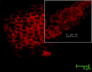 | ||
| Fig. 6 3D CLSM image of Rhodamine-B loaded BPVA-PVApolymer hemisphere. | ||
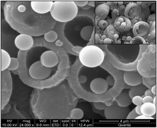 | ||
| Fig. 7 BPVA-PVA polymer hemisphere loaded with colloidal particles. These colloidal particles are formed during the deposition of polymer on MF particles. | ||
This can be further explored to prepare polymer nanocomposite or hybrid structures of inorganic and organic materials. In the present report we have mainly focused on PVA based random copolymer (BPVA-PVA), we believe similar approach is applicable to wide range of polymers.
The MF core was dissolved by adding 0.1 N HCl solution and allowed to dry in air. We have observed predominantly honeycomb structures of BPVA-PVA as shown in Fig. 8. Although we have arranged these hemispheres in honeycomb fashion, this arrangement is not spread over a long range. Now, we are trying to obtain long range honeycomb arrangements by controlling the recipe of emulsion.
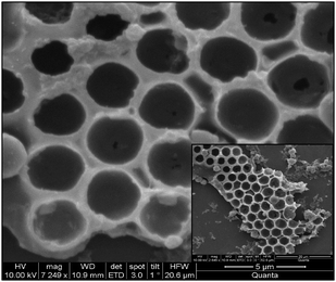 | ||
| Fig. 8 Honeycomb arrangement of the hemispheres; BPVA-PVA coated particles are drop cast on silicon wafer. After proper drying the coated particle assembly, MF particles are dissolved with 0.1 N HCl solutions and thus honeycomb arrangement of the hemispheres were observed. | ||
Conclusion
In conclusion, the present study reports a versatile and robust approach for the fabrication of wide range of exotic structures of nonionic copolymer such as hemispheres and hollow microcapsules by emulsion method. The polymer may undergo different structures depending upon the duration of vortexing. We have also demonstrated the possible applications of these exotic structures. In particular these soft materials containers were employed to load submicron colloidal particles as well as functional organic dyes. This flexibility of application in biology and materials science allows a wide range of prospects to be explored.Acknowledgements
The authors would like to thank Nano centre and Mr Sumanta Mukherjee for assistance with FESEM measurements.References
- H. Song and R. F. Ismagilov, J. Am. Chem. Soc., 2003, 125, 14613 CrossRef CAS.
- Y. Rondelez, G. Tresset, K. V. Tabata, H. Arata, H. Fujita, S. Takeuchi and H. Noji, Nat. Biotechnol., 2005, 23, 361 CrossRef CAS.
- A. Hatch, A. E. Kamholz, K. R. Hawkins, M. S. Munson, E. A. Schilling, B. H. Weigl and P. Yager, Nat. Biotechnol., 2001, 23, 461 CrossRef.
- E. Ostuni, C. S. Chen, D. E. Ingber and G. M. Whitesides, Langmuir, 2001, 17, 2828 CrossRef CAS.
- Y. Yeo, E. Bellas, W. Firestone, R. Langer and D. S. Kohane, J. Agric. Food Chem., 2005, 53, 7518–7525 CrossRef CAS.
- S. H. Im, U. Jeong and Y. Xia, Nat. Mater., 2005, 4, 671 CrossRef.
- K. S. Krishna, U. Mansoori, N. R. Selvi and M. Eswaramoorthy, Angew. Chem., Int. Ed., 2007, 46, 5962 CrossRef CAS.
- X. Li, J. Peng, J. H. Kang, J. H. Choy, M. Steinhart, W. Knoll and D. H. Kim, Soft Matter, 2008, 4, 515 RSC.
- D. Jagadeesan, U. Mansoori, P. Mandal, A. Sundaresan and M. Eswaramoorthy, Angew. Chem., Int. Ed., 2008, 47, 7685 CrossRef CAS.
- N. S. John, N. R. Selvi, M. Mathur, R. Govindarajan and G. U. Kulkarni, J. Phys. Chem. B, 2006, 110, 22975 CrossRef CAS.
- J. C. Love, B. D. Gates, D. B. Wolfe, K. E. Paul and G. M. Whitesides, Nano Lett., 2002, 2, 89.
- D. E. Bergbreiter, Angew. Chem., Int. Ed., 1999, 38, 1870 CrossRef CAS.
- D. Lee, M. F. Rubner and R. E. Cohen, Chem. Mater., 2005, 17, 1099 CrossRef CAS.
- Z. Tang, Y. Wang, P. Podsiadlo, N. A. Kotov and A. N. Zelikin, Adv. Mater., 2006, 18, 3203 CrossRef CAS.
- O. Kreft, M. Prevot, H. Mohwald and G. B. Sukhorukov, Angew. Chem., Int. Ed., 2007, 46, 5605 CrossRef.
- M. Fujiwara, K. Shiokawa, Y. Tanaka and Y. Nakahara, Chem. Mater., 2004, 16, 5420 CrossRef CAS.
- U. Manna and S. Patil, J. Phys. Chem. B, 2008, 112, 13258 CrossRef CAS.
- F. Caruso, D. Trau, H. Mohwald and R. Renneberg, Langmuir, 2000, 16, 1485 CrossRef CAS.
- G. Decher, Science, 1997, 277, 1232 CrossRef CAS.
- G. Decher and J. D. Hong, Makromol. Chem. Macromol. Symp., 1991, 46, 321 Search PubMed.
- G. Decher, M. Eckle, J. Schmitt and B. Struth, Curr. Opin. Colloid Interface Sci., 1998, 3, 32 CAS.
- F. Caruso, R. A. Caruso and H. Mohwald, Science, 1998, 282, 1111 CrossRef CAS.
- G. B. Sukhorukov, E. Donath, H. Lichtenfeld, E. Knippel, M. Knippel and H. Mohwald, Colloids Surf., A, 1998, 137, 253 CrossRef.
- F. Caruso, H. Lichtenfeld, M. Giersig and H. Mohwald, J. Am. Chem. Soc., 1998, 120, 8523 CrossRef CAS.
- F. Caruso, E. Donath and H. Mohwald, J. Phys. Chem. B, 1998, 102, 2011 CrossRef CAS.
- Y. Zhang, S. Yang, Y. Guan, W. Cao and J. Xu, Macromolecules, 2003, 36, 4238 CrossRef CAS.
- U. Manna and S. Patil, Biomacromolecules, 2009, 10, 2632 CrossRef CAS.
- U. Manna and S. Patil, J. Phys. Chem. B, 2009, 113, 9137 CrossRef CAS.
- A. Postma, Y. Yan, Y. Wang, A. N. Zelikin, E. Tjipto and F. Caruso, Chem. Mater., 2009, 21, 3042 CrossRef CAS.
- O. D. Velev, K. Furusawa and K. Nagayama, Langmuir, 1996, 12, 2374 CrossRef CAS.
- O. D. Velev and K. Nagayama, Langmuir, 1997, 13, 1856 CrossRef CAS.
- A. D. Dinsmore, M. F. Hsu, M. G. Nikolaides, M. Marquez, A. R. Bausch and D. A. Weitz, Science, 2002, 298, 1006 CrossRef CAS.
- O. D. Velev, K. Furusawa and K. Nagayama, Langmuir, 1996, 12, 2385 CrossRef CAS.
- P. F. Noble, O. J. Cayre, R. G. Alargova, O. D. Velev and V. N. Paunov, J. Am. Chem. Soc., 2004, 126, 8092 CrossRef CAS.
- V. Cimenez, A. Mantecon and V. Cadiz, J. Polym. Sci., Part A: Polym. Chem., 1996, 34, 925 CrossRef.
- Y. Ikada, H. Iwata, F. Horii, T. Matsunaga, M. Taniguchi, M. Suzuki, W. Taki, S. Yamagata, Y. Yonekawa and H. Handa, J. Biomed. Mater. Res., 1981, 15, 697 CrossRef CAS.
- C. S. Peyratout and L. Dahne, Angew. Chem., Int. Ed., 2004, 43, 3762 CrossRef.
- U. Manna and S. Patil, Langmuir, 2009, 25, 10515 CrossRef CAS.
- T. Karman and H. S. Tsien, J. Aero. Sci., 1939, 7, 43 Search PubMed.
- S. Timoshenko, Theory of Elastic Stability, McGraw-Hill, New York, 1936 Search PubMed.
- E. L. Reiss, H. J. Greenberg and H. B. Keller, J. Aero. Sci., 1957, 24, 533 Search PubMed.
- P. H. Brown and P. Schuck, Biophys. J., 2006, 90, 4651 CrossRef CAS.
- I. Noda, T. Kamoto, Y. Sasaki and M. Yamada, Chem. Mater., 1999, 11, 3693 CrossRef CAS.
- I. Noda, T. Kamoto and M. Yamada, Chem. Mater., 2000, 12, 1708 CrossRef CAS.
- Y. Xia, Y. Yin, Y. Lu and J. Mclellan, Adv. Funct. Mater., 2003, 13, 907 CrossRef CAS.
Footnote |
| † Electronic supplementary information (ESI) available: The arrangement of O/W droplets around MF particles for different Z distances and the variation of zeta potential of MF particles with time of incubation with SDS. See DOI: 10.1039/c0jm01106a |
| This journal is © The Royal Society of Chemistry 2011 |
