Highly active ZnxCd1−xS photocatalysts containing earth abundant elements only for H2 production from water under visible light†
Yabo
Wang
a,
Jianchun
Wu
a,
Jianwei
Zheng
b and
Rong
Xu
*a
aSchool of Chemical & Biomedical Engineering, Nanyang Technological University, 62 Nanyang Drive, Singapore 637459. E-mail: rxu@ntu.edu.sg; Fax: +65 67947553; Tel: +65 67906713
bInstitute of High Performance Computing, 1 Fusionopolis Way, #16-16 Connexis, Singapore 1, 38632
First published on 5th July 2011
Abstract
A series of ZnxCd1−xS photocatalysts were synthesized via a solvothermal method using ethylenediamine (EDA) as the solvent. The structural, optical and morphological properties have been investigated extensively by various analytical techniques. It has been found that ZnxCd1−xS (x ≤ 0.5 in the precursor) nanorods and nanoparticles can be formed as good homogeneous solid solutions. During the synthesis process, EDA played an important dual role as the solvent and the coordinating agent, which contributed to the formation of nanosized ZnxCd1−xS solid solutions. Efficient hydrogen production from the aqueous solution containing S2− and SO32− sacrificial reagents was observed over these photocatalysts under visible light irradiation (λ ≥ 420 nm) in the absence of any expensive metal components and co-catalysts. The highest photocatalytic activity for hydrogen production was obtained over Zn0.5Cd0.5S with a rate of 1097 μmol h−1 and the corresponding quantum efficiency of 30.4% at 420 nm. These values are much higher than those previously reported for Zn–Cd binary sulfide photocatalysts. The excellent photocatalytic performance can be attributed to the efficient visible light absorption and the suitable band structure due to the formation of solid solutions.
Introduction
Hydrogen has been considered as the next generation energy carrier due to its advantageous features such as non-toxicity, zero emission upon combustion, high specific energy value, etc.1 Since the first report on using the TiO2 photocatalyst to split water under UV light in early 1970s,2 many research groups have committed to the development of efficient photocatalysts for hydrogen production by using solar energy. To date, over one hundred types of inorganic materials systems have been reported to be capable for hydrogen production by photocatalytic water splitting.3–5 To better utilize the solar light which is composed of about 45% of visible light and only 4% of UV light, there is still a great need for the development of visible light responsive photocatalysts with high activities and good stabilities.6,7 So far, several promising photocatalyst systems with good efficiencies under visible light have been reported, such as (i) metal sulfide solid solutions such as Ru/ZnS–CuInS2–AgInS2,8 ZnS–In2S3–Ag2S,9 and Pt–PdS/CdS10 in aqueous solutions containing sacrificial electron-donor reagents, (ii) rhodium and chromium oxides loaded (Ga1−xZnx)(N1−xOx) in pure water for overall water splitting,11 and (iii) Z-scheme catalysts consisting of Pt/ZrO2/TaON and Pt/WO3 in water containing the ionic redox IO3−/I− pair.12From the economic point of view, the abundance and cost of the elements in photocatalyst materials are important factors to be considered for potential large scale applications. Table S1 (ESI†) lists the abundance and price of some commonly employed metal elements in the photocatalysts for hydrogen production. Based on these data, it is evident that in order to develop low-cost photocatalysts, it is necessary to minimize or avoid the use of precious metals like Pt, Pd, Rh, etc. The use of the earth abundant elements like Zn, Ga, W, Cd, Cu and Ni would lead to affordable photocatalysts for practical use. Several types of low-cost photocatalysts based on the ternary metal sulfides of Zn, Cd and Cu, and nanocomposites of NiS and CdS have been reported recently by our group with good efficiencies.13–16
Compared with metal oxides, the valance band maximum of metal sulfides consisting of an S 3p orbital is located at higher energy levels, which usually leads to narrow band gaps with a visible light response.17,18 Among the metal sulfides investigated, CdS with a narrow band gap of 2.4 eV and a suitable band structure is one of the most frequently studied materials for hydrogen production from aqueous solution containing sacrificial reagents under visible light irradiation.10,16,19–23 However, the activity of CdS is normally very low and the use of noble metals or other semiconductor co-catalysts is crucial to achieve good activities. ZnS with a wide band gap (3.5 eV) is another widely investigated metal sulfide photocatalyst. Doping by foreign elements such as Cu2+ and Ni2+ can form discrete donor levels in the forbidden band of ZnS, resulting in the visible light response.24,25 Besides doping, the formation of solid solution is another promising approach which enables the visible light response of ZnS because of the shift of both valance band and conduction band positions. Several Zn-containing metal sulfide solid solutions involving Ag, Cu and In have been reported as promising solid solution photocatalysts.8,9,18,26–28 The solid solutions between ZnS and CdS have also been reported as efficient photocatalysts.13,29–34 However, the formation of solid solutions between ZnS and CdS is not very straightforward and sometimes the composites between the two were rather formed which led to compromised activities. Many groups adopted the high temperature annealing method to obtain such sulfide solid solutions.26–31
Herein, we reported a convenient and facile solvothermal method to prepare solid solutions of ZnS and CdS. The as-prepared low-cost photocatalysts display much higher activities for hydrogen production compared to those previously reported in the absence of any dopants and co-catalysts. The materials properties of the ZnxCd1−xS samples synthesized in this work were thoroughly investigated to reveal the structure–activity relationships.
Experimental
Synthesis of ZnxCd1−xS samples
All reagents were of analytical grade and used without any purification. Typically, a total of 5 mmol of the metal precursors of zinc acetate (Zn(Ac)2·2H2O, >99.0%, Alfa Aesar) and cadmium acetate (Cd(Ac)2·2H2O, >99.0%, Kanto Chemical) and 20 mmol of thioacetamide (TAA, 99%, Alfa Aesar) were added to 30 mL of ethylenediamine (EDA, >99.5%, Alfa Aesar). After vigorous stirring for 1 h, the resultant mixture was transferred to a 45 mL PTFE-lined stainless steel autoclave and kept at 180 °C for 24 h followed by cooling to room temperature naturally. The resultant precipitate was centrifuged and washed thoroughly with ethanol and de-ionized water for several times. To avoid any possible oxidation of the as-prepared metal sulfides and particle aggregation, a fraction of the product was kept wet in an aqueous solution of 0.1 M sodium sulfide (Na2S·9H2O, extra pure, Acros Organics) for photocatalytic water splitting reaction. The concentration of the metal sulfide solid in the aqueous solution was about 25 mg mL−1. The other portion of the product was dried at 60 °C overnight for materials characterization. For comparison, the sample prepared with the Cd![[thin space (1/6-em)]](https://www.rsc.org/images/entities/char_2009.gif) :Zn molar ratio of 50:50 after being aged in Na2S solution for 24 h was collected and dried at 60 °C overnight for characterization. The effects of the Zn:Cd ratio and the reaction time were investigated and the detailed experimental conditions are listed in Table 1.
:Zn molar ratio of 50:50 after being aged in Na2S solution for 24 h was collected and dried at 60 °C overnight for characterization. The effects of the Zn:Cd ratio and the reaction time were investigated and the detailed experimental conditions are listed in Table 1.
| x value | Atomic ratio of Zn2+:Cd2+ |
Band gapc/eV | BET surface area/m2 g−1 | H2 production rated/μmol h−1 | Synthesis conditions | |
|---|---|---|---|---|---|---|
| In precursora | Overall compositionb | |||||
| a Calculated on the basis of metal precursors used. b Calculated from ICP-AES results. c Calculated on the basis of the onset of the absorbance from UV-Vis DRS. d Average production rate over 5 h of reaction time. e Pure ZnS sample synthesized using water as the solvent. | ||||||
| 0 | 0:100 |
0:100 |
2.34 | 15.2 | 17 | 180 °C, 24 h |
| 0.3 | 30:70 |
23.2:76.8 |
2.43 | 18.1 | 801 | 180 °C, 24 h |
| 0.4 | 40:60 |
35.2:64.8 |
2.45 | 26.1 | 874 | 180 °C, 24 h |
| 0.5 | 50:50 |
42.3:57.7 |
2.46 | 27.2 | 1097 | 180 °C, 24 h |
| 0.6 | 60:40 |
50.2:49.8 |
2.47 | 24.2 | 1012 | 180 °C, 24 h |
| 0.7 | 70:30 |
64.9:35.1 |
2.48 | 17.9 | 627 | 180 °C, 24 h |
| 0.8 | 80:20 |
78.2:21.8 |
2.49 | 10.3 | 263 | 180 °C, 24 h |
| 1.0e | 100:0 |
100:0 |
3.39 | 5.8 | 0 | 180 °C, 24 h |
| 0.5 | 50:50 |
49.6:50.4 |
2.46 | 48.2 | 567 | 180 °C, 2 h |
| 0.5 | 50:50 |
43.4:56.6 |
2.45 | 41.5 | 868 | 180 °C, 6 h |
| 0.5 | 50:50 |
42.9:57.1 |
2.44 | 29.3 | 893 | 180 °C, 12 h |
| 0.5 | 50:50 |
41.9:58.1 |
2.43 | 24.3 | 865 | 180 °C, 48 h |
Characterization
The X-ray diffraction (XRD) patterns of the as-prepared samples were obtained on a X-ray diffractometer (Bruker AXS D8, Cu Kα, λ = 1.5406 Å, 40 kV and 20 mA) in the range of 10°–80° with a step size of 0.02° s−1. A UV-visible spectrophotometer (UV-2450, Shimadzu) was used to record the UV-visible diffuse reflectance spectra (UV-vis DRS). Fourier transformed infrared (FTIR) spectra were obtained on a FTIR spectrometer (spectrum one, Perkin Elmer) with a 4 cm−1 resolution in the range of 450–4000 cm−1 using a standard KBr pellet technique. The morphologies of samples were observed on a field emission scanning electron microscope (FESEM, JEOL JSM 6700F) equipped with an energy dispersive spectroscope (EDS) and transmission electron microscope (TEM, JEOL 3010). Elemental maps were obtained by energy-filtered TEM analysis performed on TEM (JEOL 3010) equipped with a Gatan imaging filter. The metal compositions were determined using inductively coupled plasma atomic emission spectroscopy (ICP-AES) on a Perkin Elmer ICP Optima 2000DV machine. X-Ray photoelectron spectroscopy (XPS) analysis was conducted on an Axis Ultra spectrometer (Kratos Analytical) using a monochromated Al Kα X-ray source (1486.7 eV) operating at 15 kV. Nitrogen adsorption–desorption measurement was conducted at 77.35 K on a Quantachrome Autosorb-6B apparatus to measure the Brunauer–Emmett–Teller (BET) surface area. The percentage of carbon was measured in an Elementarvario CHNS elemental analyzer.Evaluation of photocatalytic activity
Visible light-driven photocatalytic water splitting reaction was conducted in a top window Pyrex cell connected to a closed gas circulation and evacuation system. In a typical run, a certain volume of the catalyst suspension containing 0.1 g of the catalyst was well dispersed with constant stirring in 100 mL of the aqueous solution containing 0.7 M sodium sulfide (Na2S·9H2O, extra pure, Acros Organics) and 0.5 M sodium sulfite (Na2SO3, 98%, Alfa Aesar). Before the reaction, the system was evacuated and refilled with argon gas for several times to remove the air and finally filled with argon of approximately 30 torr. A 300 W Xenon lamp equipped with a cut-off filter (λ ≥ 420 nm) was used to provide incident visible light. The temperature of the photoreaction cell was kept at 18–21 °C by the cooling water. The produced hydrogen gas was analyzed by online gas chromatography (Agilent 6890N, TCD detector, argon as carrier gas, 5 Å molecular sieve column). The apparent quantum efficiency (QE) was measured under the same reaction conditions equipped with a band pass interference filter (Newport, center wavelength 420 nm, band width 10 nm). The number of photons from the radiation source was measured using a silicon photodiode (13 DAS 005, MELLES GRIOT) connected to a broadband power/energy meter (13 PEM 001, MELLES GRIOT). Eqn (1) was used for the calculation of quantum efficiency. | (1) |
Results and discussion
Formation of ZnxCd1−xS solid solutions
A series of ZnxCd1−xS samples (where x = 0, 0.3, 0.4, 0.5, 0.6, 0.7, 0.8 and 1.0 in the precursor solutions) were obtained via a solvothermal method using EDA as the solvent. The XRD patterns of the as-prepared samples synthesized at 180 °C with a reaction time of 24 h are displayed in Fig. 1. As shown in Fig. 1a-A, the XRD peaks of the sample with Cd2+ alone (x = 0) can be indexed to a hexagonal wurtzite phase of CdS (JCPDS card No. 75-1545). With the increase of x value to 0.3–0.6, the diffraction intensities become relatively weaker. Due to the smaller ionic radius, Zn2+ (0.74 Å) can be incorporated into the lattice of CdS or enter its interstitial sites.30 Compared with the pure CdS sample, the lower crystallinity of the ZnxCd1−xS samples can be ascribed to the disorder or distortion of the crystal structure caused by the incorporation of Zn2+ ions into the lattice of CdS.35,36 A successive shift to higher diffraction angles can be observed for both (100) and (002) peaks in Fig. 1b (curves A–E) due to the formation of ZnxCd1−xS solid solutions.29,30,32 However, the peak at the (101) position appears more complicated. In the sample with x at 0.3 (Fig. 1b–B), it is observed at a higher angle compared with that of CdS. When x is increased to 0.4 and 0.5 (Fig. 1b–C and D), this peak becomes weaker and broader. However, when x is at 0.6, the peak turns stronger and the position is shifted back to the lower angle. Based on the trend observed for samples with x at 0.6, 0.7 and 0.8 (Fig. 1b-E–G), cubic phased ZnS (JCPDS card No. 05-0566) starts to form in the sample with x at 0.6 as evidenced by the increasing intensity of the (111) peak. Hence, a composite system composed of solid solution of ZnxCd1−xS and ZnS is formed in samples with x greater than or equal to 0.6. In fact, in the sample with x at 0.8, cubic ZnS becomes the dominant phase as shown in Fig. 1-G. Finally with Zn2+ alone (x = 1.0), the ZnS·(EDA)0.5 complex was obtained (Fig. 1a-H) because of the strong coordination ability of EDA to Zn2+ ions.37 The weight percentage of carbon in this sample is 9.9% which agrees well with this composition. The FTIR spectrum shown in Fig. S1a (ESI†) also confirms the existence of EDA. Thus, for comparison purpose, a pure ZnS sample was synthesized using water as the solvent while keeping other synthesis conditions the same. Fig. 1a-I indicates that the thus obtained ZnS has a cubic phase.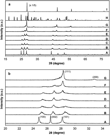 | ||
| Fig. 1 (a) Wide range and (b) narrow range XRD patterns of as-prepared ZnxCd1−xS samples by the solvothermal method (180 °C, 24 h). The values of x: (A) 0, (B) 0.3, (C) 0.4, (D) 0.5, (E) 0.6, (F) 0.7, (G) 0.8, (H) 1.0; (I) pure ZnS sample synthesized using water as the solvent (180 °C, 24 h). | ||
Fig. 2 shows the UV-vis DRS results of ZnxCd1−xS samples and the pure ZnS sample. All spectra show intense absorption bands with a steep absorption edge. Similar absorption spectra can be found in literatures for ZnxCd1−xS solid solutions.13,29,30,32 It can be observed that with the increase of Zn2+ percentage, the absorption edges of the samples display a gradual blue shift with their band gaps increasing from 2.34 eV (CdS) to 2.49 eV (x = 0.8). The band gap energies of the binary Zn–Cd sulfide samples estimated from the onset of the absorption edge are in a close range of 2.43–2.49 eV as listed in Table 1. Hence, they all have visible light absorption ability. To provide further evidences on the formation of solid solutions in samples with 0.3 ≤ x ≤ 0.5, the first derivatives of the UV-vis DRS curves are shown in Fig. S2 (ESI†). The corresponding first derivative curves of both CdS (x = 0) and ZnS spectra exhibit a symmetric peak as expected for these two pure samples. Although the peaks are broader for samples with 0.3 ≤ x ≤ 0.5, they still appear fairly symmetric, indicating a good homogeneity in the composition. Consistent with this, the elemental mappings of Cd, Zn and S in sample Zn0.5Cd0.5S (Fig. 3) show an even distribution of all the elements, which is distinctively different from our previous observation on the Zn–Cd–Cu–S nanocomposite photocatalyst.15 However, when x is increased to 0.6–0.8, the peaks become more and more non-symmetric (Fig. S2, ESI†). Such an observation is in agreement with the formation of the secondary ZnS phase in these samples as earlier shown in the XRD results.
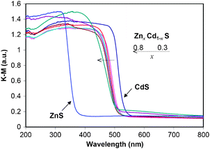 | ||
| Fig. 2 UV-visible diffuse reflectance spectra of as-prepared ZnxCd1−xS (0 ≤ x ≤ 0.8) samples by the solvothermal method (180 °C, 24 h) and pure ZnS sample. | ||
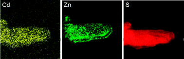 | ||
| Fig. 3 Energy filtered TEM elemental mapping images of sample Zn0.5Cd0.5S synthesized at 180 °C for 24 h. | ||
Although the formation of solid solutions between CdS and ZnS does not always occur according to literatures and our previous studies,14,15,33 in this work, a series of solid solutions of ZnxCd1−xS (x ≤ 0.5) were obtained through the solvothermal method. EDA is a kind of polydentate ligand which can coordinate with many metal cations. Hence EDA plays an important dual role as the solvent and the coordinating agent. During the synthesis, EDA can coordinate with Cd2+ and Zn2+ ions to form [Cd(EDA)n]2+ and [Zn(EDA)n]2+ complexes.38,39 With the increasing temperature, TAA decomposed gradually and released S2− ions. Finally, [Cd(EDA)n]2+ and [Zn(EDA)n]2+ complexes reacted with S2− and evolved to ZnxCd1−xS solid solutions.
The samples used for the above materials characterization were obtained by drying the freshly prepared products directly after the synthesis. Since the samples used for photocatalytic reactions were kept in the Na2S solution to avoid oxidation and aggregation, there exists the possibility that the aged samples may present different properties to those of the directly dried samples. Hence, the XRD and UV-vis DRS results for the two Zn0.5Cd0.5S samples which were dried directly and aged in Na2S solution for 24 h before drying, respectively, were obtained for comparison. As shown in Fig. S3 (ESI†), there is no distinct difference in both crystallographic and absorption properties between the two samples. Thus, the present characterization results obtained from the directly dried samples should represent the general properties of the aged samples.
Morphological evolution
Fig. 4 displays the FESEM images of the as-prepared ZnxCd1−xS samples. As EDA promotes the growth of CdS along the c-axis,22,39 the CdS sample obtained in this work similarly exhibits a nanorod morphology with an average length of 300 nm and a diameter of 90 nm (Fig. 4a). After the incorporation of Zn2+ ions, the preferential growth along the c-axis direction is retarded since EDA also promotes the growth of ZnS along the direction of the x–y plane.37,38 As a result, the length of the nanorods becomes shorter and the morphology turns less rod-like but more plate-like with increasing the Zn2+ percentage (Fig. 4b–e). When the Zn2+ content in the precursor solutions was further increased to 0.7 and 0.8 (the value of x), only microspheres composed of small particles and nanoplates were obtained (Fig. 4f and g). Finally, in the absence of Cd2+ ions, the formed ZnS·(EDA)0.5 complex exhibits a plate-like morphology as shown in Fig. 4h. The pure ZnS sample synthesized in H2O appears as irregularly shaped particles with their sizes in a range of 100–500 nm (Fig. 4i). The TEM image shown in Fig. 5a indicates that both nanorods and nanoparticles exist in sample Zn0.5Cd0.5S which is in good agreement with FESEM results. A typical HRTEM image shown in Fig. 5b displays the lattice fringes clearly, which is an indication of the good crystallinity of this sample. The measured lattice spacing of 3.54 Å is in good agreement with the interplanar distance of the [100] plane (3.53 Å) obtained from the XRD result. As such, the EDA-mediated growth pathway leads to the formation of nanosized crystals of ZnxCd1−xS solid solutions when the relative zinc content in the precursor is not greater than about 0.5 (x value). The specific surface areas were obtained by a nitrogen adsorption method and are listed in Table 1. It is obvious that the surface area is related to the morphological properties of the samples. Sample CdS with a nanorod morphology exhibits a relatively lower surface area of 15.2 m2 g−1. With an increasing Zn2+ content in the sample, the surface area becomes higher and the highest surface area obtained is 27.2 m2 g−1 (x = 0.5) due to the formation of small nanoparticles. Further increasing of the Zn2+ content leads to the formation of large microspheres (Fig. 4f and g) with lower surface areas. It is believed that a higher surface area is favorable for the enhancement of photocatalytic activity.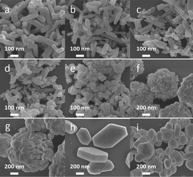 | ||
| Fig. 4 FESEM images of as-prepared ZnxCd1−xS samples by the solvothermal method (180 °C, 24 h). The values of x: (a) 0, (b) 0.3, (c) 0.4, (d) 0.5, (e) 0.6, (f) 0.7, (g) 0.8, (h) 1.0; (i) pure ZnS sample. | ||
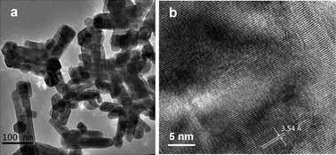 | ||
| Fig. 5 (a) TEM and (b) HRTEM images of sample Zn0.5Cd0.5S synthesized at 180 °C for 24 h. | ||
To gain more insights about the growth mechanism of the ZnxCd1−xS solid solutions, samples with x fixed at 0.5 were synthesized with different reaction durations. Fig. 6 displays the SEM images of these samples. At a short reaction time of 2 h, both microplates and short nanorods are present (Fig. 6a). Correspondingly, the IR spectrum of this sample indicates the presence of EDA (Fig. S1b, ESI†) and the estimated molar ratio of EDA:S by the elemental analysis is approximately 0.2:1. The SEM images show that the amount of microplates becomes less at 6 h (Fig. 6b) and only nanorods can be observed at 12 h (Fig. 6c). As shown earlier, a longer reaction time of 24 h led to the formation of both nanoparticles and nanorods (Fig. 4d and 5a). When the reaction time was prolonged to 48 h, some elongated nanoplates appear which was possibly due to the aggregation of the nanorods (Fig. 6d).
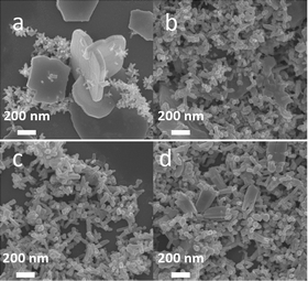 | ||
| Fig. 6 FESEM images of sample Zn0.5Cd0.5S synthesized with different reaction times, (a) 2 h, (b) 6 h, (c) 12 h, (d) 48 h. | ||
The coordination ability of EDA to Zn2+ ions (log β of Zn[EDA]32+ = 14.11) is stronger than that to Cd2+ ions (log β of Cd[EDA]32+ = 12.18).40 Thus, in the pure Zn system, EDA remains coordinated with Zn2+ ions as ZnS·(EDA)0.5 even at the reaction time of 24 h, while this does not occur for the pure Cd system as demonstrated in our XRD (Fig. 1), FTIR (Fig. S1, ESI†) and the elemental analysis results. In the case of the Zn–Cd binary system, the chemical process coupled with the morphological evolution can be described as follows. In the initial stage of the reaction, the plate-like particles corresponding to EDA-complexed products preferentially form because of the strong coordination ability of EDA with Zn2+ ions. The XRD pattern shown in Fig. S4a (ESI†) indicates that besides ZnxCd1−xS, ZnyCd1−yS(EDA)0.5 complexes may also exist at this stage. The latter is supported by the EDS analysis result shown in Fig. S5 (ESI†) which indicates that both Zn and Cd are present in the plate-like area with a molar ratio of Zn:Cd at about 1.5:1. The ICP results (Table 1) show that this sample has almost the same metal composition as that in the precursor solution (50:50). At longer reaction time, the complexes decompose, leading to the collapse of the plate-like structure and the formation of nanorods and nanoparticles. Furthermore, the molar ratio of Zn2+:Cd2+ decreases and stabilizes at around 42:58 because of a smaller thermodynamic solubility product of CdS compared to that of ZnS.41 A similar phenomenon is found in ZnxCd1−xS with other compositions as shown in Table 1.
Photocatalytic activities
Photocatalytic hydrogen production from the aqueous solution containing Na2S and Na2SO3 as sacrificial reagents was conducted under visible light using a 300 W Xenon lamp equipped with a cutoff filter (λ ≥ 420 nm). The average hydrogen production rate and the time course of hydrogen production over different samples were shown in Table 1 and Fig. 7, respectively. No hydrogen gas was produced when the pure ZnS sample was used as the photocatalyst as this wide band gaped sample (Eg = 3.39 eV) only absorbs UV light. The sample CdS showed a low activity of 17 μmol h−1. After the incorporation of Zn2+ ions, the activities for hydrogen production increased dramatically. The hydrogen production rate obtained over the sample Zn0.3Cd0.7S was as high as 801 μmol h−1 and further increased to 1097 μmol h−1 over sample Zn0.5Cd0.5S, which is about 64 times higher than that over CdS alone. The apparent quantum efficiency of sample Zn0.5Cd0.5S was measured to be 30.4% at 420 nm. Such photocatalytic activities are much better than those reported previously (hydrogen production rate <350 μmol h−1, quantum efficiency <15%) over Zn–Cd binary sulfides prepared by various methods.30–32,34 With further increase of the Zn2+ content, the activity dropped due to the formation of the ZnS phase in the products. Nevertheless, the hydrogen production rate obtained over Zn0.6Cd0.4S was still as high as 1012 μmol h−1 since only a small percentage of ZnS is present in this sample. However, when more Zn2+ was incorporated, the activity dropped quickly. In particular, the hydrogen production rate obtained over sample Zn0.8Cd0.2S was only 263 μmol h−1. The ZnS phase present as well as the morphology of microsphere-like aggregates (Fig. 4f and g) leads to unfavorable light absorption and charge transfer. As shown earlier, sample Zn0.5Cd0.5S possesses the highest surface area, which should be another reason for its high activity. Table 1 also presents the hydrogen production rates over samples Zn0.5Cd0.5S synthesized at different reaction times. The low activity of 567 μmol h−1 over the sample synthesized at 2 h is well expected due to the incomplete conversion of the metal complexes to sulfide solid solution as discussed. Further prolonging the reaction time promoted the formation of solid solutions as well as improved the crystallinity, leading to the increased photocatalytic activities. The hydrogen production rate obtained over samples synthesized with the reaction time of 6 h and 12 h reached 868 and 893 μmol h−1, respectively. However, when the reaction time was prolonged to 48 h, the formation of the elongated nanoplates (Fig. 6d) could cause unfavorable charge transfer and migration, leading to a lower hydrogen production rate of 865 μmol h−1.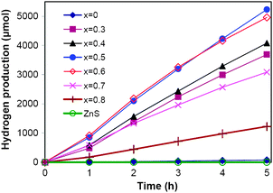 | ||
| Fig. 7 Time course for hydrogen production over ZnxCd1−xS (0 ≤ x ≤ 0.8) samples synthesized by the solvothermal method (180 °C, 24 h) and pure ZnS sample; reaction conditions: 0.1 g catalyst, 100 mL aqueous solution containing 0.7 M Na2S and 0.5 M Na2SO3, 300 W Xe lamp (λ ≥ 420 nm). | ||
This work has demonstrated that in the absence of expensive metal elements, the Zn–Cd sulfide system which only consists of earth abundant components can be developed as efficient photocatalysts. For binary or ternary metal sulfides used in photocatalytic water splitting, the formation of solid solutions is one of the most important factors to improve the photocatalytic activity.26–28 Since the band structure of solid solution semiconductors can be controlled by varying the compositions, effective visible light absorption and suitable band positions can be obtained in solid solution semiconductors. In this study, we adopted the one-step solvothermal method to prepare ZnxCd1−xS solid solutions. When the x value is between 0.3 and 0.5, homogeneous solid solutions between ZnS and CdS can be obtained, which should be an important reason leading to high activities of our samples. In addition, the crystallinity of these solid solution samples is relatively high based on the HRTEM analysis. It should be mentioned that the use of Na2S and Na2SO3 as sacrificial reagents in this work and many others for hydrogen production could be a hurdle for the sustainability considering the practical application. Nevertheless, the work here could provide important insights on designing of active photocatalysts.
Fig. 8 displays the photocatalytic stability of sample Zn0.5Cd0.5S (synthesized with a reaction time of 24 h) for hydrogen production. It was found that there was about 10% drop in the activity after each run of 5 h photoreaction. In the first run, a total of 5112 μmol of hydrogen gas was produced, while the total amount in the third run was 4259 μmol. The pH values measured before the first run and after the third run were 12.1 and 11.5, respectively, which could be due to the slight difference in the concentrations of the sacrificial reagents, Na2S and Na2SO3. Before the fourth run, the photocatalyst was collected by centrifugation and redispersed in the fresh aqueous solution of the sacrificial reagents. However, the hydrogen production rate further dropped by about 10%, indicating that the consumption of the sacrificial reagents was not the main reason for the activity loss. To investigate the factors causing the activity loss, samples before and after the stability study were analyzed. The composition data from ICP analysis showed that the ratio of Zn2+:Cd2+ decreased from 42:58 to 39:61, indicating the leaching of a small percentage of Zn2+ ions during the reaction. This is probably the reason for (i) a lower crystallinity as shown in the XRD pattern (Fig. 9a), and (ii) a tail-up phenomenon in the range of 500–800 nm in the UV-vis DRS curve (Fig. 9c) of the sample after the reaction. The above results suggested that the leaching of Zn2+ ions during the photoreaction could lead to more lattice defects in the solid solution, although there were no obvious morphological changes as displayed in the SEM image (Fig. 9b). Fig. 9d shows the XPS results of the sample before and after the stability study. The binding energies of Zn 2p and Cd 3d were found in good agreement with the previously reported values with small variations.42,43 No obvious shift was found in the binding energies before and after the reaction. Consistent with the ICP results, the surface ratio of Cd:S was kept unchanged while that of Zn:S was reduced from 27:73 to 23:77, suggesting the leaching of surface Zn2+. It is known that the valence band width of a semiconductor controls the mobility of photogenerated holes. The wider the valence band width, the higher the mobility of the holes, and the better the photo-oxidation ability of the holes.44 Since ZnS has a wider valence band width and a more negative valence band maximum position than those of CdS, the photocorrosion of ZnS is expected to be more severe than that of CdS.45,46 Further study is undergoing to improve the stability of the ZnxCd1−xS photocatalysts by suppressing the leaching of Zn2+ ions.
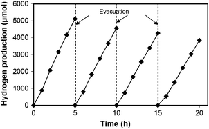 | ||
| Fig. 8 Hydrogen production during the stability study for sample Zn0.5Cd0.5S synthesized by the solvothermal method (180 °C, 24 h) under visible light irradiation. The photocatalytic reaction conditions were the same as those in Fig. 7. | ||
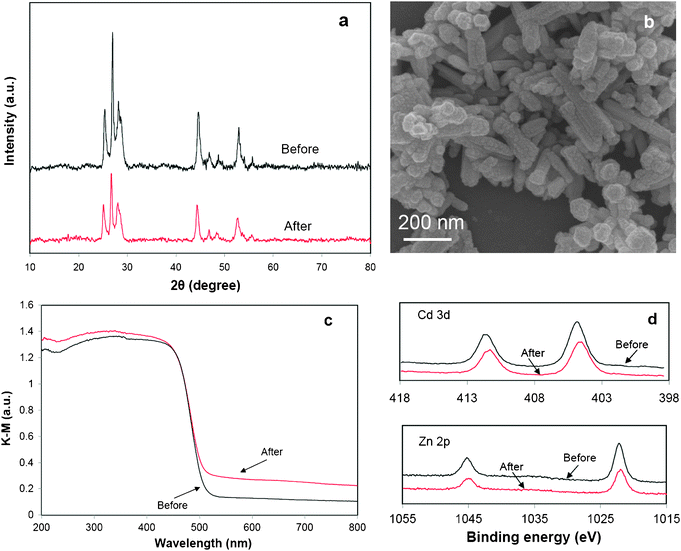 | ||
| Fig. 9 Comparison of properties of sample Zn0.5Cd0.5S before and after 20 h photocatalytic reaction under visible light irradiation, (a) XRD, (b) SEM image (after reaction), (c) UV-vis DRS, (d) XPS of Cd 3d and Zn 2p. | ||
Conclusions
ZnxCd1−xS solid solution photocatalysts were successfully synthesized via a facile solvothermal route using EDA as the solvent and TAA as the sulfur source. Due to different coordinating abilities of EDA to Zn2+ and Cd2+ ions as well as the promotional effects of EDA on the growth of ZnS and CdS along different directions, an obvious morphological evolution process from metal complex microplates to ZnxCd1−xS nanorods and nanoparticles was observed. The ZnxCd1−xS products were found to be homogeneous solid solutions with 0.3 ≤ x ≤ 0.5 in the precursor solutions. In the absence of any expensive metal components and co-catalysts, excellent photocatalytic activities were obtained over Zn0.5Cd0.5S with a hydrogen production rate of 1097 μmol h−1 (λ ≥ 420 nm) and the corresponding quantum efficiency of 30.4% (at 420 nm). A slight activity loss during the long time photoreaction was found to be attributed to the leaching of Zn2+ ions which caused lower crystallinity and more lattice defects in the solid solution photocatalysts.Acknowledgements
The authors greatly acknowledge the research funding support from Ministry of Education, Singapore (AcRF grant no.: ARC25/08) and Y. B. Wang acknowledges the research scholarship from Nanyang Technological University.Notes and references
- A. Midilli, M. Ay, I. Dincer and M. A. Rosen, Renewable Sustainable Energy Rev., 2005, 9, 255 CrossRef CAS.
- A. Fujishima and K. Honda, Nature, 1972, 238, 37 CrossRef CAS.
- F. E. Osterloh, Chem. Mater., 2008, 20, 35 CrossRef CAS.
- K. Maeda and K. Domen, J. Phys. Chem. C, 2007, 111, 7851 CAS.
- A. Kudo and Y. Miseki, Chem. Soc. Rev., 2009, 38, 253 RSC.
- W. J. Luo, Z. S. Li, X. J. Jiang, T. Yu, L. F. Liu, X. Y. Chen, J. H. Ye and Z. G. Zou, Phys. Chem. Chem. Phys., 2008, 10, 6717 RSC.
- K. Takanabe, K. Kamata, X. C. Wang, M. Antonietti, J. Kubota and K. Domen, Phys. Chem. Chem. Phys., 2010, 12, 13020 RSC.
- I. Tsuji, H. Kato and A. Kudo, Angew. Chem., Int. Ed., 2005, 44, 3565 CrossRef CAS.
- Y. X. Li, G. Chen, C. Zhou and J. X. Sun, Chem. Commun., 2009, 2020 RSC.
- H. J. Yan, J. H. Yang, G. J. Ma, G. P. Wu, X. Zong, Z. B. Lei, J. Y. Shi and C. Li, J. Catal., 2009, 266, 165 CrossRef CAS.
- K. Maeda, K. Teramura, D. L. Lu, T. Takata, N. Saito, Y. Inoue and K. Domen, Nature, 2006, 440, 295 CrossRef CAS.
- K. Maeda, M. Higashi, D. L. Lu, R. Abe and K. Domen, J. Am. Chem. Soc., 2010, 132, 5858 CrossRef CAS.
- W. Zhang, Z. Y. Zhong, Y. S. Wang and R. Xu, J. Phys. Chem. C, 2008, 112, 17635 CAS.
- W. Zhang and R. Xu, Int. J. Hydrogen Energy, 2009, 34, 8495 CrossRef CAS.
- Y. Wang, Y. Wang and R. Xu, Int. J. Hydrogen Energy, 2010, 35, 5245 CrossRef CAS.
- W. Zhang, Y. B. Wang, Z. Wang, Z. Y. Zhong and R. Xu, Chem. Commun., 2010, 46, 7631 RSC.
- K. Ikcue, S. Shiiba and M. Machida, Chem. Mater., 2010, 22, 743 CrossRef.
- S. Ikeda, T. Nakamura, T. Harada and M. Matsumura, Phys. Chem. Chem. Phys., 2010, 12, 13943 RSC.
- N. Bao, L. Shen, T. Takata and K. Domen, Chem. Mater., 2008, 20, 110 CrossRef CAS.
- B. Girginer, G. Galli, E. Chiellini and N. Bicak, Int. J. Hydrogen Energy, 2009, 34, 1176 CrossRef CAS.
- D. Jing and L. Guo, J. Phys. Chem. B, 2006, 110, 11139 CrossRef CAS.
- J. S. Jang, U. A. Joshi and J. S. Lee, J. Phys. Chem. C, 2007, 111, 13280 CAS.
- X. W. Wang, G. Liu, Z. G. Chen, F. Li, L. Z. Wang, G. Q. Lu and H. M. Cheng, Chem. Commun., 2009, 3452 RSC.
- A. Kudo and M. Sekizawa, Catal. Lett., 1999, 58, 241 CrossRef CAS.
- A. Kudo and M. Sekizawa, Chem. Commun., 2000, 1371 RSC.
- I. Tsuji, H. Kato, H. Kobayashi and A. Kudo, J. Am. Chem. Soc., 2004, 126, 13406 CrossRef CAS.
- I. Tsuji, H. Kato, H. Kobayashi and A. Kudo, J. Phys. Chem. B, 2005, 109, 7323 CrossRef CAS.
- I. Tsuji, H. Kato and A. Kudo, Chem. Mater., 2006, 18, 1969 CrossRef CAS.
- F. del Valle, A. Ishikawa, K. Domen, J. A. Villoria de la Mano, M. C. Sánchez-Sánchez, I. D. González, S. Herreras, N. Mota, M. E. Rivas, M. C. Álvarez Galván, J. L. G. Fierro and R. M. Navarro, Catal. Today, 2009, 143, 51 CrossRef CAS.
- C. Xing, Y. Zhang, W. Yan and L. Guo, Int. J. Hydrogen Energy, 2006, 31, 2018 CrossRef CAS.
- K. Zhang, D. Jing, C. Xing and L. Guo, Int. J. Hydrogen Energy, 2007, 32, 4685 CrossRef CAS.
- L. Wang, W. Wang, M. Shang, W. Yin, S. Sun and L. Zhang, Int. J. Hydrogen Energy, 2010, 35, 19 CrossRef CAS.
- A. M. Roy and G. C. De, J. Photochem. Photobiol., A, 2003, 157, 87 CrossRef CAS.
- X. Wang, G. Liu, Z. G. Chen, F. Li, G. Q. Lu and H. M. Cheng, Electrochem. Commun., 2009, 11, 1174 CrossRef CAS.
- J. D. Bryan, D. A. Schwartz and D. R. Gamelin, J. Nanosci. Nanotechnol., 2005, 5, 1472 CrossRef CAS.
- G. Q. Ren, Z. Lin, C. Wang, W. Z. Liu, J. Zhang, F. Huang and J. K. Liang, Nanotechnology, 2007, 18, 035705 CrossRef.
- J. S. Jang, C. J. Yu, S. H. Choi, S. M. Ji, E. S. Kim and J. S. Lee, J. Catal., 2008, 254, 144 CrossRef CAS.
- S. Sperinck, T. Becker, K. Wright and W. R. Richmond, J. Inclusion Phenom. Macrocyclic Chem., 2009, 65, 89 CrossRef CAS.
- S. H. Yu, Y. S. Wu, J. Yang, Z. H. Han, Y. Xie, Y. T. Qian and X. M. Liu, Chem. Mater., 1998, 10, 2309 CrossRef CAS.
- L. Dong, Y. Liu, Y. Zhuo and Y. Chu, Eur. J. Inorg. Chem., 2010, 2504 CAS.
- J. R. Goates, M. B. Gordon and N. D. Faux, J. Am. Chem. Soc., 1952, 74, 835 CrossRef CAS.
- G. Deroubaix and P. Marcus, Surf. Interface Anal., 1992, 18, 39 CrossRef CAS.
- M. Marychurch and G. C. Morris, Surf. Sci., 1985, 154, L251 CrossRef CAS.
- G. Liu, P. Niu, C. Sun, S. C. Smith, Z. Chen, G. Q. Lu and H. M. Cheng, J. Am. Chem. Soc., 2010, 132, 11642 CrossRef CAS.
- Y. N. Xu and W. Y. Ching, Phys. Rev. B, 1993, 48, 4335 CrossRef CAS.
- Y. H. Li, A. Walsh, S. Chen, W. J. Yin, J. H. Yang, J. Li, J. L. F. Da Silva, X. G. Gong and S. H. Wei, Appl. Phys. Lett., 2009, 94, 212109 CrossRef.
Footnote |
| † Electronic supplementary information (ESI) available: Abundance and price of metal elements employed in some representative promising photocatalysts, FTIR spectra and XRD patterns of ZnxCd1−xS samples synthesized under different conditions, the first derivative of the UV-vis DRS curves of ZnxCd1−xS samples, XRD and UV-vis DRS comparison for samples Zn0.5Cd0.5S dried directly after synthesis and aged for 24 h in Na2S solution before drying. SEM image and EDS analysis results of sample Zn0.5Cd0.5S synthesized with a reaction time of 2 h. See DOI: 10.1039/c1cy00143d |
| This journal is © The Royal Society of Chemistry 2011 |