A review of the development of nitrogen-modified carbon-based catalysts for oxygen reduction at USC
Gang
Liu
,
Xuguang
Li
,
Jong-Won
Lee
and
Branko N.
Popov
*
Center for Electrochemical Engineering, Department of Chemical Engineering, University of South Carolina, Columbia, SC 29208, USA. E-mail: popov@cec.sc.edu; Fax: +1 (803) 777 8265; Tel: +1 (803) 777 7314
First published on 14th February 2011
Abstract
In this review, the development of non-precious nitrogen-modified carbon-based catalysts for oxygen reduction reaction (ORR) is described, mainly focusing on our research at the University of South Carolina (USC). Metal-free; metal-containing; and template-assisted metal-containing, nitrogen-modified carbon-based catalysts were developed in our group in the past few years. From the characterization and analysis of the synthesized nitrogen-modified carbon-based catalysts, we proposed our viewpoints on the nature of the ORR active sites and performance degradation mechanisms of this type of non-precious metal catalysts. Suggested research and development directions for non-precious nitrogen-modified carbon-based catalysts were also discussed.
1. Introduction
Platinum (Pt) is the most commonly used electrocatalyst for the four-electron oxygen reduction to water in acidic environments with low overpotential and high stability.1,2 However, even on pure Pt, the overpotential caused by sluggish kinetics is in excess of 300 mV (NHE) from the thermodynamic potential for oxygen reduction reaction (ORR).3,4 Due to the high cost and limited availability of Pt, there has been a considerable amount research conducted on non-precious metal catalysts.5Since Jasinski's discovery of the catalytic properties of cobalt (Co) phthalocyanines for oxygen reduction in alkaline environments,6 there has been increased research on non-precious metal catalysts such as: (i) transition metal macrocyclic compounds (e.g., Co phthalocyanines and iron (Fe) tetramethoxyphenyl porphyrin),7–17 (ii) vacuum-deposited Co and Fe compounds (e.g., Co–C–N and Fe–C–N),18,19 and (iii) metal carbides, nitrides and oxides (e.g., MoNx, ZrOxNy/C, ZrO2).20–24 However, none of the catalysts reported in the literature fully meets the requirements of electrocatalysts for oxygen reduction in polymer electrolyte membrane (PEM) fuel cells4 due to: (i) low catalytic activity, (ii) poor stability, (iii) low selectivity toward four-electron reduction of oxygen to water (large amount of hydrogen peroxide, > 5%), and (iv) high electronic resistance.
The nature of the ORR active sites of nitrogen-modified carbon-based catalysts is still being debated. One of the hypotheses, and the relevant reaction mechanisms of oxygen reduction on these catalysts, is that the metal-N4 center bound to the carbon support is catalytically active, and the central metal ion in the macrocycle plays a crucial role in the ORR.7–17 For example, from the analysis of Fe-based catalysts by Time-of-Flight Secondary Ion Mass Spectrometry (ToF-SIMS), Dodelet and his co-workers9,10,15 maintain that two different catalytic sites (FeN4/C and FeN2/C) for oxygen reduction exist simultaneously in the catalysts, irrespective of the Fe precursors used. Here, FeN4/C represents an Fe ion coordinated to four nitrogen atoms of the pyrrole-type, and FeN2/C stands for an Fe ion coordinated to two nitrogen atoms of the pyridinic-type.
Yeager25,26 and Wiesener27 suggested that the transition metal does not act as an active site for oxygen reduction, but rather serves primarily to facilitate the stable incorporation of nitrogen into the graphitic structure of carbon during high-temperature pyrolysis of metal-nitrogen complexes. According to ref. 25, after heat-treatment of Co-TMPP and Fe-TMPP at 800 °C, no Co or Fe was detected in the Mössbauer spectra in a form corresponding to coordination with nitrogen, thus indicating decomposition of the metal-N4 structure during high temperature pyrolysis. According to Maldonado and Stevenson,28,29 the strong basicity of N-doped carbon facilitates reductive O2 adsorption and the decomposition of peroxide species, thereby increasing the catalytic activity. Gong et al.30 synthesized N-doped carbon nanotube arrays with high ORR activity even after removal of the Fe residue by an electrochemical purification process. From the quantum mechanics calculations with density functional theory, it was also found that carbon atoms adjacent to nitrogen dopants possess a substantially high positive charge density to counterbalance the strong electronic affinity of the nitrogen atom. The nitrogen-induced charge delocalization could facilitate the Yeager model (bridge model) chemisorption of O2 on the N-doped carbon nanotube catalysts, which could effectively weaken the O–O bonding to facilitate the ORR.
Nitrogen-modified carbon-based catalysts can be prepared using implantation, through NH3 or HCN treatment of an oxidized carbon. The electrochemical measurements taken at USC indicated that the onset potential of oxygen reduction on the NH3-treated Ketjen black is approximately 0.5 V (NHE) in comparison with 0.3 V (NHE) with the untreated carbon.31 The quantum mechanical calculations on cluster models show that carbon radical sites formed adjacent to substitutional nitrogen in the NH3-treated carbon are active sites for the ORR.31 Matter et al.32,33 prepared an active non-metal catalyst for oxygen reduction by the decomposition of acetonitrile vapour at 900 °C over a pure alumina support and an alumina support containing 2 wt% Fe or 2 wt% Ni. The catalysts showed only 100 mV (NHE) greater overpotential than Pt catalyst for oxygen reduction. The authors also studied the role of nanostructures in nitrogen-modified carbon-based catalyst for oxygen reduction. The most active catalyst was obtained when an Fe-containing alumina support is used. The authors also found that the high activity of the catalysts was attributed to significantly high amounts of pyridinic-N.
At USC, novel routes were developed to synthesize metal-free nitrogen-modified carbon-based catalyst without using metal precursors.34,35 For increasing the catalytic activity and stability of the metal-free nitrogen-modified carbon-based catalysts, transition metals were incorporated for the synthesis of metal-containing nitrogen-modified carbon-based catalysts.36,37 Subsequently, a template-assisted pyrolysis method was developed to synthesize template-assisted metal-containing nitrogen-modified carbon-based catalyst in order to further increase the catalytic activity and stability.38 In the past few years, the ORR active sites and performance degradation mechanisms were proposed based on our research on nitrogen-modified carbon-based catalysts. In this review paper, a brief account of these efforts, with a primary focus on our own work, were revealed.
2. Synthesis and characterization of USC non-precious metal catalysts
2.1 Catalyst synthesis
The nitrogen-modified carbon-based catalysts discussed in this review contain: (i) metal-free nitrogen-modified carbon-based catalysts (USC-1); (ii) metal-containing nitrogen-modified carbon-based catalysts (USC-2) and (iii) template-assisted metal-containing nitrogen-modified carbon-based catalysts (USC-3).Several metal-free nitrogen-modified carbon-based catalysts were synthesized in our group.34,35 In this review, urea-formaldehyde modified carbon (USC-1) was discussed as a typical metal-free nitrogen-modified carbon-based catalyst. USC-1 catalyst was synthesized by a simple addition-condensation reaction of urea and formaldehyde on oxidized carbon, followed by a pyrolysis at 800 °C for 1 h under Ar atmosphere.
The metal-containing nitrogen-modified carbon-based catalysts (USC-2) were synthesized using USC-1 as a support.36 Typically, USC-2 catalyst was synthesized by the pyrolysis of cobalt-iron-ethylenediamine (CoFe-EDA) chelate complex on USC-1 at 800 °C for 1 h in an Ar atmosphere, followed by the H2SO4 leaching procedure, and a second-pyrolysis at 800 °C for 3 h in an Ar atmosphere.
The synthesis of a template-assisted metal-containing nitrogen-modified carbon-based catalyst (USC-3) was similar with the synthesis of the USC-2 catalyst. Silica was used as a substitute of USC-1 and as a sacrificial support.38 Typically, CoFe-EDA chelate complexes were pyrolyzed on silica first, followed by the NaOH and H2SO4 leaching procedures, and a second-pyrolysis in an inert atmosphere.
2.2 Electrochemical and physicochemical characterization of the USC non-precious metal catalysts
Rotating disk electrode (RDE) and rotating ring-disk electrode (RRDE) measurements were applied to evaluate the electrocatalytic activity and the ORR selectivity of the USC non-precious metal catalysts in a 0.5 M H2SO4 solution.The single cell measurement was carried out in a single cell with serpentine flow channels (5 cm2Cell Hardware Assembly, Fuel Cell Technologies Inc.). The fuel cell performance was tested at 75 °C with a saturated humidification level. The fuel cell was fed with pure hydrogen and oxygen, or air. Back pressure was applied at 30 psi. The stability test was carried out at a constant potential of 0.5 V for the H2–O2fuel cell and 0.4 V for the H2-air fuel cell.
Different physicochemical characterization such as inductively coupled plasma mass spectroscopy (ICP-MS), X-ray diffraction (XRD), transmission electron microscopy (TEM), X-ray photoelectron spectroscopy (XPS), and extended X-ray absorption fine structure (EXAFS) were applied for the analyses of the ORR active sites and performance degradation mechanisms.
3. Characterization results and discussion of the USC non-precious metal catalysts
3.1 RDE and RRDE measurements
Fig. 1 shows the polarization curves of the oxygen reduction on USC-1, USC-2 and USC-3 catalysts. For comparison, the polarization curve of oxidized carbon was also shown in Fig. 1. It was observed that the oxidized carbon showed an onset potential of about 0.4 V with no smooth diffusion current in the whole potential range. However, after modification of N-containing groups, USC-1 catalyst showed an onset potential of about 0.78 V with a smooth diffusion current under 0.4 V. As for the USC-2 catalyst, after the incorporation of transition metal into the catalyst synthesis, an improved ORR activity was achieved. The onset potential for the ORR on USC-2 catalyst was as high as 0.87 V with a well-defined diffusion limiting current under 0.7 V. When the carbon black was not used in the catalyst synthesis, USC-3 catalyst showed an even further increase in the ORR activity compared with USC-2 catalyst, especially in the kinetic-diffusion control region (0.65–0.87 V). Without the use of carbon black in the catalyst synthesis will increase the nitrogen content in the synthesized catalyst.38 The increase of nitrogen content may contribute to the increase of the ORR activity. This assumption will be further discussed in the following section of the XPS discussion.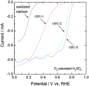 | ||
| Fig. 1 Polarization curves for the oxygen reduction reaction on the USC-1, USC-2 and USC-3 catalysts. The measurements were performed in O2-saturated 0.5 M H2SO4 solution at a potential scan rate of 5 mV s−1 and a rotation speed of 900 rpm. | ||
The amount of H2O2 generated during the oxygen reduction on the oxidized carbon and the synthesized USC non-precious metal catalysts was evaluated by RRDE measurements. The percentage of H2O2 produced during the whole potential range decreased after the nitrogen modification. Table 1 summarizes the amount of H2O2 produced at 0.4 V for the oxidized carbon and the synthesized USC non-precious metal catalysts. The oxidized carbon generated about 20% H2O2 during the ORR at 0.4 V. However, the amounts of H2O2 generated on USC-1, USC-2, and USC-3 catalysts were in the range of 1–4% at 0.4 V. This indicates that the modification of N-containing groups on carbon not only increases the ORR activity, but also improves the selectivity towards oxygen reduction.
| Catalysts | % H2O2 |
|---|---|
| Oxidized carbon | 20 |
| USC-1 | 4.0 |
| USC-2 | 0.7 |
| USC-3 | 0.7 |
It was found that there is an optimum transition metal content in USC-2 and USC-3 catalysts, similar to the previous reports of others.30–40Fig. 2 shows the plot of the oxygen-reduction currents on USC-2 catalysts at 0.6 V as a function of transition metal content (the plot is reproduced from the RDE results on USC-2 catalysts synthesized by the addition of different amounts of transition metals). As shown in Fig. 2, when the transition metal content was lower than about 3 wt%, the ORR activity increased with the increase of transition metal content. Over 3 wt%, the ORR activity decreased slightly and then remained virtually the same.
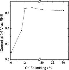 | ||
| Fig. 2 Plot of the oxygen-reduction currents on the USC-2 catalysts at 0.6 V as a function of transition metal content. | ||
3.2 Single cell measurements
Fig. 3a shows the polarization curves of the PEM fuel cells applying USC-1, USC-2, USC-3, and Pt/C as the cathode catalysts. Ohmic potential drop was not compensated for in the measurements. As shown in Fig. 3a, the USC-1 MEA showed an open circuit potential (OCP) of approximately 0.78 V. However, the USC-2 and USC-3 MEAs showed OCPs of approximately 0.87 V. The single cell performance increased in the order of USC-1 MEA < USC-2 MEA < USC-3 MEA, which was consistent with the RDE results. At a current density of 500 mA cm−2, the cell voltage of USC-3 MEA is 0.5 V, which is about 70 mV and 193 mV higher than that of USC-2 MEA and USC-1 MEA, respectively at the same current density. The cell performance of the 2 mg cm−2 loading USC-3 MEA is close to that of Pt/C MEA, with a Pt loading of 0.1 mg cm−2.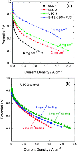 | ||
| Fig. 3 Polarization curves (a) of the PEM fuel cells applying USC-1, USC-2 and USC-3 catalysts as the cathode catalysts and polarization curves (b) of PEM fuel cells applying different loadings of USC-2 catalysts. The experiments were performed using 30 psi back pressure on both anode (H2) and cathode (O2) compartments. Reproduced from ref. 35, 36 and 38 with permission from Elsevier. | ||
Fig. 3b shows the polarization curves of PEM fuel cells applying various loadings of USC-2 catalyst. It is obvious that the cell performance increases with the increase of the catalyst loading, especially at higher current density ranges. At a current density of 1000 mA cm−2, the cell voltage increases from 0.34 V to 0.38 and 0.42 V as the loading increases from 2 mg cm−2 to 4 and 6 mg cm−2.
3.3 Inductively coupled plasma mass spectroscopy (ICP-MS) measurements
Table 2 summarizes the transition metal content of USC-1 and USC-2 catalysts. The transition mental content of USC-1 catalyst was measured at two universities. It was observed that the transition metal (Fe and Co) content of USC-1 catalyst was nearly zero, confirming that there was no transition metal in the USC-1 catalyst. Therefore, this gave evidence that, in the absence of any transition metal, nitrogen can be doped into the carbon black and produce active sites for the ORR.41 For the USC-2 catalyst, the Fe and Co content was 1.4 wt% and 4.6 wt%, respectively. From the above RDE measurement discussion we know that the incorporation of transition metals in the catalyst synthesis increases the ORR activity of the USC-2 catalyst. In fact, the incorporation of transition metals in the catalyst synthesis facilitates the incorporation of nitrogen into the carbon structure. This will be confirmed in the following XPS discussion.3.4 XRD measurements
Fig. 4 shows the XRD patterns of the oxidized carbon, USC-1, USC-2, and USC-3 catalysts. As shown in Fig. 4, only C(002) and C(101) diffraction peaks were shown in the XRD pattern of USC-1 catalyst. As for USC-2 and USC-3 catalysts, some small peaks occurred around 45°, which could be assigned to a mixture of the metallic phases (such as Fe, Co, and Fe–Co alloy) and the Fe3C phase.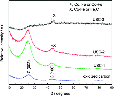 | ||
| Fig. 4 XRD patterns of the oxidized carbon, USC-1, USC-2 and USC-3 catalysts. Reproduced from ref. 36 with permission from Elsevier. | ||
3.5 TEM measurements
Fig. 5 shows the TEM images of the USC-1, USC-2, and USC-3 catalysts. As for the TEM image of the USC-1 catalyst, there is no difference with the typical graphitic carbon structures. No metal particle can be seen in the TEM image of USC-1 catalyst, which confirms the absence of any metal in the catalyst. As for USC-2 and USC-3 catalysts, obvious metal particles were seen in the TEM images, which were coated with layers of graphitic carbon. The metal particle density on USC-3 catalyst was higher than that on USC-2 catalyst due to the absence of carbon black in the synthesis of USC-3 catalyst. There were no bare metal particles on the top surface of the USC-2 and USC-3 catalysts. Since oxygen reduction reaction is a surface reaction, this confirms that transition metal does not take part in the ORR.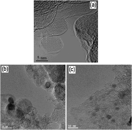 | ||
| Fig. 5 TEM images of the USC-1, USC-2 and USC-3 catalysts. Reproduced from ref. 36 and 38 with permission from Elsevier. | ||
3.6 XPS measurements
The nitrogen functional groups in coals and chars are well studied by Pels et al.42, which are in the form of pyridinic-N (398.6 ± 0.3 eV), pyrrolic-N/pyridone-N (400.5 ± 0.3 eV), quaternary-N/pyridinic-N–H (401.3 ± 0.3 e), and pyridine-N-oxide (402–405 eV).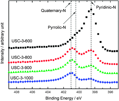 | ||
| Fig. 6 XPS spectra of N 1s region obtained for the USC-3 catalysts heat-treated at 600–1000 °C. | ||
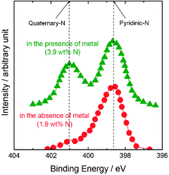 | ||
| Fig. 7 XPS spectra of N 1s region obtained for the USC-2 catalysts synthesized in the presence and absence of transition metal. Reproduced from ref. 36 with permission from Elsevier. | ||
3.7 EXAFS measurements
Fig. 8 shows the K1-weighted EXAFS spectra in R space for the USC-2 catalysts pyrolyzed at different temperatures. In this study, only the transition metal Co was added in the preparation of the measured USC-2 catalysts. For comparison, a reference spectrum of a pure cobalt foil was also shown in Fig. 8. This indicates that there is only Co–N interaction in the USC-2 catalyst before pyrolysis, and confirms the presence of the Co–N chelate complex on the carbon surface. As the pyrolysis temperature was increased to 600 °C, the Co–N decreased and the Co–Co peak became strong. When the pyrolysis temperature increased to 800 °C and above temperatures, the Co–N peak completely disappeared and only the Co–Co peak was observed. This indicated that there was no Co–N structure in the USC-2 catalyst when the catalyst was pyrolyzed at temperatures higher than 800 °C. The EXAFS results confirmed that Metal-N4 or Metal-N2 structures are not stable after high temperature pyrolysis and will not be the ORR active sites based on our research results.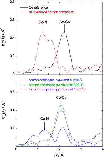 | ||
| Fig. 8 K1-weighted EXAFS spectra in R space for the USC-2 catalysts pyrolyzed at different temperatures. Reproduced from ref. 36 with permission from Elsevier. | ||
3.8 The nature of the ORR active sites
There are two major viewpoints on the nature of the ORR active sites of these nitrogen-modified carbon-based catalysts.7–17,25–38 Firstly, Fe(Co)-N4 and Fe(Co)-N2 centers bound to the carbon support are believed to be catalytically active and the central transition metal plays a crucial role in the ORR. Secondly, nitrogen functional groups doped in the carbon matrix are believed to be active for the ORR. The transition metals do not take part in the ORR, but the addition of transition metal in the catalyst synthesis facilitates the incorporation of nitrogen into the carbon matrix, which can increase the ORR active site density on the catalysts.Based on the research of our group, we support the second opinion on the ORR active sites. In the past few years, the group first prepared different metal-free nitrogen-modified carbon-based catalysts. Most of these metal-free nitrogen-modified carbon-based catalysts showed an onset potential of about 0.8 V and promising ORR activity, both in the electrolyte solutions and in the single cells. Most importantly, it had been confirmed that there was no transition metal in the final metal-free nitrogen-modified carbon-based catalysts according to the ICP-MS results. The only difference between the metal-free nitrogen-modified carbon-based catalysts and carbon black is that there is nitrogen in the metal-free nitrogen-modified carbon-based catalysts. Thus, it is reasonable to say that it is the nitrogen doped in the carbon matrix that catalyzes the ORR in the metal-free nitrogen-modified carbon-based catalysts.
Next, our group prepared metal-containing nitrogen-modified carbon-based catalysts. From the TEM analyses we know that the visible transition metal particles are coated with carbon layers in the final catalysts. Moreover, the EXAFS results confirm that transition metal-N bond decomposes at temperatures over 800 °C. Our catalysts were all pyrolyzed at temperatures ≥ 800 °C, which certified the absence of transition metal-N structures in our catalysts. Since the ORR is an interface reaction, the TEM and EXAFS results together reveal that the remaining transition metals in the metal-containing nitrogen-modified carbon-based catalysts are not part of the active site for the ORR. However, the incorporation of transition metals in the catalyst synthesis does increase the final ORR activity of the synthesized catalysts, which probably corresponds to the positive nitrogen doping into the carbon matrix and the enhancement of graphitic carbon structures in the presence of transition metal.
According to our XPS analyses,38,41,43 there are only pyridinic-N, quaternary-N and pyridine-N-oxide in the nitrogen-modified carbon-based catalysts when the catalysts are pyrolyzed at temperatures of 800 °C and above. The pyridinic-N can be found on the edge of a carbon plane. It should be mentioned that pyridinic-N is a type of nitrogen that contributes one p-electron to the aromatic π-system and has a lone electron pair in the plane of the carbon matrix. This increases the electron-donating ability of the nitrogen-modified carbon-based catalysts and promotes the process of the ORR.41 The quaternary-N is a type of nitrogen that bonds to three carbon atoms in the plane of the carbon matrix. Ikeda44et al. found that the O2 molecule is preferentially adsorbed at carbon sites on graphene-like zigzag edges if a quaternary-N is located nearby as determined by Parrinello MD modelling. The following experimental research on nitrogen-modified carbon-based catalysts by Niwa et al.45 also shows that the catalysts with a higher content of quaternary-N have higher ORR activity. Based on the above discussion and the previous work of others, it is reasonable to assume that only doped nitrogen atoms in the carbon matrix (more exactly, pyridinic-N and quaternary-N) are the ORR active sites.
3.9 Degradation mechanisms of nitrogen-modified carbon-based catalysts in PEM fuel cells
Fig. 9 shows a typical plot of the current density at 0.5 V as a function of time for an H2–O2fuel cell using a nitrogen-modified carbon-based catalyst as cathode catalyst. It is evident that there is a quick degradation in the first a few hours' operation, followed by relatively low degradation in the remainder of the operation. This phenomenon is normal and has been revealed in various literature.46–49 According to the studies in our group, the decay of the fuel cell performance is mainly due to the deterioration of the ORR active sites and the water flooding of the electrodes.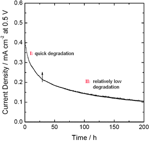 | ||
| Fig. 9 A typical plot of the current density at 0.5 V as a function of time for an H2–O2fuel cell using nitrogen-modified carbon-based catalyst as cathode catalyst. | ||
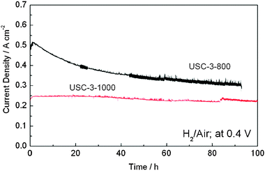 | ||
| Fig. 10 Stability tests of H2-air fuel cells using USC-3 catalysts (pyrolyzed at 800 °C and 1000 °C) as cathode catalysts at 0.4 V. Reproduced from ref. 38 with permission from Elsevier. | ||
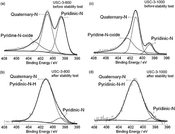
To identify the reasons why the performance degradation between USC-3-800 and USC-3-1000 catalysts is different, the change of the ORR active sites of the two catalysts before and after the stability test was first evaluated by XPS measurements. Fig. 11 shows the XPS spectra of N 1s region for the USC-3 catalysts pyrolyzed at 800 °C and 1000 °C, both before and after the stability test. The contributions of the various nitrogen species to the N 1s peaks are summarized in Table 3. The N 1s spectra for USC-3-800 and USC-3-1000 catalysts before the stability test can be deconvoluted into three peaks; (pyridinic-N, quaternary-N, and pyridine-N-oxide). As shown in Table 3, the total nitrogen content of USC-3-800 and USC-3-1000 catalysts before the stability test are 5.93 at% and 1.90 at%, respectively. More specifically, the pyridinic-N contents of USC-3-800 and USC-3-1000 catalysts before the stability test are 37.1% and 10.5%, respectively. During the high temperature pyrolysis, nitrogen functional species will be burned out of the carbon matrix, and part of the pyridinic-N is further converted to quaternary-N.38,41,42 After the stability test, the deconvoluted N 1s peaks for the USC-3 catalysts were similar, with a broad peak, which can be deconvoluted into two peaks at about 401.4 eV and 398.6 eV. It is obvious that the pyridine-N-oxide peak disappeared after the stability test and the intensity of the pyridinic-N peak decreased dramatically.
 | ||
| Fig. 11 XPS spectra of N 1s region for the USC-3 catalysts pyrolyzed at 800 °C and 1000 °C, both before and after the stability test. Reproduced from ref. 38 with permission from Elsevier. | ||
| Sample | Total N (at%) | XPS analysis (%) | Binding energy/eV | |||||
|---|---|---|---|---|---|---|---|---|
| N | N1 | N2 | N3 | N4 | N1 | N2 | N3 | |
| a N1, pyridinic-N; N2, quaternary-N; N3, pyridinic-N–H; N4, pyridine-N-oxide. N2 and N3 have the same binding energy. b USC-3 catalysts after 100 h stability test. There are N1, N2 and N3 in the USC-3 catalysts after 100 h stability test. | ||||||||
| USC-3-800 | 5.93 | 37.1 | 42.3 | 0 | 20.6 | 398.6 | 400.9 | 403.0 |
| USC-3-1000 | 1.90 | 10.5 | 44.2 | 0 | 45.3 | 398.8 | 401.0 | 402.4 |
| USC-3-800b | — | 8.0 | 92.0 | 0 | 398.7 | 401.1 | — | |
| USC-3-1000b | — | 4.5 | 95.5 | 0 | 398.6 | 401.4 | — | |
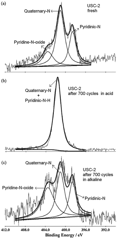
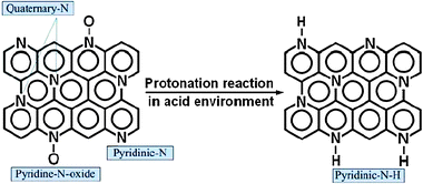
As discussed above, pyridinic-N is a type of nitrogen that bonds to two carbon atoms in the carbon plane with a basic lone pair of electrons. Since this lone pair of electrons is not delocalized into the aromatic π-system, pyridinic-N can be protonated to pyridinic-N–H in an acidic environment.50 In addition, pyridine-N-oxide can also be initially converted to pyridinic-N and then to pyridinic-N–H in an acidic environment. PEM fuel cell using perfluorosulfonic acid polymer membrane as an electrolyte membrane and perfluorosulfonic acid polymer as proton transfer medium in the electrodes, its operating environment is an acidic environment. The XPS data (Fig. 11) confirm that pyridinic-N and pryidine-N-oxide can be converted to pyridinic-N–H in PEM fuel cell operating conditions. We believe the change of pyridinic-N to pyridinic-N–H contributes to the loss of the ORR activity during the fuel cell operation. However, within the accuracy of the XPS measurements, pyridinic-N–H cannot be distinguished from quaternary-N.42 So, after the stability test, the peak at about 401.4 eV may be associated with both quaternary-N and pyridinic-N–H. The small peak at about 398.6 eV could come from the remaining pyridinic-N and/or pyridinic-N derived from pyridine-N-oxide.
To certify the protonation reaction of pyridinic-N and pyridine-N-oxide in the acidic environment and the change of pyridinic-N to pyridinic-N–H contributing to the ORR activity loss, we measured the stability of USC-2 catalyst both in acid and alkaline electrolytes.43 The USC-2 catalyst showed much better stability in alkaline electrolyte than that in acid electrolyte (Fig. 12). The XPS spectra (Fig. 13) further confirmed the protonation reaction of pyridinic-N and pyridine-N-oxide in acid electrolyte and no such protonation reaction happened in alkaline electrolyte. Combining the stability results and the XPS data, it further indicated that the convertion of pyridinic-N to pyridinic-N–H decreases the ORR activity.
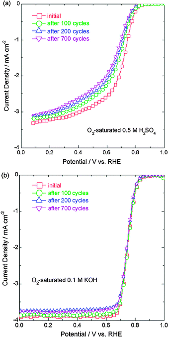 | ||
| Fig. 12 Polarization curves for the oxygen reduction reaction on USC-2 catalyst before and after the potential cycling stability tests, (a) in O2-saturated 0.5 M H2SO4 and (b) in O2-saturated 0.1 M KOH at a potential scan rate of 5 mV s−1 and a rotation speed of 900 rpm. The potential cycling tests were performed in the N2-saturated electrolytes with a scan rate of 10 mV s−1 between 0.8 and 1.2 V vs. RHE for 100, 200 and 700 cycles. Reproduced from ref. 43 with permission from Elsevier. | ||
 | ||
| Fig. 13 XPS spectra of N 1s of (a) the fresh USC-2 catalyst and the catalysts after the potential cycling stability test in (b) 0.5 M H2SO4 and (c) 0.1 M KOH for 700 cycles. Reproduced from ref. 43 with permission from Elsevier. | ||
In contrast, quaternary-N is a type of nitrogen that bonds to three carbon atoms in the carbon plane. There is no lone pair of electrons around quaternary-N in the carbon plane, so it is less susceptible to the protonation reaction. Fig. 14 shows the protonation reaction of various nitrogen functional groups on the surface of a nitrogen-modified carbon-based catalyst in acidic environment. Hence, the change of pyridinic-N to pyridinic-N–H possibly contributes to most of the performance loss during the fuel cell operation.
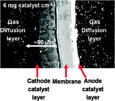 | ||
| Fig. 15 A typical SEM image of MEA cross-section with a cathode catalyst loading of 6 mg cm−2. Reproduced from ref. 35 with permission from Elsevier. | ||
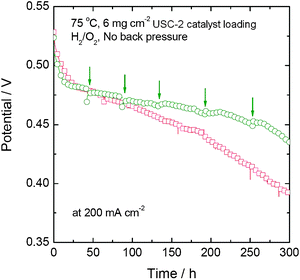 | ||
| Fig. 16 Comparison of the stability tests of two single cells with and without the periodic stop/restart process. | ||
4. Conclusions and outlook
At USC, a metal-free nitrogen-modified carbon-based catalyst was synthesized by a simple addition-condensation reaction on the oxidized carbon. This catalyst showed an onset potential of about 0.75 V (NHE). The incorporation of transition metals into the synthesis of metal-containing nitrogen-modified carbon-based catalysts increased the ORR activity compared with metal-free nitrogen-modified carbon-based catalysts. Non-use of carbon black even further increased the ORR activity. From different physical and electrochemical characterizations on the USC non-precious metal catalysts, it is found that transition metals are not the active sites for the ORR. But the transition metal can facilitate the stable doping of nitrogen functional groups into the carbon matrix, hence an increase in the ORR activity. The active sites for the ORR are believed to be pyridinic-N and quaternary-N. However, pyridinic-N can be protonated in the acidic environment of PEM fuel cells, causing a decrease in the catalyst performance and stability.This work guides future research towards highly active and stable nitrogen-modified carbon-based catalysts, which should exclusively contain high content of quaternary-N groups as well as being pyrolyzed at high temperature. Due to the absence of a protonation reaction of pyridinic-N in alkaline environment, current nitrogen-modified carbon-based catalysts are potential substitutes of Pt catalysts for the cathode of alkaline fuel cells. In addition, in these nitrogen-modified carbon-based catalysts, the nitrogen content is usually in the range of 1–5 at%. That means the active sites density is very low in these catalysts. It will be promising to develop hybrid nitrogen-modified carbon-based catalyst with some other non-precious metal active sites, such as, Zr(Ta)OxNx, MoNx, etc. on its surface.
Acknowledgements
The financial support of the Department of Energy (contract no. DE-FC36-03GO13108) is gratefully acknowledged. Part of this research work was done by Nalini P. Subramanian, Vijayadurda Nallathambi, Swaminatha P. Kumaraguru, Sehkyu Park, and Gang Wu. Their assistance is greatly appreciated.References
- Electrocatalysis, ed. R. R. Adzic, J. Lipkowski and P. N. Ross, VCH Publishers, New York, 1998, p. 197–242 Search PubMed.
- N. M. Markovic and P. N. Ross, Electrocatalysts by design: from the tailored surface to a commercial catalyst, Electrochim. Acta, 2000, 45, 4101–15 CrossRef.
- N. M. Markovic and P. N. Ross, Surface science studies of model fuel cell electrocatalysts, Surf. Sci. Rep., 2002, 45, 117–229 CrossRef CAS.
- H. A. Gasteiger, B. Somapalli and F. T. Wagner, Activity benchmarks and requirements for Pt, Pt-alloy, and non-Pt oxygen reduction catalysts for PEMFCs, Appl. Catal. B: Environ., 2005, 56, 9–35 CrossRef CAS.
- J. Marcinkoski, J. P. Kopasz and T. G. Benjamin, Progress in the US DOE fuel cell subprogram efforts in polymer electrolyte fuel cells, Int. J Hydrogen Energy, 2008, 33, 3894–902 CrossRef CAS.
- R. Jasinski, Anew fuel cell cathode catalyst, Nature, 1964, 201, 1212–3 CAS.
- P. Gouérec and M. Savy, Oxygen reduction electrocatalysis: ageing of pyrolyzed cobalt macrocycles dispersed on an active carbon, Electrochim. Acta, 1999, 44, 2653–61 CrossRef CAS.
- S. L. Gojković, S. Gupta and R. F. Savinell, Heat-treated iron(III) tetramethoxyphenyl porphyrin chloride supported on high-area carbon as an electrocatalyst for oxygen reduction:: Part III Detection of hydrogen-peroxide during oxygen reduction, Electrochim. Acta, 1999, 45, 889–97 CrossRef CAS.
- M. Lefèvre, J. P. Dodelet and P. Bertrand, O2 reduction in PEM fuel cells: Activity and active site structural information for catalysts obtained by the pyrolysis at high temperature of Fe precursors, J Phys. Chem. B, 2000, 104, 11238–47 CrossRef CAS.
- M. Lefèvre, J. P. Dodelet and P. Bertrand, Molecular oxygen reduction in PEM fuel cells: Evidence for the simultaneous presence of two active sites in Fe-based catalysts, J Phys. Chem. B, 2002, 106, 8705–13 CrossRef CAS.
- F. Jaouen, F. Charreteur and J. P. Dodelet, Fe-based catalysts for oxygen reduction in PEMFCs, J Electrochem. Soc., 2006, 153, A689–98 CrossRef CAS.
- K. Sawai and N. Suzuki, Heat-treated transition metal hexacyanometallates as electrocatalysts for oxygen reduction insensitive to methanol, J Electrochem. Soc., 2004, 151(5), A682–88 CrossRef CAS.
- S. Yamazaki, Y. Yamada, T. Ioroi, N. Fujiwara, Z. Siroma, K. Yasuda and Y. Miyazaki, Estimation of specific interaction between several Co porphyrins and carbon black: its influence on the electrocatalytic O2 reduction by the porphyrins, J Electroanal. Chem., 2005, 576, 253–9 CrossRef CAS.
- R. Bashyam and P. Zelenay, A class of non-precious metal composite catalysts for fuel cells, Nature, 2006, 443, 63–6 CrossRef CAS.
- U. I. Koslowski, I. Abs-Wurmbach, S. Fiechter and P. Bogdanoff, Nature of the catalytic centers of porphyrin-based electrocatalysts for the ORR: A correlation of kinetic current density with the site density of Fe-N4 centers, J Phys. Chem. C, 2008, 112, 15356–66 CrossRef CAS.
- R. Baker, D. P. Wilkinson and J. Zhang, Electrocatalytic activity and stability of substituted iron phthalocyanines towards oxygen reduction evaluated at different temperatures, Electrochim. Acta, 2008, 53, 6906–19 CrossRef CAS.
- S. A. Mamuru, K. I. Ozoemena, T. Fukuda, N. Kobayashi and T. Nyokong, Studies on the heterogeneous electron transport and oxygen reduction reaction at metal (Co, Fe) octabutylsulfonylphthalocyanines supported on multi-walled carbon nanotube modified graphite electrode, Electrochim. Acta, 2010, 55, 6367–75 CrossRef CAS.
- R. Yang, J. R. Dahn, A. Bonakdarpour and E. B. Easton, Co-C-N oxygen reduction catalysts prepared by combinatorial magnetron sputter deposition, ECS Trans., 2006, 3, 221–30 Search PubMed.
- E. B. Easton, A. Bonakdarpour, R. Yang, D. A. Stevens, D. G. O'Neill and G. Vernstrom, et al., Thermally treated Fe-C-N oxygen reduction catalysts prepared by vacuum deposition, ECS Trans., 2006, 3, 241–8 Search PubMed.
- H. Zhong, H. Zhang, G. Liu, Y. Liang, J. Hu and B. Yi, A novel non-noble electrocatalyst for PEM fuel cell based on molybdenum nitride, Electrochem. Commun., 2006, 8, 707–12 CrossRef CAS.
- G. Liu, H. Zhang, M. Wang, H. Zhong and J. Chen, Preparation, characterization of ZrOxNy/C and its application in PEMFC as an electrocatalyst for oxygen reduction, J Power Sources, 2007, 172, 503–10 CrossRef.
- K. D. Nam, A. Ishihara, K. Matsuzawa, S. Mitsushima and K. Ota, Partially oxidized niobium carbonitride as non-platinum cathode for PEFC, Electrochem. Solid-State Lett., 2009, 12, B158–60 CrossRef CAS.
- Y. Ohgi, A. Ishihara, K. Matsuzawa, S. Mitsushima and K. Ota, Zirconium oxide-based cathode without platinum group metals for PEFC, ECS Trans., 2009, 25, 129–39 Search PubMed.
- Y. Ohgi, A. Ishihara, K. Matsuzawa, S. Mitsushima and K. Ota, Zirconium oxide-based compound as new cathode without platinum group metals for PEFC, J Electrochem. Soc., 2010, 157, B885–91 CrossRef CAS.
- E. Yeager, Electrocatalysts for O2 reduction, Electrochim. Acta, 1984, 29, 1527–37 CrossRef CAS.
- E. Yeager, Dioxygen electrocatalysis: mechanisms in relation to catalyst structure, J Mol. Catal., 1986, 38, 5–25 CrossRef CAS.
- K. Wiesener, N4-chelates as electrocatalyst for cathodic oxygen reduction, Electrochim. Acta, 1986, 31, 1073–8 CrossRef CAS.
- S. Maldonado, S. Morin and K. J. Stevenson, Direct preparation of carbon nanofiber electrodes via pyrolysis of iron(II) phthalocyanine: Electrocatlytic aspects for oxygen reduction, J Phys. Chem. B, 2004, 108, 11375–83 CrossRef CAS.
- S. Maldonado, S. Morin and K. J. Stevenson, Influence of nitrogen doping on oxygen reduction electrocatalysis at carbon nanofiber electrodes, J Phys. Chem. B, 2005, 109, 4707–16 CrossRef CAS.
- K. Gong, F. Du, Z. Xia, M. Durstock and L. Dai, Nitrogen-doped carbon nanotube arrays with high electrocatalytic activity for oxygen reduction, Science, 2009, 323, 760–4 CrossRef CAS.
- R. A. Sidik, A. B. Anderson, N. P. Subramanian, S. P. Kumaraguru and B. N. Popov, O2 reduction on graphite and nitrogen-doped graphite: Experiment and theory, J. Phys. Chem. B, 2006, 110, 1787–93 CrossRef CAS.
- P. H. Matter, L. Zhang and U. S. Ozkan, The role of nanostructure in nitrogen-containing carbon catalysts for the oxygen reduction reaction, J Catal., 2006, 239, 83–96 CrossRef CAS.
- P. H. Matter, E. Wang and U. S. Ozkan, Preparation of nanostructured nitrogen-containing carbon catalysts for the oxygen reduction reaction from SiO2- and MgO-supported metal particles, J. Catal., 2006, 243, 395–403 CrossRef CAS.
- V. Nallathambi, X. Li, J. W. Lee and B. N. Popov, Development of nitrogen-modified carbon-based catalysts for oxygen reduction in PEM fuel cells, ECS. Trans., 2008, 16, 405–17 Search PubMed.
- N. P. Subramanian, X. Li, V. Nallathambi, S. P. Kumaraguru, H. Colon-Mercado, G. Wu, J. W. Lee and B. N. Popov, Nitrogen-modified carbon-based catalysts for oxygen reduction reaction in polymer electrolyte membrane fuel cells, J Power Sources, 2009, 188, 38–44 CrossRef CAS.
- V. Nallathambi, J. W. Lee, S. P. Kumaraguru, G. Wu and B. N. Popov, Development of high performance carbon composite catalysts for oxygen reduction reaction in proton exchange membrane fuel cells, J Power Sources, 2008, 183, 34–42 CrossRef CAS.
- G. Liu, X. Li and B. N. Popov, Stability study of nitrogen-modified carbon composite catalysts for oxygen reduction reaction in polymer electrolyte membrane fuel cells, ECS Trans., 2009, 25, 1251–9 Search PubMed.
- G. Liu, X. Li, P. Ganesan and B. N. Popov, Studies of oxygen reduction reaction active sites and stability of nitrogen-modified carbon composite catalysts for PEM fuel cells, Electrochim. Acta, 2010, 55, 2853–8 CrossRef CAS.
- F. Jaouen and J. P. Dodelet, Average turn-over frequency of O2 electro-reduction for Fe/N/C and Co/N/C catalysts in PEFCs, Electrochim. Acta, 2007, 52, 5975–84 CrossRef CAS.
- G. Wu, Z. Chen, K. Artyushkova, F. H. Garzon and P. Zelenay, Polyaniline-derived non-precious catalyst for the polymer electrolyte fuel cell cathode, ECS Trans., 2008, 16, 159–70 Search PubMed.
- G. Liu, X. Li, P. Ganesan and B. N. Popov, Development of non-precious metal oxygen-reduction catalysts for PEM fuel cells based on N-doped ordered porous carbon, Appl. Catal. B: Environ., 2009, 93, 156–65 CrossRef CAS.
- J. R. Pels, F. Kapteijn, J. A. Moulijn, Q. Zhu and K. M. Thomas, Evolution of nitrogen functionalities in carbonaceous materials during pyrolysis, Carbon, 1995, 33, 1641–53 CrossRef CAS.
- X. Li, G. Liu and B. N. Popov, Activity and stability of non-precious metal catalysts for oxygen reduction in acid and alkaline electrolytes, J Power Sources, 2010, 195, 6373–8 CrossRef CAS.
- T. Ikeda, M. Boero, S. F. Huang, K. Terakura, M. Oshima and J. I. Ozaki, Carbon alloy catalysts: Active sites for oxygen reduction reaction, J Phys. Chem. C, 2008, 112, 14706–9 CrossRef CAS.
- H. Niwa, K. Horiba, Y. Harada, M. Oshima, T. Ikeda, K. Terakura, J. Ozaki and S. Miyata, X-ray absorption analysis of nitrogen contribution to oxygen reduction reaction in carbon alloy cathode catalysts for polymer electrolyte fuel cells, J. Power Sources, 2009, 187, 93–7 CrossRef CAS.
- G. Lalande, R. Côté, G. Tamizhmani, D. Guay, J. P. Dodelet, L. Dignard-Bailey, L. T. Weng and P. Bertrand, Physical, chemical and electrochemical characterization of heat-treated tetracarboxylic cobalt phthalocyanine adsorbed on carbon black as electrocatalysts for oxygen reduction in polymer electrolyte fuel cells, Electrochim. Acta, 1995, 40, 2635–46 CrossRef CAS.
- J. Maruyama and I. Abe, Formation of platinum-free fuel cell cathode catalyst with highly developed nanospace by carbonizing catalase, Chem. Mater., 2005, 17, 4660–7 CrossRef CAS.
- E. Proietti, S. Ruggeri and D. P. Dodelet, Fe-based electrocatalysts for oxygen reduction in PEMFCs using ballmilled graphite powder as a carbon support, J Electrochem. Soc., 2008, 155, B340–8 CrossRef CAS.
- A. Garsuch, K. MacIntyre, X. Michaud, D. A. Stevens and J. R. Dahn, Fuel cell studies on a non-noble metal catalyst prepared by a template-assisted synthesis route, J Electrochem. Soc., 2008, 155, B953–7 CrossRef CAS.
- W. Geng, Y. Kumabe, H. Nakanashi and A. Ohki, Analysis of hydrothermally-treated and weathered coals by X-ray photoelectron spectroscopy (XPS), Fuel, 2009, 88, 644–9 CrossRef CAS.
- X. Li, C. Liu, W. Xing and T. Lu, Development of durable carbon black/titanium dioxide supported macrocycle catalysts for oxygen reduction reaction, J Power Sources, 2009, 193, 470–6 CrossRef CAS.
| This journal is © The Royal Society of Chemistry 2011 |