Two-dimensional zeolites: dream or reality?
Wieslaw J.
Roth†
and
Jiří
Čejka
*
J. Heyrovský Institute of Physical Chemistry, Academy of Sciences of the Czech Republic, v.v.i., Dolejškova 3, CZ-182 23 Prague 8, Czech Republic. E-mail: jiri.cejka@jh-inst.cas.cz; Fax: +420-28658-2307
First published on 8th February 2011
Abstract
Delaminated and pillared zeolites, called here “two-dimensional zeolites”, are a promising and exciting area of solid materials research with high practical potential in adsorption and catalysis. Synthetic approaches for their preparation, crucial issues concerning reliable identification and characterization of these materials, and examples of their catalytic behaviour are highlighted in this contribution. Last, but not least, ideas and challenges for future progress of these materials are addressed.
1. Introduction
Zeolite synthesis, aiming at the discovery of new microporous structures, has been vigorously explored and developed for more than half a century to expand the demonstrated and potential practical benefits of zeolites in heterogeneous catalysis, adsorption and ion-exchange.1–4 This effort has relied essentially on trial and error approach: hydrothermal syntheses carried out at various conditions and starting mixture compositions, although recently new methodologies like high-throughput synthesis have been successfully applied.5 The leading strategy has employed the addition of polar organic molecules, so-called structure directing or templating agents. While such synthesis routes are less attractive commercially, compared with non-organic ones due to higher cost and environmental problems, most zeolites known to date have not been synthesized yet without templating with an appropriate organic molecule.At present, close to 200 different structural types of zeolites have been formally recognized by the Structure Commission of the International Zeolite Association6 and this number is continuously increasing every year. Zeolites are crystalline microporous aluminosilicates having three-dimensional frameworks formed by SiO4 and AlO4 corner-sharing tetrahedra as primary building units. The framework is defined as 4-connected since each T-atom has four different neighbours and two neighbouring tetrahedra can share only one oxygen bridge. These combinations lead to secondary building units like 4-, 5- and 6-rings and double 4-, 5- and 6-rings, etc. A variety of channel systems with up to three-dimensional connectivity are formed from the secondary building units. The number of SiO4 and AlO4 tetrahedra forming the entrance windows to a zeolite channel system governs the diameter of the aperture usually consisting of 6, 8, 10, 12, 14, 18 and 20 tetrahedra.6 For most applications of zeolites in catalysis, the presence of aluminium is crucial as aluminium introduces negative charge to the 4-connected aluminosilicate frameworks. When the charge is compensated by protons solid acids are formed. The concentration of protons forming Brønsted sites is controlled by the chemical composition of a zeolite while their acid strength per acid site decreases with increasing amount of framework aluminium. For the adsorption, separation and catalytic purposes the accessibility of Brønsted sites is of high importance and it is governed by the relation between the kinetic diameters of organic guest molecules and the size of entrance windows to the channel system.7 The size of available zeolite channels is more or less limited to 1 nm, referred to as “1 nm prison”, which makes the acid sites in principle inaccessible for bulkier molecules. The largest pore size in a zeolite in commercial use is 0.74 nm (faujasite) and there is ongoing vigorous search for more open structures and enhanced accessibility.8,9
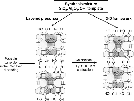
The above described practice of zeolite synthesis traditionally afforded microcrystalline products with completed 4-connected framework, which was not amenable to post-synthesis structural modification. This is most evident during the standard processing as the obtained crystals are being activated by ion exchange and calcination showing little or no apparent change of lattice parameters, which is readily ascertained based on the corresponding X-ray powder diffraction patterns. In general, no meaningful structure contraction, expansion or other non-destructive geometry modification have been observed or expected as the result of such processing.
New opportunities arose in conjunction with the discovery of zeolite MCM-22, which exhibited a new fundamental property of zeolite formation via layered precursor, designated MCM-22P (variations on this designation include MCM-22(P), MCM-22-P).10,11 In fact, the MCM-22 framework was found to form by two pathways as shown in Fig. 1: the mentioned indirect lamellar one and the traditional direct pathway. In contrast to the typical 3D zeolite frameworks assembled directly with no flexibility for modification, the layered precursor was viewed11 and demonstrated12 that it could be structurally modified after the synthesis. At the same time, the layered precursor versions of other frameworks were found, expanding the field to other zeolites, most notably some classical representatives like FER,13,14SOD,15–17 and recently MFI.18 Various forms like pillared and delaminated structures built from framework monolayers (components of the layered precursors) were being proposed and realized (see ref. 19). MCM-22 was leading the way in demonstrating novel types of layered structures, like pillared, delaminated and disordered layered precursor, summarized in ref. 20, which was expanding the number and diversity of structurally distinct materials based on the MWW structures, referred to as the MCM-22 family.
 | ||
| Fig. 1 Two pathways to zeolite MCM-22 framework (MWW). The structure on the right represents both the template containing MCM-49 as well as the final template-free calcined framework of both MCM-22 and MCM-49. | ||
The objective of this contribution is to provide up-to-date knowledge and challenges associated with “two-dimensional zeolites (2D zeolites)”, which herein means those having the third dimension limited to about 2–3 nm, thus, the dimension corresponding to 1–2 unit cells, and to discuss the capability to modify zeolites structurally to get new adsorbents and catalysts. The main difference in comparison with conventional zeolites stems from the fact that with 2D zeolites adsorption and catalysis occur almost exclusively on the surface of these materials and not inside the zeolite pores. The present publication outlines some practical benefits while at the same time discussing future prospects and opportunities. In addition, we focus on challenges associated with characterization of these novel materials, which requires systematic and meticulous approach for their synthesis and proper identification.
In this perspective we refer to (i) pillared materials—they have permanently expanded interlamellar distance/space caused by the presence of localized props (pillars) made of silica or other thermally stable substances. They are typically produced by initial intercalation of expanding/swelling organic substance followed by treatment and insertion of a soluble material that transforms into pillars upon burning off of the intercalant. (ii) Delaminated zeolites—separated into constituent layers, may be understood as any collection of zeolite layers that are not ordered, without alignment in the third direction, and ideally without any connections among the layers, except for incidental. (iii) Stabilized precursors (IEZ—interlamellar expanded zeolites)21,22 layered precursors with interlayer separation made permanent, e.g. by treatment with silylating agents. At present, around 10 zeolites (e.g. MWW, FER, Table 1) have a layered precursor known. The first comprehensive review of this emerging subject was published in 2007 and has not been updated since then.19
| Zeolite, calcined | Directly 3D assembled | Layered precursor | Pillared derivative | Delaminated | Stabilized precursor | Other |
|---|---|---|---|---|---|---|
| MWW | MCM-49 | MCM-22P | MCM-36 | ITQ-2 | IEZ-MWW | |
| MCM-22,-49 | MCM-56 |
| FER | Ferrierite | PreFer, PLS-3 | ITQ-36 | ITQ-6 | IEZ-FER | ERS-12 disordered |
|---|---|---|---|---|---|---|
| CDO | MCM-65, -47 | IEZ-CDO | ||||
| CDS-1 | PLS-1, -4 |
| CAS | CAS | EU-19 major | ||||
| EU-20b |
| NSI | NU-6(1) | MCM-39(Si) | ITQ-18 | EU-20 disordered | ||
| NU-6(2) | EU-19 minor |
| SOD | Sodalite | RUB-15 | ||||
|---|---|---|---|---|---|---|
| RWR | ||||||
| RUB-24 | RUB-18, -51, HLS |
| RRO | RUB-39 | |||||
| RUB-41 |
| AFO | AFO | PreAFO | ||||
|---|---|---|---|---|---|---|
| MFI | Yes | Yes | ||||
| ZSM-5 |
2. Synthesis of layered zeolite precursors
The first critical step towards entry into the area of modified precursors is the actual preparation and identification of a layered precursor or some other lamellar zeolite forms. Such syntheses occurred typically unexpectedly upon conventional organic templated preparations. They are usually recognized when the as-synthesized product changes XRD pattern upon calcination.11 New findings have been rare but recent discoveries of the layered precursors of frameworks have become more frequent.18,19 Generally speaking, the synthesis mixture compositions and conditions applied to date favoured direct framework assembly with 3D connectivity, i.e. afforded traditional zeolites. MWW formation may again provide some insights into alternative routes as it shows transition from direct to the lamellar pathway upon slight adjustment of the reaction mixture composition, namely the case of MCM-22P and MCM-49 synthesis.10,11 The family of MWW zeolites and related materials is presented in Fig. 2. A detailed analysis of the underlying reasons for the formation of MCM-22P and MCM-49 has not been considered in publications. It is evident that to achieve formation of a layered precursor the framework growth must be prevented from propagation in the third dimension. The end effect is the presence of silanol groups or their deprotonated moieties on the surface of the layers. This termination happens because of blockage by the template or other factors preventing sustainable attachment of another silicate tetrahedra or small units to that site. Further probe into what factors or maybe particular types of atoms do stabilize T–OH termination, may enable more designed approach to the synthesis of layered zeolite structures.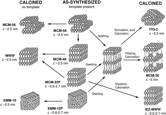 | ||
| Fig. 2 Updated MCM-22 ‘family tree’ illustrating proposed layer arrangements and synthesis pathways. | ||
The MWW framework has been, to date, arguably the major source of diversity and innovation in this area.20,21,23 It marks the advances in terms of new structures, fundamental insights and modified catalytic properties. MCM-22 was first to demonstrate formation of the 3D frameworks by 2 pathways, which is at the center of the 2D zeolite area. There are now 4 different MWW related materials known that were obtained by direct synthesis:20 3D structure (MCM-49), layered precursors (ordered MCM-22P and disordered EMM-10P) and delaminated (MCM-56). Fig. 3 provides comparison of X-ray powder patterns of these MWW materials obtained by direct synthesis. The modified derivatives include pillared MCM-36,12 delaminated ITQ-2,24 and stabilized precursors (IEZ).21 MWW family also sets the standard for identification of various types of materials (structure arrangements) by X-ray powder diffraction.20,23 Based on detailed analysis of positions and appearance of diffraction lines the procedure allows unambiguous identification of a particular structure (layer packing, distance and order) and even detection of mixtures.19 Regarding post-synthesis modification, XRD is invaluable in confirming the quality and extent of the intended transformation thus validating veracity of a particular procedure and sample structural characteristics. The MCM-22 family has been the template to follow in developing other layered families in terms of synthesis, identification and characterization.14,21
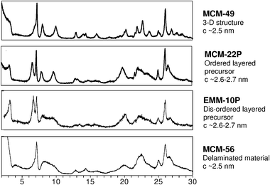 | ||
| Fig. 3 X-Ray powder patterns of various MCM-22 family materials obtained by direct synthesis. | ||
The recent lamellar MFI discovery (‘single-unit-cell nanosheets’) represents a very promising step-out change by providing a possible general approach to the synthesis of zeolitic lamellar precursors.18,25 It involves an SDA with one end designed to template the zeolite framework (in this case MFI) while the other end is a long chain preventing adjacent growth of another (connected) layer, simultaneously providing organic interlayer between the MFI monolayers. The overall effect is a direct synthesis of a hybrid structure, equivalent to a swollen product, with alternating inorganic and organic layers. These layers were reported to have 2.0 and 2.8 nm height, respectively based on TEM images. Identification also included XRD, which showed overall similarity to MFI but only h0l reflections were sufficiently distinct to enable indexing, i.e. assignment of (hkl) indices. This indication of short crystallographic order in the b-direction is consistent with the proposed hybrid structure. Removal of the template by calcination did not produce well ordered MFI, but the sample had a considerable mesoporosity, attributed to non-congruent collapse. A follow up publication reported dimension of the product somewhat differently with repeat 6.1 nm including 2.0 nm MFI layer and 4.1 nm organic part.25 It also claimed successful synthesis of the pillared derivative so we will continue discussion in the corresponding section 5.
Additional attractive feature of the MFI layers is the presence of perpendicular pores, which enable transport across, i.e. in three dimensions, through the crystal. Another material with pores across is AMH-3 with 8-ring apertures, which are, however, inaccessible for most of organic molecules.26 The sodalite precursor, designated RUB-15, did not condense into an ordered framework upon standard calcinations.15 However, if the template is first removed by extraction with acetic acid and then calcined an ordered condensed structure is obtained.16 Further on, refluxing RUB-18 with C16TMA (cetyltrimethylammonium) induced the formation of pores on the layer surfaces, though the mechanism is not well understood.27
FER and CAS layers afford 2 different zeolites each, FER and CDO, and CAS and NSI, respectively, which was attributed to the lack of mirror symmetry plane in the layer.28 Depending on the symmetry relationship between the layers, translation or reflection in mirror plane, different structures were produced. The chemical effects determining which layer orientation is adopted during the synthesis, are not known. Ferrierite sheets having no internal porosity can be templated by different SDAs depending on the synthesis conditions. Recent additions include PLS-3 and PLS-4 providing layered precursors of FER and CDO.29,30
Several layered zeolite precursors have been identified in the course of systematic work on templated silicate synthesis by Gies and co-workers, who designate their products with acronym RUB. Remarkably one of them turned out to be layered precursor of the well known framework SOD,15 which provided a convenient aqueous route to all siliceous sodalite. Other frameworks reported by this group are also notable as being obtained by the layered intermediate route only.31,32 The direct framework synthesis is expected but has not been observed yet. The group of Gies is also a leader in systematic and thorough structure determination33 and analysis of various layered precursors and has revealed valuable insights including structure of EU-20b, containing both NSI and CAS frameworks in one sample.34
The framework AFO, AlPO-41, was obtained both directly and from layered aluminophosphate precursor.35 The latter was obtained with a bulky macrocycle polyamine as the structure directing agent. The complete AFO topology required translation of alternate layers by 0.5a and 0.5b with condensation.
3. Expansion and swelling of the as-synthesized precursors
This has been historically the most difficult and critical step in modification of the precursors, which can be then delaminated and pillared. Again, MCM-22 provided the first published example12 indicating that it was a rather demanding treatment entailing the use of surfactant solution at high pH. The pitfalls are obvious now—there is a danger of silica solubilization, which is promoted by basic environment and possible formation of an M41S phase.36 The first successful swelling of MCM-22P was achieved with a surfactant hydroxide solution free from other cations, as the most common ones, like Na+ and tetramethylammonium, would diffuse preferentially into the interlayer space.37 It was subsequently established that it was possible to use a solution with potentially non-interfering cation supplying hydroxide ions together with a surfactant salt instead of the less desirable surfactant hydroxide. That cation had to be excluded by its size from competing for the interlayer space and tetrapropylammonium (TPAOH) was found suitable38 and commonly used since in swelling/delamination of other zeolite precursors.The relative complexity of swelling, its severity and potential undesirable reactions impose a special demand for verification that indeed the intended effect, i.e. swelling with no mesoporous MCM-41 or related phase formation, was realized. XRD is in general the adequate tool that can be used for that. As illustrated by the first case of MCM-22 some of the new features in the XRD patterns indicative of interlamellar expansion were not anticipated and needed validation by accumulation of evidence. The topic has been described in great detail12 and here we mention only the final conclusions. Successful swelling of MCM-22P can be proven based on two features, a low angle line, typically around 5 nm of d-spacing and transformation of the diffraction lines initially at 8 and 10° 2θ CuKα, into a broad band without a dip somewhere in between these two positions. At the same time the initial (002) reflection at the d-spacing ∼1.34 nm had to disappear completely.
As mentioned, the above synthetic procedure for swelling using surfactant with TPAOH has been used with other precursors. Recently, swelling of MCM-22P under milder conditions has been explored.39,60 It was concluded that swelling of MCM-22P at room temperature produced less degradation of the MWW layers and in the end translated into more ordered and catalytically active MCM-36 material.
4. Synthesis of delaminated materials
Delaminated, disordered forms of the following zeolites have been claimed and are designated as follows: MWW–ITQ-2,24MCM-56,23,40FER–ITQ-6,13 and NSI–ITQ-18.41 Except for MCM-56, all were obtained by firstly pre-swelling or by a treatment of the corresponding precursors with surfactant in the presence of TPAOH or other tetralkylammonium hydroxide sources.Exploitation of the synthetic opportunities of MCM-22P materials resulted in the preparation of delaminated ITQ-2 samples by Corma et al.24 The first step in the preparation of ITQ-2 was swelling of MCM-22P in the solution of hexadecyltrimethylammonium bromide and tetrapropylammonium hydroxide38 monitored by XRD. Delamination was performed by placing the slurry in an ultrasound bath under controlling pH. While the thickness of the layers is 2.5 nm their distance increased to 4.3 nm after the swelling step. After calcination, a system of accidentally oriented layers (“house of cards”) is produced. Analogy with MWW structure and TEM study revealed that the surface consists of 0.7 × 0.7 nm cups and the 10-ring channel system in the layer between them. Concentration and particularly location of aluminium in the cups vs.channel system is critical for their catalytic application. The benefits of easier site accessibility and shorter diffusion paths in ITQ-2 resulted in higher cracking conversions of n-decane, 1,3-diisopropylbenzene, and vacuum gas oil over ITQ-2 when compared with the non-delaminated MWW zeolite. The authors indicated the danger of surfactant-assisted mesoporous phase formation, e.g. if temperature during sonication is elevated above 50 °C.42 Related studies concluded that efficiency of ITQ-2 production is better at higher Si/Al ratio.43 This study also showed significant dissolution of the MWW layers and consequent diminished yield of the solid product.
In continuation of this research, ITQ-6—the delaminated form of FER, was prepared again by the group of Corma14 from PreFER.13 For the preparation of PreFER (or FER-P), 4-amino-2,2,6,6-tetramethylpiperidine was used instead of pyridine, piperidine or other templates usually used for the direct synthesis of 3D FER. Further treatment of PreFER resembles that for the synthesis of ITQ-2. It could be inferred that the addition of four methyl groups to piperidine is important for blocking of the stacking of the individual FER layers and enables the post-synthesis treatment, FER-P to ITQ-6.
MCM-56 deserves a special consideration as the only apparently delaminated zeolite to date obtained spontaneously in the course of a standard hydrothermal synthesis.23,40 This represents a convenient entry to delaminated materials with enormous advantage in cost and labour for further experimentation (treatments). The synthesis is somewhat more demanding than the conventional zeolite preparation because the MCM-56 is an intermediate that must be intercepted at the right moment before the onset of slow conversion to the ordered structure MWW (MCM-49) with layer stacking in 3D. This can be judged based on XRD pattern. The presence of a dip in the broad band spanning the 8–10° 2θ region, suggesting separation into two peaks, indicates MCM-56 is past its optimal point and the formation of ordered 3D MWW structure began (Fig. 4). Detailed guidance for distinguishing different members of the MWW family can be found in a recent publication.44
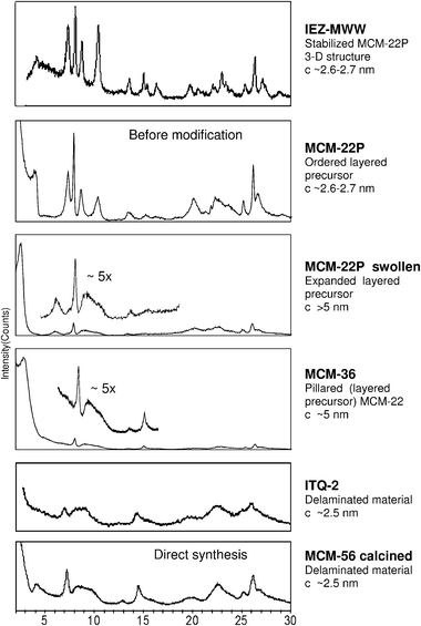 | ||
| Fig. 4 X-Ray powder patterns of various MCM-22 family materials obtained by modification of MCM-22P. MCM-22P and MCM-56 patterns included for comparison. | ||
An XRD pattern resembling that of MCM-56, specifically a broad band at 8–10° 2θ and no diffraction line with hkl indexes (002) at 6.5 2θ has been generated from MCM-22P by treatment with acetone45 and acid.46 The corresponding materials are probably different from MCM-56 by still retaining extensive hydrogen bonding between layers that is originally present in MCM-22P. As discussed20 this bonding does not require orientation perpendicular to MWW and can result in layers twisting with the loss of vertical alignment. There may be a simple test of this hypothesis. Earlier only TPA-OH was shown to be effective as the hydroxide source in allowing swelling of MCM-22P with surfactant as it is too big to compete with the latter for entering the interlayer space, which would thwart swelling. The smaller quaternary ions, like tetra-methyl and ethyl, were found ineffective as themselves diffusing between the layers preventing surfactant migration (between the layers). As reported, MCM-56 can be swollen in the presence of TMA,19 which is much smaller than TPA, indicating a free access to its surface and suggests absence of adjacent layers connected by interlayer H-bonding. These are intriguing basic issues that may be undertaken in future research.
In addition to the three already mentioned MWW materials obtained by direct synthesis in the 1990's, a new one, designated EMM-10P, apparently missing on theoretical grounds, has been identified recently.20a The identification is based on unprecedented XRD combining features of the MCM-22P and MCM-56. The pattern has a doublet at 6.5–7.2° 2θ, i.e. indicating expanded layered structure, and a broad band spanning ca. 8–10° 2θ indicative of lateral disorder, i.e. non-aligned stacking. The nature of the disorder has not been determined but has been tentatively proposed as having MCM-22P stacking with layers twisted in-plane or mismatched laterally but with preservation of interlayer hydrogen bonding through silanols. EMM-10P was obtained with a diquaternary template, bis(N,N,N-trimethyl)-1,5-pentanediaminium, Diquat-C5, which may span the adjacent layers.
The delaminated derivative of zeolite NSI, ITQ-18 was obtained from the long-known material NU-6(1) based on the 4,4′-bipyridine template.47 The as-synthesized layered precursor containing the template was treated with a mixture of surfactant and TPA-OH and then subjected to standard delamination procedure. Subsequent work48 led to conclusion that: ‘recipe…may lead to materials with high specific areas but, which not necessarily must have the characteristic long-range ordering of crystalline ITQ-18’.
In somewhat related work, acid treatment of NU-6(1) resulted in template removal and then the product, MCM-39, was reacted with the surfactant hydroxide to accomplish swelling. The final treatment was transformation into the pillared product MCM-39(Si).49
In general terms, delaminated zeolites are a rapidly growing area. There is not enough accumulated information and validated physical data yet to predict the range of properties and behaviour to be expected. The problem of proper identification is of crucial importance. There is an expectation of structural disorder and implied difficulty with reliability on the traditional XRD, which is very powerful with regular zeolites. In fact, an apparently delaminated material MCM-56 (vide supra) shows that XRD may be quite revealing about the nature of the product and the extent of disorder but it does not convey information about structural properties in the third dimension.
5. Synthesis of pillared materials
The organic expanded interlayer space such as in swollen materials, can be transformed into permanent large pore (mesopore) system by the process called pillaring. It entails treatment with appropriate oxide precursor like liquid alkoxide, which partially fills the interlayer space. The swelling organic still left is subsequently removed upon calcination, which simultaneously generates solid oxide props from alkoxide keeping the layers apart. The treatment is not guaranteed to succeed, in which case the interlamellar space would collapse. An effective and often successful procedure uses treatment with TEOS followed by hydrolysis with water and final calcination.50 This generates amorphous silica between the layers, apparently concentrated in domains (pillars) while significant amount of void space remains. This procedure proved very effective for the hexadecyltrimethylammonium swollen MCM-22P yielding the first pillared zeolite based material MCM-36 containing interlamellar mesopores in addition to the layer microporosity.12 The amount of silica introduced was roughly equal to the amount of zeolite by weight, judged from changes in Si/Al ratio. The corresponding TEM of the calcined product shows MCM-22 layers equally spaced with roughly 2.5 nm thick region in between containing the pillars, which are not visible as amorphous and without long range periodicity. Successful pillaring for the entire sample was validated by extensive characterization including XRD, static and dynamic sorption measurements. A particular care was taken to prove that the XRD characteristics, like the low-angle line, and increased BET and sorption characteristics did not arise from accidentally produced mesoporous material of the M41S type. Pore size distribution obtained based on Ar adsorption indicated mesopores with maximum at 3–3.5 nm. MCM-36 also showed unique and valuable catalytic properties, which are discussed in the corresponding section below.The exact nature of the pillars, such as lateral dimensions, spacing and distribution (ordered, disordered) remain a mystery. The featureless appearance of interlamellar space in TEM (Fig. 5) of cross-sectioned crystals indicates lack of regularity and provides no further clue. The typical graphical representation of pillared materials as regular well shaped props is unlikely representative of real situation. The most general description can be that in between zeolite layers there is a layer of amorphous silica with channels, mainly of the size 2–3 nm, whether regular or not is unknown, but certainly allowing access to the surface pockets of MWW sheets.
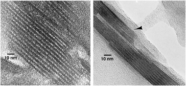 | ||
| Fig. 5 TEM images of calcined MCM-36 and MCM-22 showing permanent separation of the MCM-22 monolayers by pillaring. | ||
The very attractive layered MFI derivative announced recently18 was also subjected to the above pillaring treatment.25 The process was deemed successful and it was claimed that the generated pillars were not amorphous but also had the MFI structure concluded from TEM images. The regions identified as pillars appear commensurate with the adjacent layers. It results in a continuous regular pattern of apparent MFI pores suggesting congruent underlying structure extending vertically through several layers. As the first and clearly unexpected case of ‘crystalline pillars’ this result requires further validation, and presents intriguing possibilities for catalytic activity and structure stability.
Pillaring represents a kind of permanent layer separation, while as discussed above the pillar structure and distribution between layers can be generally characterized as disordered (except for the MFI claim25). The recent stabilization of MCM-22P in its expanded form by silylation21 may be viewed as discrete ordered pillaring. In fact, it provides the first example of ordered pillaring. It was initially demonstrated with Ti-MWW, as Ti-YNU-1,22 and subsequently extended to standard MWW and then other layered precursors.21 The net result of this process is a larger pore version of MCM-22, effectively with 12-ring channels between the layers vs. 10-ring in the conventional MWW. The connecting moiety is identified as Si(OH)2 with remaining 2 valences spanning adjacent MWW layers though the T1 sites.22,51
The pillaring procedures discussed above were carried out with silica reagents, which proved most convenient and effective to date. The corresponding pillaring reagents are liquids with possibly the right balance of reactivity towards organics, polymerization and hydrolysis. To date there is no control over the pillar distribution and size as the intercalated swelling substance seems to determine final interlayer porosity. These are clearly variables that may require fundamental studies.
Alternative pillar compositions have been explored including Al2O3, MgO–Al2O3, BaO–Al2O3, Al2O3–SiO2, MgO–Al2O3–SiO2, and BaO–Al2O3–SiO2 yielding new derivatives of MCM-36.52 Enhanced Lewis acidity was generated with aluminium oxide-containing pillars, while basic properties were introduced upon pillaring with alkaline earth oxide aluminates (MgO/BaO–Al2O3). These approaches represent promising methodology for tailoring acid–base properties of zeolitic catalysts.
6. Adsorption and catalytic opportunities
While pillared and delaminated materials exhibit large surface areas comparable with mesoporous materials not too many examples of their adsorption studies have appeared in the literature in contrast to the latter. This might be due to more complex synthetic procedures when related to easier and straightforward one-pot syntheses of mesoporous molecular sieves although some textural features of e.g.SBA-15 (surface roughness53) can limit application and understanding of adsorption on them. In contrast, catalytic studies are rather frequent evidencing some advantages over 3D zeolites.Mesoporous materials modified with different amines offer high capacities for CO2 adsorption.54 However, ITQ-6 (delaminated FER material) modified by different aminopropyl groups exhibits higher adsorption efficiency in the whole region of CO2 pressures, defined as the number of adsorbed CO2 molecules per one amine ligand.55 This could indicate that smooth surface of ITQ-6 layers is more adequate for the spreading of aminopropyl groups resulting in a higher adsorbed amount of CO2 per amine group.
In catalysis, the accessibility of large external surface of delaminated or pillared materials is crucial as most of the reactions over these catalysts would occur on the external zeolite surface. Delaminated or pillared catalysts with a large and well organized external surface of tiny zeolitic crystals allow accessibility of active sites for bulky organic molecules, which would be otherwise sterically restricted by the channel entrances of conventional zeolites.
While the entire area of modified layered zeolite structures is of general fundamental interest the ultimate practical goal is to gain advantage compared with the parent zeolite. In fact, in order to be a viable candidate for development beyond laboratory the benefits must be substantial to offset the cost and trouble associated with additional, often demanding processing steps. Improved performance relative to the parent zeolite may be also treated as evidence that the attempted modification has been indeed successful. This may be exemplified by MWW, which itself is a highly active zeolite, thus if attempted modification fails the product is still likely to exhibit high activity.
The evidence of catalytic enhancement upon pillaring of a zeolite was provided originally by MCM-36.56,57 It must be appreciated that in its original form it contains roughly 50% by weight of amorphous silica, which is inactive and in many processes, such as cracking, MCM-36 performance may appear like ‘diluted’ MCM-22. However, in some processes the superiority of MCM-36 was without any doubt. In the report by Schweitzer and van den Oosterkamp56 the published patent data were compiled to compare activity of several zeolites in olefin alkylation of isobutane, which is an important industrial process currently practised in the refineries with HF and sulfuric acid as catalysts. Zeolites are in general inferior to liquid acid catalysts in this process but MCM-36 showed good performance in particular with regard to resistance to deactivation as shown in Table 2. In contrast, MCM-22 activity was poor providing low yields and product quality. Evidently the expanded interlayer space offered advantages compensating the acid site dilution (less active zeolite and presence of amorphous silica pillars). The benefits of more open structure were revealed in a liquid phase ethylbenzene synthesis by MCM-56.58 The monolayer MCM-56 showed higher activity than the conventional 3D zeolites with analogous framework, MCM-22 and MCM-49.
| Catalyst | SiO2/Al2O3 | T/°C | Yield (wt/wt) | C8 (wt%) | Me3C5/Me2C6 | Octane # RON/MON | Stability/g alkylate per g catalyst |
|---|---|---|---|---|---|---|---|
| MCM-22, MCM-49 | < 20 | 150 | — | — | — | — | — |
| MCM-36 | >30 | 150 | 2.1 | 53 | 2.4 | 91–93 | 23 |
| Zeolite beta | 24–30 | 90 | 2.0 | 69 | 2.2 | 91–93 | 12.5 |
| Faujasite, EMT | 10–12 | 80 | 1.3–2.0 | 72–76 | 4.1–4.2 | 91–97 | 2.1–>4.8 |
| HF | n.a. | 32 | 2.0 | 90 | 7.6 | 94–97 | 100 |
| H2SO4 | n.a. | 7 | 2.0 | 81 | 6.4 | 94–96 | 8.7 |
m-Xylene transformation at 350 °C has been developed to estimate the activity and selectivity of the three pore systems in MCM-22 materials (sinusoidal channels, supercages and external cups).59 Compared with regular MCM-22, pillaring caused a great change in the distribution of the activity: only approximately 15% of m-xylene transformation occurred in the 10-ring intralayer pores in MCM-36vs. more than 70% in the parent MCM-22 sample. The rest, i.e. 85% of the activity of MCM-36 (30% in MCM-22) is attributed to surface pockets, which may be accessible to larger molecules.
Maheshwari et al.60 reported that a milder swelling and pillaring process prevents destruction of the material and improved retention of zeolitic layers. As a result, higher conversions of MCM-36 prepared at room temperature compared with those of high temperature treatment were achieved in vacuum gas–oil cracking and transformations of aromatics.
ITQ-2 prepared from MWW lamellar precursor and having surface areas larger than 700 m2 g−1, showed superiority over MWW and MCM-36 in vacuum oil cracking. ITQ-2 exhibited higher conversion and yield of gasoline than other catalysts and similar yield of diesel as MCM-36. ITQ-2 is also highly active in reaction leading to the preparation of fine chemicals. In particular, ITQ-2 was superior for dimethylacetals and tetrahydropyranylation of alcohols and phenols over zeolites BEA and MWW for bulky substrates.61 When small substrates were used similar conversions were achieved evidencing the similar role of acid sites in all materials. Steric exclusion of bulkier substrates, not accessing zeolite channels, made ITQ-2 favourable for these reactions. The yield of acetalization of 2-acetonaphthalene with propylene glycol increased in the order BEA (5%) < MWW (20%) < ITQ-2 (63%)61 (Scheme 1)
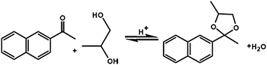 | ||
| Scheme 1 Reaction scheme of the formation of 2-methyl-2-naphthyl-4-methyl-1,3-dioxolane. | ||
The literature reports about catalytic activity of MCM-56 paint a somewhat inconsistent picture. Juttu and Lobo found their preparation to be largely inactive, which they attributed to coiling of the sheets observed in micrographs.62 A comparison between ITQ-2 and MCM-56 in large molecules conversion was reported to favour the former material.45 As mentioned above, MCM-56 appeared superior to MWW (MCM-22 and MCM-49) in liquid phase alkylation, which can be interpreted as advantage because of disordered/delaminated nature. The alkylation reactions studied in a gas phase led to the conclusion that the reactions proceed exclusively on the external surface of tiny MWW sheet crystals.63,64 This supports the superior catalytic activity of MCM-56, as this 2D zeolite exhibits much larger external surface. One must factor in the intermediate nature of MCM-56 during synthesis, which may cause isolation of product, either too early or too late and consequently not having the optimal performance.
Comparison of ITQ-2 and MWW modified with Mo was carried out by Martinez and co-workers65 for methane dehydroaromatization. ITQ-2 produced more naphthalene and less benzene than MWW. The selectivity to benzene was substantially improved by surface dealumination of the ITQ-2 zeolite with simultaneous decrease in naphthalene formation. Molecular dynamics simulation and treatment of the external surface evidenced the primary formation of naphthalene on the active sites located at the external surface of ITQ-2.65
Recently, Lima et al. reported on the preparation of delaminated zeolite derived from the layered material Nu-6(1).66 This delaminated catalyst exhibited conversion of about 80–85% in the liquid phase cyclodehydration of xylose to furfural with moderate furfural yields.
Relatively flat external surface of delaminated materials offers nice opportunity to attached organometallic complexes. ITQ-2 and ITQ-6 were studied also in Heck and Suzuki coupling reactions. In this case, Schiff base 2-tert-butyl-4-methyl-6{(E)-[(2S)-1-(1-arylmethyl)pyrrolidinyl] imino}methylphenol (aryl = phenyl, 1-naphthyl, 2-naphthyl) were used as anchoring ligands. After addition of Pd acetate high activity was achieved with recyclability and no leaching.67 Continuing this research, group of Corma immobilized mononuclear asymmetrical N-heterocyclic carbene-gold complexes on delaminated zeolite (ITQ-2). These complexes exhibit TOFs up to 400 h−1 in hydrogenations of alkenes and Suzuki coupling without dramatic deactivation.68 In another work zirconocenes Cp2ZrCl2 and (nBuCp)2ZrCl2 were grafted to the surface of delaminated and mesoporous supports. Although SBA-15 modified catalyst achieved the highest activities in polymerization ethylene, promising results were obtained also with MWW and ITQ-2 supports.69Polymerization reaction proceeded at the presence of methylalumoxane as co-catalyst.
Catalytic investigations of delaminated materials were extended to Ti-containing catalysts.70 Corma et al. demonstrated that Ti-ITQ-6 is highly active in hexene and norbornene epoxidation and this catalyst showed higher activity than Ti-FER or Ti-BEA. High stability of the conversion is due to exclusive tetrahedral coordination of Ti in the silica matrix, which was maintained even after the reaction.70 High activity of delaminated Ti-zeolites was confirmed for cyclooctene and cyclododecene by group of Tatsumi.71Zeolite MWW with titanium demonstrated exceptional activity as an oxidation catalyst and has been extensively studied since.72–74 The corresponding lamellar precursor form became attractive for modifications, previously discussed and implemented in practice, like delaminated and pillared forms. In fact, the first example of the precursor stabilized in the expanded form, now designated IEZ-MWW, was obtained in the Ti-MWW system and designated Ti-YNU-1.22 Its crystal structure was determined by Rietveld refinement.22 This material showed enhanced activity compared with other titanosilicates and attributed by the authors to ‘formation of twelve-rings…, which results in increased steric accessibility…’. Subsequently, attempts were made to swell Ti-MWW to synthesize delaminated and pillared derivatives. The former was reported to be superior to TS-1, Ti-Beta, conventional 3D Ti-MWW and Ti-MCM-41 in the epoxidation of a wide range of bulky alkenes with hydrogen peroxide.75Ti-MCM-36 synthesized by standard procedure was tested for 1-hexene and propylene epoxidation reactions using H2O2 as an oxidant and reported superior performance of Ti-MCM-36 over Ti-MCM-22 or TS-1.76 Both reports provided XRD patterns of the final catalysts but without analysis to verify layer packing.
Superior catalytic behaviour of delaminated and pillar zeolites in some acid and oxidation reactions is usually attributed to high surface areas of these catalysts and easy accessibility of the active sites on the external surface. Surface areas of external surface are at the range of 700–900 cm2 g−1 and are comparable with surface areas of mesoporous molecular sieves. Recent results of Gil et al. showed the invariance and homogeneity of the concentration of Brønsted sites on the external surface for the series of MCM-22 and MCM-49 with different Si/Al ratios.77
Combination of inorganic (zeolitic) layers with organic pillars represents another interesting approach to prepare active catalysts. Kuroda et al. showed that layered octosilicate can be treated with 1,4-bis(trichloro- and dichloromethyl-silyl) benzenes to prepare microporous inorganic–organic hybrids.78 They subsequently hydrolyzed the chlorosilane moieties and the resultant silanols were close enough to enable condensation into a Si–O–Si interlayer bridge. Very recently, a novel layered zeolitic organic–inorganic material (MWW-BTEB) has been reported by group of Corma79 combining intercalation and stabilization of arylic silsesquioxane molecules between inorganic zeolitic MWW layers. 1,4-Bis(triethoxysilyl)benzene (BTEB) was used as organic linker being aminated after the synthesis. The reported approach led to the of bifunctional acid–base catalysts exhibiting the acid sites of zeolitic nature combined with basic sites of the organic structure. This bifunctional catalyst was studied in a two-step cascade reaction that of benzaldehyde dimethylacetal into benzylidene malononitrile.79
7. Summary and challenges
Up-to-date, 10 frameworks have been recognized as having a layered precursor but not all among them have been prepared by both the direct (3D assembly) and indirect (layered precursor) synthesis pathway. More layered precursors are expected based on the fact that some long well-known conventional frameworks have been found only recently to have a lamellar form. Particularly encouraging is the case of MFI because of its 3D pore system. One may wonder if structures with isotropic distribution of density, i.e. the same in 3D, are also capable of showing layered precursors but we cannot point to a specific principle that may rule out lamellar forms for most, possibly all frameworks, as hypothesized earlier.23 The recent MFI case is also remarkable as apparently the first one where template was designed specifically for the purpose. In general, new precursors have been obtained accidentally thus availability of rational approaches is needed as it could facilitate further progress and directed expansion. In short, better understanding of factors affecting pathway selection for the framework or layer assembly would be very helpful. As the lamellar MFI provides layers with 10-ring channels through the layer it might be desirable to obtain layers with bigger channels like 12-ring and higher. This implies that precursors of zeolites like FAU, EMT or BEA would be highly valuable.Simultaneously, the area expands in terms of new layered architectures demonstrated. Here MCM-22 shows most diversity with 6 different types of layer assemblies, while the other frameworks are being gradually modeled on the known MWW materials. Aside from ‘standard’ layered precursor forms, MWW afforded rather unexpected remarkable materials spontaneously (MCM-56) or by post-synthesis modification (IZE-MWW). This suggests that additional structure types are possible and should be anticipated with enough effort and ingenuity. As the number of possibilities is increasing (different frameworks and layer packings) the attempts may become more selective with elements of design and focus on most promising precursors. It is easy to visualize ordered pillared materials with controlled pillar population and density, which would enable tailoring of large pore size of zeolitic structures.
In contrast to the framework rigidity and immutability, the lamellar forms offer the first and basically open-ended opportunity for post-synthesis modifications. The structural aspect has been already discussed in the paragraphs throughout this narrative. There is of course the option to use additional compositions, e.g. for pillars or other layer spacers, or just as deposits on the surface to modify properties. Delaminated materials may be made into mixtures with different layer topologies, as a fundamental option, but it may also turn out to offer practical benefits.
Another area of development may be the synthesis in terms of direct preparation without pre-swelling or at least without separation of intermediates of modified structures. Typically the modifications require several step procedures, which increases cost offsetting potential benefits offered by the more open structures. The only example to date is MCM-56, as the delaminated zeolite obtained in one step, suggesting other may be possible, too.
For now we know very little about the factors deciding whether the structure will propagate directly in 3D structure or terminate as a layer. As already suggested, MCM-22 and MCM-49 may provide the clue as they show the switch from one pathway to the other upon slight changes in composition. It was proposed19 that aluminium may play a significant role in this process but it is not well understood at this time.
Catalytic examples are rather broad covering area of cracking, some petrochemical applications up to synthesis of fine chemicals. Having in mind the structure of 2D zeolites and accessibility of active sites we do not expect some progress in shape-selective reactions as typical zeolite domain. In contrast, delaminated and pillared zeolite-based catalysts can offer high activities for transformations of bulky substrates or might be site-specific for reactions proceeding on the external surface of zeolite layers. On the other hand, the performance of MCM-36 in C4alkylation, i.e. resistance to deactivation, implies other benefits that may be possible with open architectures. It may be that in such cases retention of coke is not favored resulting in persistence of high activity.
Introduction of active metal sites (e.g.Al, Ti, Ga, Fe, etc.) in specific crystallographic sites is still a matter of vivid discussion in classical zeolites. Recently, Perez-Pariente and co-workers showed80,81 that controlled synthesis of FER can introduce aluminium exclusively to one crystallographic site. This evidences the potential of synthesis of zeolite catalysts with pre-defined catalytic activity and probably also selectivity, as one site might preferentially catalyze the reaction in the required way. As soon as this synthetic approach will be applied for other zeolites, particularly those prepared at first as layered precursors, it could be possible to obtain e.g. layered zeolitic precursors with or without any aluminium on the surface. This would open considerably the application potential of these zeolites.
Based on the knowledge and potential of zeolites numerous opportunities can be opened for 2D zeolites both from the fundamental as well as application point of view. Some of the challenges can be summarized as follows:
The most frequently studied lamellar precursors FER-P and MCM-22P lead by high-temperature treatment to tiny sheet zeolitic crystals. We wonder if there is any relationship between the final crystal shape of zeolites, their inner structure and the mechanism of the formation of a lamellar precursor. Successful syntheses of lamellar SOD zeolite provided clear evidence that even cubic zeolites can be prepared via their lamellar form.
Up to now, we know that active layers and non-active pillars can be prepared with a possible exception of MFI pillared materials (as discussed vide supra). Pure siliceous layers could be used to stabilize some highly active species in the form of pillars and in optimum way to control size and shape of the pillars and their catalytic activity.
Post-synthesis treatment of MWW by desilication has been recently reported attempting to connect two independent channel systems.82 For some catalytic applications it might be beneficial to form ordered channels (holes) in c-direction for delaminated (pillared) materials.
Last but not least, while the “synthesis–structure” relationships are mainly of a fundamental interest, the possible applications of 2D zeolites in adsorption, catalysis, sensing is extremely challenging. Optimization of catalytic performance with cost of large-scale production shall be targeted for industrial application.
Acknowledgements
J.Č. thanks the Academy of Sciences of the Czech Republic (KAN100400701) and the Grant Agency of the Czech Republic (104/09/0561 and 203/08/0604).References
- J. Čejka, H. van Bekkum, A. Corma and F. Schuth, Introduction to Zeolite Science and Practice, Stud. Surf. Sci. Catal., Elsevier, vol. 168, 2007 Search PubMed.
- R. Xu, W. Pang, J. Yu, Q. Huo and J. Chen, Chemistry of Zeolites and Related Porous Materials, Wiley, Singapore, 2007 Search PubMed.
- Molecular Sieves-Sience and Technology, ed. H. G. Karge and J. Weitkamp, Springer, Berlin, 1998, vol. 1 Search PubMed.
- (a) C. S. Cundy and P. A. Cox, Chem. Rev., 2003, 103, 663–701 CrossRef CAS; (b) C. S. Cundy and P. A. Cox, Microporous Mesoporous Mater., 2005, 82, 1–78 CrossRef CAS.
- L. A. Baumes, P. Serna and A. Corma, Appl. Catal., A, 2010, 381, 197–208 CrossRef CAS.
- (a) C. Baerlocher, W. M. Maier and D. H. Olson, Atlas of zeolite framework types, Elsevier, Amsterdam, 6th edn, 2007 Search PubMed; (b) http://www.iza-structure.org/default.htm .
- J. Čejka and B. Wichterlová, Catal. Rev. Sci. Eng., 2002, 44, 375–422 CrossRef CAS.
- J. L. Sun, C. Bonneau, A. Cantin, A. Corma, M. J. Diaz-Cabanas, M. Moliner, D. L. Zhang, M. R. Li and X. D. Zou, Nature, 2009, 458, 1154–1156 CrossRef CAS.
- J. Jiang, J. Yu and A. Corma, Angew. Chem., Int. Ed., 2010, 49, 3120–3145 CrossRef CAS.
- M. E. Leonowicz, J. A. Lawton, S. L. Lawton and M. K. Rubin, Science, 1994, 264, 1910–1913 CrossRef CAS.
- S. L. Lawton, A. S. Fung, G. J. Kennedy, L. B. Alemany, C. D. Chang, G. H. Hatzikos, D. N. Lissy, M. K. Rubin and H.-K. C. Timken, J. Phys. Chem., 1996, 100, 3788–3798 CrossRef CAS.
- W. J. Roth, C. T. Kresge, J. C. Vartuli, M. E. Leonowicz, A. S. Fung and S. B. McCullen, Stud. Surf. Sci. Catal., 1995, 94, 301–308 CrossRef CAS.
- (a) W. L. Schreyeck, P. Caullet, J. C. Mougenel, J. L. Guth and B. Marler, J. Chem. Soc., Chem. Commun., 1995, 2187–2188 RSC; (b) W. L. Schreyeck, P. Caullet, J. C. Mougenel, J. L. Guth and B. Marler, Microporous Mater., 1996, 6, 259–271 CrossRef CAS.
- A. Corma, U. Diaz, M. E. Domine and V. Fornes, J. Am. Chem. Soc., 2000, 122, 2804–2809 CrossRef CAS.
- U. Oberhagemann, B. Bayat, B. Marler, H. Gies and J. Rius, Angew. Chem., Int. Ed. Engl., 1997, 35, 2869–2872.
- T. Moteki, W. Chaikittisilp, A. Shimojima and T. Okubo, J. Am. Chem. Soc., 2008, 130, 15780–15781 CrossRef CAS.
- Y. Kiyozumi, T. Ikeda, Y. Hasegawa, T. Nagase and F. Mizukami, Chem. Lett., 2006, 35, 672–673 CrossRef CAS.
- M. Choi, K. Na, J. Kim, Y. Sakamoto, O. Terasaki and R. Ryoo, Nature, 2009, 461, 246–250 CrossRef CAS.
- W. J. Roth, Stud. Surf. Sci. Catal., 2007, 168, 221–240 CrossRef CAS.
- (a) W. J. Roth, D. L. Dorset and G. J. Kennedy, Microporous Mesoporous Mater. DOI:10.1016/j.micromeso.2010.10.052; (b) W. J. Roth, T. Yorke, D. L. Dorset, M. Kalyanaraman, M. C. Kerby and S. C. Weston, US Pat. 2008/0027256 A1, 2000 Search PubMed.
- P. Wu, J. Ruan, L. Wang, L. Wu, Y. Wang, Y. Liu, W. Fan, M. He, O. Terasaki and T. Tatsumi, J. Am. Chem. Soc., 2008, 130, 8178–8187 CrossRef CAS.
- (a) W. Fan, P. Wu, S. Namba and T. Tatsumi, Angew. Chem., Int. Ed., 2004, 43, 236–240 CrossRef CAS; (b) W. Fan, P. Wu, S. Namba and T. Tatsumi, J. Catal., 2006, 243, 183–191 CrossRef CAS; (c) J. Ruan, P. Wu, B. Slater and O. Terasaki, Angew. Chem., Int. Ed., 2005, 44, 6719–6723 CrossRef CAS.
- W. J. Roth, Stud. Surf. Sci. Catal., 2005, 158, 19–26 CrossRef.
- A. Corma, V. Fornes, S. B. Pergher, T. L. M. Maesen and J. G. Buglass, Nature, 1998, 396, 353–356 CrossRef CAS.
- K. Na, M. Choi, W. Park, Y. Sakamoto, O. Terasaki and R. Ryoo, J. Am. Chem. Soc., 2010, 132, 4169–4177 CrossRef CAS.
- S. Choi, J. Coronas, J. A. Sheffel, E. Jordan, W. Oh, S. Nair, D. F. Shantz and M. Tsapatsis, Microporous Mesoporous Mater., 2008, 115, 75–84 CrossRef CAS.
- R. García, I. Díaz, C. Márquez-Álvarez and J. Pérez-Pariente, Chem. Mater., 2006, 18, 2283–2292 CrossRef.
- W. J. Roth and D. L. Dorset, Struct. Chem., 2010, 21, 385–390 CrossRef CAS.
- T. Ikeda, S. Kayamori and F. Mizukami, J. Mater. Chem., 2009, 19, 5518–5525 RSC.
- T. Ikeda, S. Kayamori, Y. Oumi and F. Mizukami, J. Phys. Chem. C, 2010, 114, 3466–3476 CrossRef CAS.
- (a) Y. X. Wang, H. Gies, B. Marler and U. Müller, Chem. Mater., 2005, 17, 43–49 CrossRef CAS; (b) Y. X. Wang, H. Gies and J. H. Lin, Chem. Mater., 2007, 19, 4181–4188 CrossRef CAS.
- B. Marler, N. Stroter and H. Gies, Microporous Mesoporous Mater., 2005, 83, 201–211 CrossRef CAS.
- V. V. Narkhede and H. Gies, Chem. Mater., 2009, 21, 4339–4346 CrossRef CAS.
- B. Marler, M. A. Camblor and H. Gies, Microporous Mesoporous Mater., 2006, 90, 87 CrossRef CAS.
- P. S. Wheatley and R. E. Morris, J. Mater. Chem., 2006, 16, 1035 RSC.
- W. J. Roth, J. C. Vartuli and C. T. Kresge, Stud. Surf. Sci. Catal., 2000, 129, 501–508 CrossRef CAS.
- W. J. Roth and J. C. Vartuli, Stud. Surf. Sci. Catal., 2002, 141, 273–279 CrossRef CAS.
- (a) C. T. Kresge, W. J. Roth, K. G. Simmons and J. C. Vartuli, U.S. Patent 5,229,341, 1993 Search PubMed; (b) W. J. Roth, Pol. J. Chem., 2006, 80, 703–708 CAS.
- S. Maheshwari, E. Jordan, S. Kumar, F. S. Bates, R. L. Penn, D. F. Shantz and M. Tsapatsis, J. Am. Chem. Soc., 2008, 130, 1507 CrossRef CAS.
- A. S. Fung, S. L. Lawton and W. J. Roth, Synthetic Layered MCM-56, Its Synthesis and Use, US Patent No. 5,362,697, 1994 Search PubMed.
- A. Corma, V. Fornes and U. Diaz, Chem. Commun., 2001, 2642–2643 RSC.
- A. Corma, V. Fornes, J. M. Guil, S. Pergher, T. L. M. Maesen and J. G. Buglass, Microporous Mesoporous Mater., 2000, 38, 301–309 CrossRef CAS.
- P. Frontera, F. Testa, R. Aiello, S. Candamano and J. B. Nagy, Microporous Mesoporous Mater., 2007, 106, 107–114 CrossRef CAS.
- W. J. Roth and D. L. Dorset, Microporous Mesoporous Mater. DOI:10.1016/j.micromeso.2010.11.007.
- A. Corma, U. Diaz, V. Fornes, J. M. Guil, J. Martinez-Triguero and E. J. Creyghton, J. Catal., 2000, 191, 218–224 CrossRef CAS.
- Y. Wang, Y. Liu, L. Wang, H. Wu, X. Li, M. He and P. Wu, J. Phys. Chem. C, 2009, 113, 18753–18760 CrossRef CAS.
-
T. V. Whittam, US Pat. 4
![[thin space (1/6-em)]](https://www.rsc.org/images/entities/char_2009.gif) 397825, 1983 Search PubMed.
397825, 1983 Search PubMed. - H.-L. Zubowa, M. Schneider, E. Schreier, R. Eckelt, M. Richter and R. Fricke, Microporous Mesoporous Mater., 2008, 109, 317–326 CrossRef CAS.
-
C. T. Kresge and W. J. Roth, US Pat. 5266541, 1993 Search PubMed.
- M. E. Landis, B. A. Aufdembrink, P. Chu, I. D. Johnson, G. W. Kirker and M. K. Rubin, J. Am. Chem. Soc., 1991, 113, 3189–3190 CrossRef CAS.
- J. Ruan, P. Wu, B. Slater, Z. Zhao, L. Wu and O. Terasaki, Chem. Mater., 2009, 21, 2904–2911 CrossRef CAS.
- J.-O. Barth, A. Jentys, J. Kornatowski and J. A. Lercher, Chem. Mater., 2004, 16, 724–730 CrossRef CAS.
- (a) A. Zukal, H. Šiklová and J. Čejka, Langmuir, 2008, 24, 9837–9842 CrossRef CAS; (b) C. J. Gommes, H. Friedrich, M. Wolters, P. E. de Jongh and K. P. de Jong, Chem. Mater., 2009, 21, 1311–1317 CrossRef CAS.
- (a) P. J. E. Harlick and A. Sayari, Ind. Eng. Chem. Res., 2007, 46, 446–458 CrossRef CAS; (b) V. Zeleňák, M. Badaničová, D. Halamová, J. Čejka, A. Zukal, N. Murafa and G. Goerigk, Chem. Eng. J., 2008, 144, 336–342 CrossRef CAS.
- A. Zukal, I. Dominguez, J. Mayerová and J. Čejka, Langmuir, 2009, 25, 10314–10321 CrossRef CAS.
- E. J. A. Schweitzer and P. F. van den Oosterkamp, Microporous Mesoporous Mater., 1998, 20, 393.
- Y. J. He, G. S. Nivarthy, F. Eder, K. Seshan and J. A. Lercher, Microporous Mesoporous Mater., 1998, 25, 207 CrossRef CAS.
-
J. C. Cheng, A. S. Fung, D. J. Klocke, S. L. Lawton, D. N. Lissy, W. J. Roth, C. M. Smith and D. E. Walsh, US Pat. 5453554, 1995 Search PubMed.
- S. Laforge, P. Ayrault, D. Martin and M. Guisnet, Appl. Catal., A, 2005, 279, 79–88 CrossRef CAS.
- S. Maheshwari, C. Martinez, M. T. Portilla, F. J. Llopis, A. Corma and A. Tsapatsis, J. Catal., 2010, 272, 298–308 CrossRef CAS.
- M. A. Climent, A. Corma and A. Velty, Appl. Catal., A, 2004, 263, 155–161 CrossRef CAS.
- G. G. Juttu and R. F. Lobo, Microporous Mesoporous Mater., 2000, 40, 9–23 CrossRef CAS.
- J. Čejka, A. Krejčí, N. Žilková, J. Kotrla, S. Ernst and A. Weber, Microporous Mesoporous Mater., 2002, 53, 121–133 CrossRef CAS.
- A. Corma, V. Martinez-Soria and E. Schnoeveld, J. Catal., 2000, 192, 163 CrossRef CAS.
- A. Martinez, E. Peris and G. Sastre, Catal. Today, 2005, 107–108, 676–684 CrossRef CAS.
- S. Lima, M. Pillinger and A. A. Valente, Catal. Commun., 2008, 9, 2144–2148 CrossRef CAS.
- C. Gonzalez-Arellano, A. Corma, M. Iglesias and F. Sanchez, Adv. Synth. Catal., 2004, 346, 1758–1764 CrossRef CAS.
- A. Corma, E. Gutiérrez-Puebla, M. Iglesias, A. Monge, S. Pérez-Ferreras and F. Sánchez, Adv. Synth. Catal., 2006, 348, 1899–1907 CrossRef CAS.
- F. Silveira, C. F. Petry, D. Pozebon, S. B. Pergher, C. Detoni, F. C. Stedile and J. H. Z. dos Santos, Appl. Catal., A, 2007, 333, 96–106 CrossRef CAS.
- A. Corma, U. Diaz, M. E. Domine and V. Fornes, Chem. Commun., 2000, 137–138 RSC.
- P. Wu and T. Tatsumi, Chem. Commun., 2002, 1026–1027 RSC.
- A. Wróblewska, A. Fajdek and E. Milchert, Pol. J. Chem. Technol., 2009, 11, 64–71 Search PubMed.
- T.-K. Kim, S.-T. Yang, D. R. Park, I. K. Song, K.-E. Jung and W.-S. Ahn, Top. Catal., 2010, 53, 470–478 CrossRef CAS.
- W. Fan, P. Wu and T. Tatsumi, J. Catal., 2008, 256, 62–73 CrossRef CAS.
- P. Wu, D. Nuntasri, J. Ruan, Y. Liu, M. He, W. Fan, O. Terasaki and T. Tatsumi, J. Phys. Chem. B, 2004, 108, 19126–19131 CrossRef CAS.
- S.-Y. Kim, H.-J. Ban and W.-S. Ahn, Catal. Lett., 2007, 113, 160–164 CrossRef CAS.
- B. Gil, B. Marszalek, A. Micek-Ilnicka and Z. Olejniczak, Top. Catal., 2010, 53, 1340–1348 CrossRef CAS.
- D. Mochizuki, S. Kowata and K. Kuroda, Chem. Mater., 2006, 18, 5223–5229 CrossRef CAS.
- A. Corma, U. Diaz, T. Garcia, G. Sastre and A. Velty, J. Am. Chem. Soc., 2010, 132, 15011–15021 CrossRef CAS.
- A. B. Pinar, C. Marquez-Alvarez, M. Grande-Casas and J. Perez-Pariente, J. Catal., 2009, 263, 258–265 CrossRef CAS.
- L. Gomez-Hortiguela, A. B. Pinar, F. Cora and J. Perez-Pariente, Chem. Commun., 2010, 46, 2073–2075 RSC.
- A. van Miltenburg, J. Pawlesa, A. M. Bouzga, N. Žilková, J. Čejka and M. Stöcker, Top. Catal., 2009, 52, 1190–1202 CrossRef.
Footnote |
| † Permanent address: 123 Boundbrook Ct., Sewell, NJ, USA. |
| This journal is © The Royal Society of Chemistry 2011 |