A subtle interplay of C–H hydrogen bonds in complexation of anions of varied dimensionality by a nitro functionalized tripodal podand†
Sandeep Kumar
Dey
,
Bimlesh
Ojha
and
Gopal
Das
*
Department of Chemistry, Indian Institute of Technology Guwahati, Assam, 781 03, India. E-mail: gdas@iitg.ernet.in; Fax: +91-361-258-2349; Tel: +91-361-258-2313
First published on 7th September 2010
Abstract
The structural aspects of binding of halides (1 and 2), nitrate (3), perchlorate (4), trifluoroacetate (5) and hexafluorosilicate (6) with the protonated tripodal podand L are examined crystallographically. Anion binding with multiple receptor units is attributable entirely to the (NH)+⋯anion and multiple C–H⋯anion hydrogen bonding interactions in all six complexes. Protonation at the apical nitrogen and presence of nitro functionality renders the methylene and aryl hydrogen sufficiently acidic for their active participation in moderate to weak CH⋯anion interactions are noteworthy. All supramolecular networks of complexes 1–6 are guided by various non-convalent interactions, especially directional CH⋯Onitro hydrogen bonds and π-stacking interactions.
Introduction
Anion binding by synthetic receptors is an important and contemporary aspect of supramolecular chemistry and has proven its roles in biological systems, in environmental issues, and in the area of medicine and catalysis.1,2 The objective of achieving strong anion binding by hydrogen bonding receptors is an engaging challenge because of the design difficulties associated with targeting such large size and variably shaped, relatively diffuse, weakly basic, highly solvated analytes and interact with receptors only through weak forces.1a,3 Synthetic receptors have involved either hydrogen bonding alone (in neutral hosts), or a combination of hydrogen bonding and electrostatic interactions (in cationic hosts) for anion complexation.4 Recently, Bowman-James has categorized the binding of anions based on their coordination numbers which is helpful in defining the notions of complementarity for a given anion and can aid to the design of optimal anion-binding host structures.5 The most effective way to bind anions consist in taking advantage of their negative charge, and accordingly, polyammonium (positively charged) ligands have been the principal receptor of choice, since they ensure an adequate electrostatic attraction reinforced by hydrogen-bond contacts with the coordinated anions.6,7 Whereas the binding of anionic guests within pre-organized macrocyclic systems are relatively straightforward to understand but the binding processes of flexible podand receptors remain more elusive.8As anions display a wide range of geometries, the directionality of hydrogen bonds is frequently utilized to achieve complementarity between anions and receptors. Most hydrogen bonding anion receptors utilize N–H⋯anion or O–H⋯anion hydrogen bonds and C–H⋯anion hydrogen bonds are rarely utilized for anion binding even though C–H⋯anion hydrogen bonds play an important role in nature and thus, are drawing increasing attention among researchers.9 Although not typically considered to be significant donors, there is increasing evidence that C–H groups can participate in bonding and lead to enhanced anion-binding affinity.10 This evidence comes in the form of direct observation of close contacts in crystallographic structures,11 anion-induced chemical shifts of C–H protons in NMR spectra12 and theoretical calculations.13Imidazolium groups have already been introduced as anion binding hydrogen bond moieties by forming a (C–H)+⋯anion ionic hydrogen bond between C(2)–H in the imidazolium ring and the guest anion.14 The binding ability of tripodal receptors for anions varies with the attached functionality to the tripodal unit, since functional groups modify the hydrogen-bonding capability. Recent theoretical investigation by Hay et al. showed that the effect of electron withdrawing substituents on the aryl moiety significantly enhances the stability of anion complexes.15 A recent review of anion-arene adducts noted that aryl C–H⋯anion hydrogen bonding, rather than interaction with the π system, is by far the most prevalent motif observed in the solid state for the interaction of anion with arenes.16 Electronic structure calculations further probe the structural and energetic aspects of aliphatic C–H⋯anion hydrogen bonding confirming that the aliphatic C–H hydrogen bond is a viable interaction motif for anion host design.17
Some of our main concerns have been to ascertain the complexation and recognition of anion in the solid-state and the consequences of weak hydrogen bonding in the intermolecular network structure.18 Given our interest in structural aspects of anion binding, we have extensively studied the coordination of a cationic nitro functionalized tripodal podand, L (Scheme 1) with anions of different shapes and geometry. However, we have recently reported three conformational polymorphs of L obtained solely from traditional solvent mediated crystallization.23a Our discovery of the significant binding between different anions and protonated form of L is attributable entirely to the electrostatic (N–H)+⋯anion hydrogen bond and aliphatic as well as aromatic CH⋯anion interactions that presented a means of participating in the re-examination of the role of weak C–H hydrogen bond donors. Attempts were made to provide solid-state structural evidence for anion complexation by setting up a series of crystallization experiments of L with different anions. Herein, we report the solid state evidence for binding of chloride, bromide (spherical), nitrate (trigonal planar), perchlorate (tetrahedral), trifluoroacetate and hexafluorosilicate (octahedral) with protonated form of the podand L and their detailed molecular interactions.‡
![Structure of tris-[4-(nitrophenyloxy)-ethyl]-amine (L).](/image/article/2011/CE/c0ce00316f/c0ce00316f-s1.gif) | ||
| Scheme 1 Structure of tris-[4-(nitrophenyloxy)-ethyl]-amine (L). | ||
Experimental
Materials and methods
All reagents were obtained from commercial sources and used as received. Solvents were purified freshly following standard procedure prior to use. NMR spectra were recorded on a Varian FT-400 MHz instrument. The chemical shifts were recorded in parts per million (ppm) on the scale using tetramethylsilane (TMS) as a reference. Elemental analyses were carried out on a Perkin-Elmer 2400 automatic carbon, hydrogen and nitrogen analyzer.X-Ray crystallography
The intensity data were collected using a Bruker SMART APEX-II CCD diffractometer, equipped with a fine focus 1.75 kW sealed tube Mo-Kα radiation (λ = 0.71073 Å) at 298(2) K, with increasing ω (width of 0.3° per frame) at a scan speed of 3 s per frame. The SMART software was used for data acquisition. Data integration and reduction were undertaken with SAINT and XPREP19 software. Multi-scan empirical absorption corrections were applied to the data using the program SADABS.20 Structures were solved by direct methods using SHELXS-9721a and were refined by full-matrix least squares on F2 using SHELXL-9721b program package. In all the six compounds, non-hydrogen atoms were refined anisotropically. Hydrogen atoms attached to all carbon atoms were geometrically fixed while the hydrogen atom of tertiary amino nitrogen of the salts was located from the difference Fourier map, and the positional and temperature factors are refined isotropically. However, we were unable to locate the hydrogen atoms of the disordered lattice water molecules (O28, O29 and O30) in complex 6, from the difference Fourier map. Structural illustrations have been generated using ORTEP-322a and MERCURY 1.322b for Windows.Ligand design and synthesis
For a receptor to bind with the anionic guests, it should possess pre-organized anion binding elements decorated on the suitable platform/framework. Numerous synthetic anion receptors containing polyammonium, amide, urea/thiourea, pyrrole or indole groups incorporated in increasingly complicated supramolecular skeletons target the efficiency of natural receptors. However, our idea in designing and synthesizing receptor L for binding of different anions is principally because of the absence of conventional N–H or O–H hydrogen bonding functions for anions so that we could examine the involvement of weak C–H hydrogen bond donors toward binding of anions with the protonated form of the podand. Calculations on C6H6-anion complexes have shown that the aryl C–H donors are effective anion binding groups compared to aliphatic C–H donors.17 The strength of an aryl C–H donor group can in theory, be adjusted through the addition of different functional groups on the arene ring. It has been well established that the electron-withdrawing substituent on the benzene ring assist the active participation of the aryl –CH protons toward anion bindingvia C–H⋯anion interactions. Moreover, protonation at the apical nitrogen in L could significantly enhance the acidity of the aliphatic –CH2hydrogen and thereby, could possibly form moderate to weak C–H⋯anion hydrogen bonds perhaps of similar strength to aryl C–H⋯anion hydrogen bond. Considering the above points, we have designed and synthesized tripodal podand receptor L having nitro-substituted aryl terminals for anion binding studies.The acyclic tripodal receptor L has been synthesized by modification of known literature procedure.23 Complexes 1, 2, 3, 4, 5 and 6 were obtained by stirring a solution of L (50 mg) in 20 mL of methanol in a glass beaker and adding 1.2 equiv. of 37% HCl, 49% HBr, HNO3, 70% HClO4, CF3COOH and 40% HF, respectively. After a constant stirring for half an hour a solid precipitate was formed which was then filtered, washed with ether and dried under vacuum. Single crystals suitable for X-ray diffraction analysis were obtained from slow evaporation of CH3OH–CH3CN (1![[thin space (1/6-em)]](https://www.rsc.org/images/entities/char_2009.gif) :1) binary mixture solution of the compounds at RT within 1–2 weeks.
:1) binary mixture solution of the compounds at RT within 1–2 weeks.
:1) solution of the compound at RT for twenty days. 1H-NMR (400 MHz, DMSO-d6) δ 4.45 (s, 6 H, OCH2), 7.12–7.14 (d, 6 H, ArH), 8.18–8.21 (d, 6 H, ArH); 13C-NMR (100 MHz, DMSO-d6) δ 53.79 (×3C, NCH2), 67.00 (×3C, OCH2), 115.35 (×3C, Ar), 125.57 (×6C, Ar), 135.12 (×3C, Ar), 151.37 (×6C, Ar). Anal. calcd (%) for C24H27F3N4O10Si0.5: C 47.84, H 4.51, N 9.29%. Found: C 48.42, H 4.36, N 8.83%.
Results and discussion
Crystal structure studies
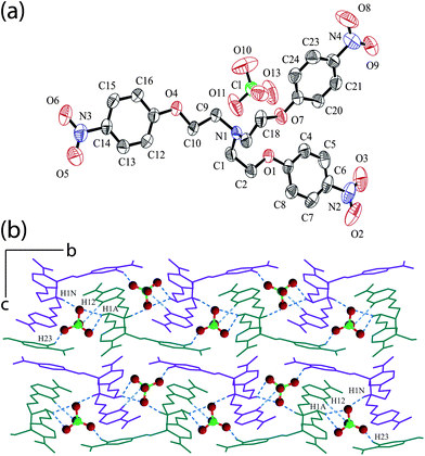
Structural information obtained from single-crystal X-ray analysis of the anionic complexes (1–6) can provide insight into the proper binding topology of anions with the protonated tripodal podand receptor. Crystal structure analyses revealed that the six crystals belong to the lower-symmetry monoclinic and triclinic crystal systems. Complexation of different anions by tripodal receptor L is primarily governed by two different types of supramolecular interactions. In all complexes, the exo-oriented hydrogen of the protonated tertiary nitrogen of the ligand is involved in a comparatively strong electrostatic (N–H)+⋯anion interaction. In addition to (N–H)+⋯anion interaction, the anions are further involved in several C–H⋯anion interactions with the alkyl and aryl hydrogen of the protonated podand satisfying the geometrical necessity of the flexible LH+ units to respond to the demand of the anions of different sizes and geometries. Thus, tripodal cations bearing nitro functions directed the anion assembly formation through a strong electrostatic hydrogen bond formation along with weaker noncovalent interactions.The chloride complex [HL+]·[Cl−] (1) crystallizes in triclinic space groupP![[1 with combining macron]](https://www.rsc.org/images/entities/char_0031_0304.gif) , with the tertiary nitrogen of the tripodal podand is protonated and turns out to be the monochloride salt of the podand. An ORTEP plot of 1 is shown in Fig. 1a along with the atom numbering scheme. The binding of chloride with encircling cations clearly demonstrates that each anion is involved in a seven-point attachment provided by three LH+ units with six C–H⋯Cl− contacts through an average C–H hydrogen bonding distance of 3.690 Å ranging from 3.601 to 3.821 Å and C–H⋯Cl angle range from 138 to 173° (Table 1). The close-up view of the hydrogen bonding interactions with the chloride ion is shown in Fig. 1b. The exo-oriented proton H1N of the protonated apical nitrogen is involved in (N–H)+⋯Cl− interaction with the anion with a hydrogen bonding distance of 3.013 Å and N–H⋯Cl angle of 160°. The methylene hydrogen H18A subsequent to the protonated nitrogen is C–H hydrogen bonded to Cl− with an interaction length of 3.633 Å. In addition, the aliphatic/aryl protons H2B, H9B and H4 from a different neighbouring cation make intermolecular C–H⋯Cl− contacts with the anion. Finally, the seven point-contacts on Cl− is fulfilled by the interactions from the aliphatic protons H9A and H17A of the third cation. The crystal packing motif viewed down the a-axis (Fig. 1c) clearly reveals that the receptor molecules beautifully pack in a bilayer array forming a hydrophobic chain of ligand moieties and the dimmers of chloride ions are entrapped between the adjacent bilayers generating a hydrophilic chain parallely along b-axis. Intermolecular C–H⋯Onitro hydrogen bonding between alkyl hydrogen H17B and nitro oxygen O5 (C17⋯O5 = 3.349 Å, < C17–H17B⋯O5 = 124°) is bridging the receptor moieties along b-axis. The adjacent monolayers of the ligand array are interconnected via C–H⋯π hydrogen bond formed between the aryl hydrogen H7 and phenyl ring involving carbon C11–C16 (C2g) forming the bilayers along b-axis (C7⋯C2g = 3.970 Å, < C7–H7⋯C2g = 157°). Expansion of a bilayer through hydrogen bonds suggests that, the bilayers are further interlinked among themselves via several C–H⋯Onitro interactions involving aliphatic/aryl protons (H2B, H10A H8, H16 and H20) and nitro oxygen atoms (O2, O3 and O6) in association with weak interligand π⋯π interactions (C1g⋯C1g = 4.183 Å; C3g⋯C3g = 3.610 Å; C1g⋯C3g = 3.858 Å) along a-axis whereas the hydrophilic anion chain stitches the adjacent bilayers along c-axis via multiple C–H⋯Cl− interactions generating overall a 3D hydrogen bonded network (Table S1, ESI).†
, with the tertiary nitrogen of the tripodal podand is protonated and turns out to be the monochloride salt of the podand. An ORTEP plot of 1 is shown in Fig. 1a along with the atom numbering scheme. The binding of chloride with encircling cations clearly demonstrates that each anion is involved in a seven-point attachment provided by three LH+ units with six C–H⋯Cl− contacts through an average C–H hydrogen bonding distance of 3.690 Å ranging from 3.601 to 3.821 Å and C–H⋯Cl angle range from 138 to 173° (Table 1). The close-up view of the hydrogen bonding interactions with the chloride ion is shown in Fig. 1b. The exo-oriented proton H1N of the protonated apical nitrogen is involved in (N–H)+⋯Cl− interaction with the anion with a hydrogen bonding distance of 3.013 Å and N–H⋯Cl angle of 160°. The methylene hydrogen H18A subsequent to the protonated nitrogen is C–H hydrogen bonded to Cl− with an interaction length of 3.633 Å. In addition, the aliphatic/aryl protons H2B, H9B and H4 from a different neighbouring cation make intermolecular C–H⋯Cl− contacts with the anion. Finally, the seven point-contacts on Cl− is fulfilled by the interactions from the aliphatic protons H9A and H17A of the third cation. The crystal packing motif viewed down the a-axis (Fig. 1c) clearly reveals that the receptor molecules beautifully pack in a bilayer array forming a hydrophobic chain of ligand moieties and the dimmers of chloride ions are entrapped between the adjacent bilayers generating a hydrophilic chain parallely along b-axis. Intermolecular C–H⋯Onitro hydrogen bonding between alkyl hydrogen H17B and nitro oxygen O5 (C17⋯O5 = 3.349 Å, < C17–H17B⋯O5 = 124°) is bridging the receptor moieties along b-axis. The adjacent monolayers of the ligand array are interconnected via C–H⋯π hydrogen bond formed between the aryl hydrogen H7 and phenyl ring involving carbon C11–C16 (C2g) forming the bilayers along b-axis (C7⋯C2g = 3.970 Å, < C7–H7⋯C2g = 157°). Expansion of a bilayer through hydrogen bonds suggests that, the bilayers are further interlinked among themselves via several C–H⋯Onitro interactions involving aliphatic/aryl protons (H2B, H10A H8, H16 and H20) and nitro oxygen atoms (O2, O3 and O6) in association with weak interligand π⋯π interactions (C1g⋯C1g = 4.183 Å; C3g⋯C3g = 3.610 Å; C1g⋯C3g = 3.858 Å) along a-axis whereas the hydrophilic anion chain stitches the adjacent bilayers along c-axis via multiple C–H⋯Cl− interactions generating overall a 3D hydrogen bonded network (Table S1, ESI).†
 | ||
| Fig. 1 (a) ORTEP plot (50% ellipsoids) of complex 1; (b) Close-up view of the seven hydrogen-bonding interactions of chloride anion (blue dotted lines) with three LH+ units; (c) Crystal packing diagram of complex 1 along bc-plane depicting the hydrophobic bilayer assembly formation of ligand moieties and hydrophilic anionic chain along b-axis. | ||
| D–H⋯A | d(H⋯A)/Å | d(D⋯A)/Å | ∠(DHA)/° |
|---|---|---|---|
| [HL+]·[Cl−] (1) | |||
| N1–H1N⋯Cl1 | 1.95 | 3.013 | 160 |
| C18–H18A⋯Cl1 | 2.85 | 3.633 | 138 |
| C2–H2B⋯Cl1 | 2.82 | 3.621 | 140 |
| C9–H9B⋯Cl1 | 2.84 | 3.684 | 145 |
| C4–H4⋯Cl1 | 2.89 | 3.821 | 173 |
| C9–H9A⋯Cl1 | 2.66 | 3.601 | 162 |
| C17–H17A⋯Cl1 | 2.92 | 3.780 | 148 |
| [HL+]·[Br−] (2) | |||
| N1–H1N⋯Br1 | 2.32 | 3.194 | 158 |
| C1–H1A⋯Br1 | 2.81 | 3.752 | 161 |
| C1–H1B⋯Br1 | 2.87 | 3.708 | 145 |
| C10–H10A⋯Br1 | 2.94 | 3.730 | 138 |
| C17–H17B⋯Br1 | 2.99 | 3.876 | 152 |
| C18–H18B⋯Br1 | 2.95 | 3.759 | 141 |
| C12–H12⋯Br1 | 2.96 | 3.894 | 173 |
| [HL+]·[NO3−] (3) | |||
| N1–H1N⋯O10 | 2.07 | 2.894 | 135 |
| N1–H1N⋯O11 | 1.89 | 2.881 | 160 |
| C1–H1A⋯O10 | 2.28 | 3.211 | 160 |
| C9–H9A⋯O11 | 2.46 | 3.184 | 131 |
| C10–H10A⋯O11 | 2.47 | 3.190 | 130 |
| C15–H15⋯O12 | 2.61 | 3.506 | 160 |
| [HL+]·[ClO4−] (4) | |||
| N1–H1N⋯O12 | 2.12 | 2.974 | 150 |
| C1–H1A⋯O10 | 2.43 | 3.240 | 140 |
| C1–H1A⋯O12 | 2.46 | 3.385 | 158 |
| C12–H12⋯O13 | 2.45 | 3.266 | 146 |
| C15–H15⋯O13 | 2.64 | 3.302 | 128 |
| C23–H23⋯O11 | 2.53 | 3.250 | 133 |
| [HL+]·[CF3COO−] (5) | |||
| N1–H1N⋯O10 | 2.60 | 3.248 | 120 |
| N1–H1N⋯O11 | 1.71 | 2.742 | 174 |
| C1–H1B⋯F2 | 2.56 | 3.487 | 158 |
| C1–H1B⋯O10 | 2.43 | 3.194 | 134 |
| C2–H2B⋯F3 | 2.65 | 3.529 | 150 |
| C2–H2B⋯O11 | 2.68 | 3.472 | 138 |
| C9–H9B⋯O10 | 2.51 | 3.055 | 115 |
| C4–H4⋯F2 | 2.63 | 3.086 | 110 |
| C7–H7⋯F1 | 2.44 | 3.306 | 154 |
| [2HL+]·[SiF62−]·2H2O (6) | |||
| N1–H1N⋯F1 | 2.41 | 3.118 | 135 |
| N1–H1N⋯F2 | 1.88 | 2.742 | 159 |
| N5–H2N⋯F8 | 1.96 | 2.756 | 168 |
| N5–H2N⋯F9 | 2.44 | 2.997 | 127 |
| N9–H3N⋯F4 | 2.55 | 3.217 | 125 |
| N9–H3N⋯F6 | 1.74 | 2.693 | 166 |
| C1–H1A⋯F1 | 2.58 | 3.081 | 111 |
| C1–H1B⋯F3 | 2.56 | 3.228 | 125 |
| C25–H25B⋯F2 | 2.46 | 3.218 | 134 |
| C25–H25B⋯F4 | 2.44 | 3.375 | 160 |
| C42–H42A⋯F4 | 2.42 | 3.211 | 138 |
| C44–H44⋯F3 | 2.66 | 3.487 | 147 |
| C44–H44⋯F4 | 2.57 | 3.441 | 155 |
| C49–H49A⋯F5 | 2.54 | 3.193 | 124 |
| C49–H49B⋯F4 | 2.63 | 3.157 | 114 |
| C57–H57B⋯F1 | 2.39 | 3.328 | 162 |
| C57–H57B⋯F6 | 2.51 | 3.178 | 126 |
| C58–H58B⋯F6 | 2.60 | 3.347 | 133 |
| C66–H66B⋯F4 | 2.52 | 3.340 | 142 |
| C33–H33B⋯F7 | 2.55 | 3.219 | 126 |
| C9–H9A⋯F8 | 2.37 | 3.230 | 146 |
| C9–H9A⋯F9 | 2.65 | 3.544 | 153 |
| C18–H18A⋯F9 | 2.49 | 3.293 | 140 |
| C20–H20⋯F9 | 2.48 | 3.366 | 159 |
| C33–H33A⋯F9 | 2.55 | 3.025 | 109 |
The bromide complex [HL+]·[Br−] (2) crystallizes in the lower symmetry triclinic space groupP with Z = 2. An ORTEP plot of 2 is shown in Fig. 2a along with the atom numbering scheme. In addition to ionic (N–H)+⋯Br− interaction (N⋯Br = 3.194 Å, <N–H⋯Br = 158°) similar to the chloride complex (1), there are six C–H⋯Br−hydrogen bonds from different alkyl and aryl hydrogen of the three coordinating tripodal units with an average hydrogen bonding distance of 3.786 Å ranging from 3.708 to 3.894 Å and C–H⋯Br angle range from 138 to 173° (Table 1). An unusual hepta-coordination in the halide complexes (1 and 2) suggests that the interactions with the C–H donors are too weak to impose a definite coordination structure around the bromide anions, and instead the CH groups on the flexible arms of the receptor embrace the anion so as to match its size and shape to provide a favourable electrostatic environment around it. In complex 2, the methylene hydrogen H18B subsequent to the protonated apical nitrogen is C–H hydrogen bonded to Br− while aliphatic protons H1A, H17B, H1B, H10A and aryl hydrogen H12 from two adjacent cationic units are making contacts to the anion intermolecularly via weak C–H⋯Br−hydrogen bonds. A close up view of the coordination of bromide anion by four cationic L units is depicted in Fig. 2b. Thus, the seven-point attachment via strong (N–H)+⋯Br− and weak C–H⋯Br− interactions is responsible for the binding and stabilization of the bromide ion with the protonated Lreceptor units. Moreover, there is marginal difference in the orientation of the tripodal arms on replacing chloride by bromide which is reflected in the torsion involving τamino (C–Namino–C–C) and τether (Namino–C–C–Oether) presumably due to the similar (seven-point contacts) coordination modes acquired by spherical bromide ion (Table S2, ESI).† The crystal packing diagram viewed down the a-axis (Fig. 2c) clearly shows that the receptor molecules beautifully pack in a bilayer array with two successive tripodal cations are flipped inward toward each other in a face to face fashion (dN1⋯N1 = 11.35 Å) and the bromide ions are trapped between the adjacent monolayers parallely along b-axis. Similar to 1, the cationic tripodal units are self assembled via six intermolecular C- H⋯Onitro interactions involving different C–H protons with one or both the oxygen from each nitro group, edge to face interaction and face to face interactions as well (Table S1, ESI).† Intermolecular C–H⋯Onitro hydrogen bonding between aryl hydrogen H24 and nitro oxygen O3 (C17⋯O5 = 3.349 Å, < C17–H17B⋯O5 = 124°) is bridging the receptor moieties along b-axis forming monolayers. The adjacent monolayers of the ligand array are interconnected via C–H⋯π hydrogen bond formed between the aryl hydrogen H15 and phenyl ring involving carbon C3–C8 (C1g) forming the bilayers along b-axis. Expansion through hydrogen bonds further reveals that, the bilayers are interlinked among themselves via multiple C–H⋯Onitro interactions and interligand π⋯π stacking (C3g⋯C3g = 3.610 Å; C2g⋯C3g = 3.858 Å) along a-axis whereas multiple C–H⋯Br− interactions stitches the adjacent bilayers along c-axis.
 | ||
| Fig. 2 (a) ORTEP plot (50% ellipsoids) of complex 2; (b) Close-up view of the seven hydrogen-bonding interactions of bromide anion (blue dotted lines) with three LH+ units; (c) Crystal packing diagram of complex 2 along bc-plane depicting the linear and parallel arrangement of the bromide anions trapped within the cationic tripodal arrays. | ||
Complex [HL+]·[NO3−] (3) crystallizes in monoclinic space groupP21/n with Z = 4. An ORTEP plot of 3 is shown in Fig. 3a along with the atom numbering scheme. The solid-state structure of complex 3 shows bifurcated (N–H)+⋯O interaction between the hydrogen of the protonated amine with the nitrate oxygen atoms O11 and O10 through N⋯O distances of 2.881 and 2.894 Å and N–H⋯O angle of 157 and 133° respectively. In addition, each nitrate ion is C–H hydrogen bonded with three encircling podand molecules with an average hydrogen bonding distance of 3.272 Å ranging from 3.184 to 3.506 Å and C–H⋯O angle range from 130 to 160° (Table 1). The nitrate oxygen O11 is involved in moderate aliphatic C–H⋯O interaction with the methylene hydrogen H17A and H18A of the same tripodal unit whereas O12 is in interaction with the methylene hydrogen H1A suggesting that O11 and O12 behaves as a trifurcated and bifurcated hydrogen bond acceptors respectively in the anion complex 3. In addition to the above five interactions, nitrate oxygen O10 is engaged in a comparatively weaker aryl C–H⋯O interaction with the aromatic proton H21 completing the sixth coordination contact of the nitrate anion. A close up view of the coordination of nitrate anion by four cationic L units is depicted in Fig. 3b. Each nitrate anion is held between the tripodal cleft shaped cavity genereted due to the folded conformation of two tripodal arms projecting in the similar direction by weak interactions. The packing diagram viewed down the crystallographic b-axis clearly shows that the cationic array of ligands is arranged diagonally along the ac-plane with the anions being situated in a zig-zag fashion between the cationic tripodal arrays (Fig. 3c). The cationic ligand moieties are self-organized via seven intermolecular C–H⋯Onitro hydrogen bonds between different aliphatic and aromatic hydrogen atoms with one or both the oxygen from each nitro group where O3, O5 and O6 behaves as bifurcated hydrogen bond acceptor (Table S1, ESI).†
 | ||
| Fig. 3 (a) ORTEP plot (50% ellipsoids) of complex 3; (b) Close-up view of nitrate binding depicting the six hydrogen-bonding interactions of nitrate anion (green dotted lines) with four cationic receptor units; (c) Crystal packing diagram of complex 3 along ac-plane depicting the zigzag arrangement of the nitrate anions diagonally along the ac-plane. | ||
Complex [HL+]·[ClO4−] (4) crystallizes in monoclinic space groupP21/c with Z = 4. An ORTEP plot of 4 is shown in Fig. 4a along with the atom numbering scheme. Similar to the halide complexes, there exists (N–H)+⋯anion interaction between the hydrogen H1N of the apical nitrogen and O12 of perchlorate (N1⋯O12 = 2.974 Å, < N1–H⋯O12 = 150°). In addition, there are five intermolecular C–H⋯O hydrogen bonds formed between the oxygen atoms of perchlorate anion and different alkyl and aryl hydrogen of the three neighbouring receptor units surrounding the anion (Fig. S5, ESI)† with an average C–H⋯O hydrogen bond distance of 3.288 Å and C–H⋯O angle range from 128 to 158°. The methylene hydrogen H1A of a tripodal unit is engaged in bifurcated C–H hydrogen bonding to O10 and O12 of perchlorate anion and O13 is involved in bifurcated acceptor C–H⋯O interaction with the aromatic hydrogen H12 and H15 from two different receptor units. The six-point contact of perchlorate anion is finally satisfied by the interaction between aromatic hydrogen H23 with the perchlorate oxygen O11. The details of these interactions are provided in Table 1. The overall non-covalent interactions with the anion results in the formation of a zipper like assembly when viewed down the crystallographic a-axis with the anions being arranged in a zigzag fashion stitching the adjacent cationic arrays by C–H⋯O hydrogen bonds along b-axis (Fig. 4b). The cationic L moieties are cross linked among themselves exclusively via six C–H⋯Onitro interaction between different alkyl and aryl hydrogen with one or both the nitro oxygen atoms among which O3 behaves as bifurcated hydrogen bond acceptor (Table S1, ESI).†
 | ||
| Fig. 4 (a) ORTEP plot of complex 4. (b) Crystal packing diagram of complex 4 viewed down the a-axis showing the formation of zipper-like assembly and hydrogen bonding interactions of perchlorate anion (blue dotted lines) with adjacent cationic receptor molecules. | ||
Complex [HL+]·[CF3COO−] (5) crystallizes in triclinic space groupP with Z = 2. An ORTEP plot of 5 is shown in Fig. 5a along with the atom numbering scheme. The binding of CF3COO− clearly shows that each trifluoroacetate ion is coordinated to five receptor units by a nine point attachment involving both oxygen and fluorine atoms of the anion. A close-up view for binding of trifluoroacetate anion has been provided in the supplementary information (Fig. S7, ESI).†Hydrogen H1N of the protonated apical nitrogen is in bifurcated (N–H)+⋯O interaction with O10 and O11 (N1⋯ O10 = 3.248 Å, <N1–H⋯O10 = 124°; N1⋯O11 = 2.742 Å, <N1–H⋯O11 = 174°) as observed in the nitrate complex. Methylene hydrogen H9B from the same cation is involved in the formation of moderately strong aliphatic C–H⋯O hydrogen bond with O10 of the anion (C9⋯O10 = 3.055 Å, <C9–H9B⋯O10 = 115°). Aliphatic hydrogen H1A and H2B from two different receptor units are involved in bifurcated C–H⋯anion interaction with O10, F2 and O11, F3, respectively, whereas aryl hydrogen H4 and H7 from two other units are in intermolecular C–H⋯F interaction with F2 and F1, respectively. The details of these C–H⋯anion interactions are provided in Table 1. An average C–H⋯O/F hydrogen bonding distance of 3.304 Å ranging from 3.055 to 3.529 Å indicates the formation of moderate to weak C–H⋯anion hydrogen bond. The crystal packing diagram viewed down the b-axis (Fig. 5b) along with π⋯π stacking interaction clearly shows that receptor molecules beautifully pack in a bilayer array with the trifluoroacetates getting sandwiched between the adjacent bilayers. Two arms of cationic L are projected in one direction to form a cleft shaped cavity and two such tripodal clefts intercalate to form the dimeric assembly encapsulating two trifluoroacetate ions within the dimeric cleft (Fig. S8, ESI).† The cationic tripodal units are interlinked among themselves via five C–H⋯Onitro interactions between alkyl hydrogen with both the oxygen from nitro groups involving N2 and N3 and also via π⋯π stacking between identical phenyl rings involving carbon atoms C11–C16 (C2g) (Table S1, ESI).† The nitro oxygen O6 acts as bifurcated hydrogen bond acceptor whereas methylene hydrogen H17B behaves as bifurcated hydrogen bond donor.
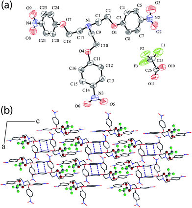 | ||
| Fig. 5 (a) ORTEP plot of complex 5; (b) Crystal packing diagram of complex 5 viewed down the b-axis showing the formation of bilayer assembly of cationic L moieties along c-axis with trifluoroacetate anions situated within the tripodal clefts between the adjacent cationic arrays. | ||
Silicon hexafluoride salt [2HL+]·[SiF62−]·2H2O (6) was obtained on reaction of the tripodal ligand L with HF, presumably as a result of corrosion with the glass surface (beaker). The overall molecular structure is a 2:1 ionic salt of L and H2SiF6 with disordered water molecules present in the crystal lattice as solvent of crystallization and crystallizes in triclinic space groupP with Z = 3. An ORTEP plot of 6 is shown in Fig. S1 (ESI)† along with the atom numbering scheme. The asymmetric unit contains three HL+ units and correspondingly 1.5 SiF62− units are present for charge neutralization. In an attempt to understand the binding of polyatomic anion (SiF62−) by the tripodal podand LH+, we have analyzed the interaction of SiF62− with the surrounding ligand moieties. Water molecules do not have any kind of non-covalent interactions either with the cationic tripodal units or the anionic counterpart in the solid-state.
The binding of SiF62− by multiple protonated L units clearly reveals that the hexafluorosilicate ions involving silicon atoms Si(1) and Si(2) interacts with four tripodal units each (Fig. 6a) but with seventeen-point and sixteen-point coordination respectively solely via (N–H)+⋯F and C–H⋯F interactions. The hydrogen atoms HN1 and HN9 of the protonated bridgehead nitrogen atoms from two receptor units on either side of Si(1)F62− are bifurcated (N–H)+⋯F hydrogen bonded to fluorine atoms F1, F2 and F4, F6, respectively, (N1⋯F1 = 3.118 Å, <N1–H⋯F1 = 135°; N1⋯F2 = 2.742 Å, < N1–H⋯ F2 = 159°; N9⋯F4 = 3.217 Å, <N9–H⋯F4 = 125°; N9⋯F6 = 2.693 Å, < N9–H⋯ F6 = 166°). In addition, all six F atoms of Si(1)F62− are involved in moderate C–H⋯F hydrogen bonding with different alkyl and aryl hydrogen of the encircling LH+ units. F1 is involved in C–H⋯F interaction with the methylene hydrogen H1A and H57B of two surrounding ligand moieties and F2 is hydrogen bonded to H25A. F3 is engaged in bifurcated acceptor hydrogen bonding with the methylene hydrogen H1B and aryl hydrogen H44 while F4 forms five C–H⋯F contacts with the surrounding receptor moieties involving aliphatic hydrogen H25A, H42A, H49B, H66B and aromatic proton H44. F5 is the only atom that is in a single point contact with the methylene hydrogen H49A and finally F6 is involved in C–H⋯F hydrogen bonding interaction with the methylene hydrogen H57B and H58B from two different cations completing the 17 hydrogen-bonding contacts on Si(1)F62−. Thus, both F1 and F6 forms trifurcated acceptor hydrogen bonds and H25A, H44 and H57B are all involved in bifurcated hydrogen bonding in the anion complex.
 | ||
| Fig. 6 (a) Coordination environment of the two symmetrically non-equivalent SiF6− anions in complex 6, three LH+ conformers have been shown in different colours; (b) Close-up view of hexafluorosilicate binding depicting the sixteen hydrogen-bonding interactions of Si(2)F6− anion (green dotted lines) with four cationic receptor units; (c) Packing diagram of complex 6 viewed down the a-axis showing the π⋯π stacking arrangement of the cationic L units almost diagonal to the bc-plane with the hexafluorosilicate anions situated between the adjacent cationic arrays. | ||
Hexafluorosilicate ion involving Si(2) is situated in a symmetrical environment with four encircling receptor units providing a sixteen point contacts to it. A close up view of the coordination of Si(2)F62− anion by four cationic L units is depicted in Fig. 6b. Hydrogen HN5 of the protonated nitrogen forms bifurcated hydrogen bond with F8 and F9 (N5⋯F8 = 2.756 Å, <N5–H⋯F8 = 168°; N5⋯F9 = 2.997 Å, < N5–H⋯ F9 = 127°). F7 and F8 are engaged in moderate C–H⋯F interaction with alkyl hydrogen H33B and H9A, respectively, whereas F9 is involved in a four point C–H⋯F interaction with H9A, H18A, H20 and H33A. The details of the C–H⋯F interaction are given in Table 1. An average hydrogen bond distance of 3.276 Å implies active participation of the alkyl C–H donors towards hexafluorosilicate binding via moderate C–H⋯F inteactions. The cationic tripodal units are cross linked among themselves via multiple interligand C–H⋯Onitro interaction and π⋯π stacking between the phenyl units (Fig. 6c) generating a 3D supramolecular hydrogen bonded network with solvent accessible voids measuring a total volume of 434 Å3 in the structure. The presence of only three difference Fourier peaks in such a large volume shows that most of the water molecules could not be located due to disorder.
Rationalization of structural features
The hydrogen of the protonated bridgehead nitrogen in L is exo-oriented in all six complexes and is involved in forming (N–H)+⋯anion (1, 2, and 4) or bifurcated (N–H)+⋯anion hydrogen bonds (3, 5 and 6) depending upon the dimensionality of the counter anion. Absence of intramolecular non-covalent interactions between the receptor arms is likely to be responsible for the flat and extended orientation of the tripodal arms in LH+ units of all complexes. The binding of different anions by multiple LH+ units reveal that nitrate, perchlorate and hexafluorosilicate anions are coordinated through four tripodal units each whereas coordination of halides and trifluoroacetate are provided by three and five LH+ units respectively. Hexafluorosilicate ion involving Si(1) is located in an unsymmetrical coordinating environment with a 17 point contacts whereas SiF62− involving Si(2) is situated in a symmetrical environment with a 16 point attachment provided by four LH+ units in each case (Fig. 6b). The cationic receptor molecules are self-assembled via multiple C–H⋯Onitro hydrogen bonds in all six ionic complexes and π⋯π stacking interactions in complexes 1, 2, 5 and 6 generating 3D supramolecular networks. Intermolecular C–H⋯π interaction has been observed only in complex 2. Thus, it can be rationalized that, on protonation of receptor L in presence of anions of varied dimensionality there is a remarkable change in the orientation of tripodal arms due to the torsional differences (Table S2, ESI)† and overall packing as well probably because of the variable coordination modes adopted by different anions through weak C–H⋯anion hydrogen bonds to provide a favourable electrostatic environment around themselves. Moreover, multiple interligand C–H⋯Onitro interactions provide further stabilization to the supramolecular complexes 1–6 (Table S1, ESI).†To investigate the solution-state binding of different anions with the cationic receptor molecule, we have protonated L with p-toluenesulfonic acid.24 The addition of tetrabutylammonium (TBA) salts of anions (Br−, NO3− and ClO4−) separately to [HL+]·[OTs] in DMSO-d6 showed a downfield chemical shift of the aromatic C–H resonances (Δδ = 0.02–0.03 ppm), which indicates participation of the receptor in anion bindingvia weak hydrogen-bonding interactions of C–H protons (see ESI).† However, marginal spectral changes have been observed for the aliphatic C–H resonances. Considerable downfield shift of the aliphatic CH2 protons (Δδ = 0.30–0.73 ppm) in the 1H-NMR spectra of anion complexes 1–6 indicate the influence of the protonation at the apical nitrogen on the neighbouring methylene protons (Fig. S11–S16, ESI).† Since most of the aliphatic CH⋯anion contacts are formed with the H atoms on carbons subsequent to the ammonium ion, it can be argued that these H atoms are simply in the way due to the close approach of anions to the positively charged N atom by forming electrostatic (N–H)+⋯anion interaction. The other possibility is that protonation at the apical nitrogen render the methylene CH2groups sufficiently acidic for their active participation towards anion bindingvia weak CH⋯anion interactions with an average C–H hydrogen bond distance of 3.436 Å. The feeble nature of C–H hydrogen bonds is also reflected from the marginal chemical shift of C–H proton resonances in 1H NMR spectra and an average aliphatic C–H⋯anion contact angle of 141° range from 109 to 162°. Though charge neutralisation in the crystals and conventional hydrogen bonds are the main driving forces in the formation of supramolecular complexes, yet the weak CH hydrogen bonds provide added stabilization to the complexes and thus, satisfies the geometrical necessity of the LH+ units by providing a favourable electrostatic environment around the anions. Thus, the importance and authenticity of these short CH⋯anion contacts can hardly be ignored.
Conclusions
In summary, we have shown the solid state evidence for the active participation of both aliphatic CH2 and aryl CH groups in binding of different anions with the protonated tripodal receptor L, exhibiting aliphatic C–H⋯anion hydrogen bond strengths comparable to those of aryl C–H⋯anion hydrogen bond. They are also actively involved in the self assembly of cationic tripodal moieties by forming C–H⋯Onitro hydrogen bonds with the oxygen atoms of terminal nitro groups. Structural studies of anion binding with protonated L revealed that none of the guests is encapsulated inside the tripodal arms irrespective of size, shape, and charge of the anions presumably because of the absence of conventional anion hydrogen bonding functionalities. However, detailed structural investigation clearly demonstrates that the self-alignment and orientation of the multiple ligand moieties, depending upon the dimensionality of the incoming anionic guest play a crucial role in making various molecular interactions possible in the binding of the various anions. Finally, cationic tripodal receptors bearing electron withdrawing substituents appear to be well-suited for fundamental studies of C–H⋯anion hydrogen bonding, with the present study clearly showing the importance of aliphatic as well as aromatic C–H bond donors in binding of anions when these donors are pre-organized involving multiple receptor units. Therefore, due to the interesting structural and binding properties, the tripodal podand receptor L can provide an excellent case of understanding C–H⋯anion hydrogen bonding in its protonated form. A systematic survey of complexation and selective recognition of anions in systems of this type, which involves crystal structure studies of several substituted tripodal receptor molecules in terms of careful modelling studies and charge density analyses are currently being pursued to get further insight into the nature of their binding modes.Acknowledgements
GD acknowledges DST (SR/S1/IC-01/2008) and CSIR (01-2235/08/EMR-II), New Delhi India for financial support and DST-FIST for single-crystal X-ray diffraction facility. SKD acknowledges IIT Guwahati, India for fellowship.Notes and references
- (a) A. Bianchi, K. Bowman-James and E. Garcia-Espana, Supramolecular Chemistry of Anions, Wiley-VCH, New York, 1997 Search PubMed; (b) B. H. M. Snellink-Ruel, M. M. G. Antonisse, J. F. J. Engbersen, P. Timmerman and D. N. Reinhoudt, Eur. J. Org. Chem., 2000, 165 CrossRef CAS.
- (a) M. D. Best, S. L. Tobey and E. V. Anslyn, Coord. Chem. Rev., 2003, 240, 3 CAS; (b) V. McKee, J. Nelson and R. M. Town, Chem. Soc. Rev., 2003, 32, 309 RSC; (c) J. L. Sessler, S. Camiolo and P. A. Gale, Coord. Chem. Rev., 2003, 240, 17 CAS; (d) C.-H. Lee, H.-K. Na, D.-W. Yoon, D.-H. Won, W.-S. Cho, V. M. Lynch, S. V. Shevchuk and J. L. Sessler, J. Am. Chem. Soc., 2003, 125, 7301 CrossRef CAS; (e) K. J. Wallace, W. J. Belcher, D. R. Turner, K. F. Syed and J. W. Steed, J. Am. Chem. Soc., 2003, 125, 9699 CrossRef CAS.
- (a) P. D. Beer and P. A. Gale, Angew. Chem., Int. Ed., 2001, 40, 486 CrossRef; (b) J. L. Sessler, P. A. Gale and W. S. Cho, Anion Receptor Chemistry, The Royal Society of Chemistry, Cambridge, UK, 2006 Search PubMed.
- (a) C. R. Bondy, P. A. Gale and S. J. Loeb, J. Am. Chem. Soc., 2004, 126, 5030 CrossRef CAS; (b) D. R. Turner, E. C. Spencer, J. A. K. Howard, D. A. Tocher and J. W. Steed, Chem. Commun., 2004, 1352 RSC; (c) S. O. Kang, M. A. Hossain, D. Powell and K. Bowman-James, Chem. Commun., 2005, 328 RSC.
- K. Bowman-James, Acc. Chem. Res., 2005, 38, 671 CrossRef CAS.
- (a) H.-J. Schneider and A. K. Yatsimirsky, Chem. Soc. Rev., 2008, 37, 263 RSC; (b) E. Garcia-Espana, P. Diaz, J. M. Llinares and A. Bianchi, Coord. Chem. Rev., 2006, 250, 2952 CrossRef CAS; (c) S. O. Kang, Md. A. Hossain and K. Bowman-James, Coord. Chem. Rev., 2006, 250, 3038 CrossRef CAS; (d) J. M. Llinares, D. Powell and K. Bowman-James, Coord. Chem. Rev., 2003, 240, 57 CAS.
- (a) P. S. Lakshminarayanan, I. Ravikumar, E. Suresh and P. Ghosh, Chem. Commun., 2007, 5214 RSC; (b) P. S. Lakshminarayanan, E. Suresh and P. Ghosh, Inorg. Chem., 2006, 45, 4372 CrossRef CAS.
- D. R. Turner, M. J. Paterson and J. W. Steed, J. Org. Chem., 2006, 71, 1598 CrossRef CAS.
- (a) S. Metzger and B. Lippert, J. Am. Chem. Soc., 1996, 118, 12467 CrossRef CAS; (b) P. Auffinger, S. Louise-May and E. Westof, J. Am. Chem. Soc., 1996, 118, 1181 CrossRef CAS; (c) G. R. Desiraju, Acc. Chem. Res., 1991, 24, 290 CrossRef CAS; (d) T. Steiner and W. Saenger, J. Am. Chem. Soc., 1992, 114, 10146 CrossRef CAS; (e) C. V. K. Sharma and G. R. Desiraju, J. Chem. Soc. Perkin Trans., 1994, 2345 Search PubMed; (f) T. Steiner, J. Chem. Soc., Perkin Trans., 1995, 1315 Search PubMed; (g) J. D. Chaney, C. R. Goss, K. Folting, B. D. Santarsiero and M. D. Hollingworth, J. Am. Chem. Soc., 1996, 118, 9432 CrossRef CAS.
- R. K. Castellano, Curr. Org. Chem., 2004, 8, 845 CrossRef CAS.
- (a) C. H. Lee, H.-K. Na, D.-W. Yoon, D.-H. Won, W.-S. Cho, V. M. Lynch, S. V. Schevchuk and J. L. Sessler, J. Am. Chem. Soc., 2003, 125, 7301 CrossRef CAS; (b) K. J. Wallace, W. J. Belcher, D. R. Turner, K. F. Syed and J. W. Steed, J. Am. Chem. Soc., 2003, 125, 9699 CrossRef CAS; (c) C. A. Ilioudis, D. A. Tocher and J. W. Steed, J. Am. Chem. Soc., 2004, 126, 12395 CrossRef CAS; (d) D. R. Turner, E. C. Spencer, J. A. K. Howard, D. A. Tocher and J. W. Steed, Chem. Commun., 2004, 1352 RSC; (e) M. J. Chmielewski, M. Charon and J. Jurczak, Org. Lett., 2004, 6, 3501 CrossRef CAS; (f) S. O. Kang, D. VanderVelde, D. Powell and K. Bowman-James, J. Am. Chem. Soc., 2004, 126, 12272 CrossRef CAS; (g) J. Y. Kwon, Y. J. Jang, S. K. Kim, K.-H. Lee, J. S. Kim and J. Yoon, J. Org. Chem., 2004, 69, 5155 CrossRef CAS.
- (a) J. Y. Kwon, Y. J. Jang, S. K. Kim, K.-H. Lee, J. S. Kim and J. Yoon, J. Org. Chem., 2004, 69, 5155 CrossRef CAS; (b) A. M. Costero, M. J. Banuls, M. J. Aurell, M. D. Ward and S. Argent, Tetrahedron, 2004, 60, 9471 CrossRef CAS; (c) S. Ghosh, A. R. Choudhury, T. N. G. Row and U. Maitra, Org. Lett., 2005, 7, 1441 CrossRef CAS.
- (a) K. Hiraoka, S. Mizuse and S. Yamabe, Chem. Phys. Lett., 1988, 147, 174 CrossRef CAS; (b) Z. M. Loh, R. L. Wilson, D. A. Wild and E. J. Bieske, J. Chem. Phys., 2003, 119, 9559 CrossRef CAS; (c) F. M. Raymo, M. D. Bartberger, K. N. Houk and J. F. Stoddart, J. Am. Chem. Soc., 2001, 123, 9264 CrossRef CAS.
- J. Yoon, S. K. Kim, N. J. Singh and K. S. Kim, Chem. Soc. Rev., 2006, 35, 355 RSC.
- (a) V. S. Bryantsev and B. P. Hay, Org. Lett., 2005, 7, 5031 CrossRef CAS; (b) O. B. Berryman, V. S. Bryantsev, D. P. Stay, D. W. Johnson and B. P. Hay, J. Am. Chem. Soc., 2007, 129, 48 CrossRef CAS.
- B. P. Hay and V. S. Bryantsev, Chem. Commun., 2008, 2417 RSC.
- V. S. Bryantsev and B. P. Hay, J. Am. Chem. Soc., 2005, 127, 8282 CrossRef CAS.
- P. Pramanik, M. Bhuyan, R. Choudhury and G. Das, J. Mol. Struct., 2008, 879, 88 CrossRef CAS.
- Saint, Smart and XPREP, Siemens Analytical X-ray Instruments Inc., Madison, Wisconsin, USA, 1995 Search PubMed.
- G. M. Sheldrick, SADABS: software for Empirical Absorption Correction, University of Gottingen, Institute fur Anorganische Chemieder Universitat, Tammanstrasse 4, D-3400 Gottingen, Germany, 1999–2003 Search PubMed.
- (a) G. M. Sheldrick, SHELXS-97, University of Gottingen, Germany, 1997 Search PubMed; (b) G. M. Sheldrick, SHELXL-97, Program for Crystal Structure Refinement; University of Gottingen, Germany, 1997 Search PubMed.
- (a) L. J. Farrugia, J. Appl. Crystallogr., 1997, 30, 565 CrossRef CAS; (b) Mercury 1.3 Supplied with Cambridge Structural Database, CCDC: Cambridge, U.K., 2003–2004 Search PubMed.
- (a) S. K. Dey and G. Das, Cryst. Growth Des., 2010, 10, 754 CrossRef CAS; (b) A. S. Singh and P. K. Bharadwaj, Dalton Trans., 2008, 738 RSC.
- P. S. Lakshminarayanan, I. Ravikumar, E. Suresh and Pradyut Ghosh, Inorg. Chem., 2007, 46, 4769 CrossRef CAS.
Footnotes |
| † Electronic supplementary information (ESI) available: X-Ray crystallographic file of the structures in CIF format; ORTEPs, selected non-covalent interactions, selected torsion values, crystal packing networks, 1H and 13C spectra. CCDC reference numbers 761161–761166. For ESI and crystallographic data in CIF or other electronic format see DOI: 10.1039/c0ce00316f |
| ‡ Crystal data for 1: FW = C24H25ClN4O9, M = 548.93, CCDC = 761161, T = 298(2) K, triclinic, space groupP, a = 7.475(6), b = 13.365(10), c = 13.784(10) Å, α = 98.90(3)°, β = 102.77(3)°, γ = 105.84(3)°, V = 1257.6(17) Å3, Z = 2, μ = 0.213 mm−1, 3172 unique reflections, 2570 observed (Rint = 0.1018), R(F) = 0.0518 (I > 2σ(I), wR(F2) = 0.1240 (all data). 2: FW = C24H25BrN4O9, M = 593.38, CCDC = 761162, T = 298(2) K, triclinic, space groupP, a = 7.6818(6), b = 13.3835(11), c = 13.8995(12) Å, α = 99.080(1)°, β = 103.12(5)°, γ = 106.33(3)°, V = 1297.45(48) Å3, Z = 2, μ = 1.644 mm−1, 6469 unique reflections, 6386 observed (Rint = 0.0188), R(F) = 0.0344 (I > 2σ(I), wR(F2) = 0.0928 (all data). 3: FW = C24H25N5O12, M = 575.49, CCDC = 761163, T = 298(2) K, monoclinic, space groupP21/n, a = 15.2305(7), b = 8.9608(4), c = 20.0560(10) Å, β = 101.073(3)°, V = 2686.2(2) Å3, Z = 4, μ = 0.116 mm−1, 6659 unique reflections, 6185 observed (Rint = 0.0733), R(F) = 0.0611 (I > 2σ(I), wR(F2) = 0.1162 (all data). 4: FW = C24H25ClN4O13, M = 612.93, CCDC = 761164, T = 298(2) K, monoclinic, space groupP21/c, a = 11.9923(5), b = 12.5750(6), c = 18.0740(8) Å, β = 103.045(2)°, V = 2655.3(2) Å3, Z = 4, μ = 0.221 mm−1, 6585 unique reflections, 5805 observed (Rint = 0.0784), R(F) = 0.0460 (I > 2σ(I), wR(F2) = 0.0969 (all data). 5: FW = C26H25N4O11F3, M = 626.50, CCDC = 761165, T = 298(2) K, triclinic, space groupP, a = 6.8340(9), b = 12.5542(11), c = 16.8656(18) Å, α = 99.533(5)°, β = 94.301(6)°, γ = 99.636(7)°, V = 1399.0(3) Å3, Z = 2, μ = 0.129 mm−1, 7010 unique reflections, 6711 observed (Rint = 0.101), R(F) = 0.0688 (I > 2σ(I), wR(F2) = 0.1081 (all data). 6: FW = C48H50F6N8O20Si, M = 1201.05, CCDC = 761166, T = 298(2) K, triclinic, space groupP, a = 15.4544(9), b = 17.9320(9), c = 18.6070(10) Å, α = 116.352(3)°, β = 94.269(5)°, γ = 106.342(3)°, V = 4313.2(4) Å3, Z = 3, μ = 0.141 mm−1, 24200 unique reflections, 19542 observed (Rint = 0.0316), R(F) = 0.0935 (I > 2σ(I), wR(F2) = 0.2440 (all data). |
| This journal is © The Royal Society of Chemistry 2011 |