DOI:
10.1039/C0CE00276C
(Paper)
CrystEngComm, 2011,
13, 287-292
Highly ordered Ge-incorporated akaganeite (β-FeOOH): a tunnel-type nanorod
Received
7th June 2010
, Accepted 17th June 2010
First published on 6th September 2010
Abstract
A highly ordered Ge-incorporated akaganeite with the atomic ratio of Ge/Fe = 0.14 and Cl/Fe = 0.11 was firstly synthesized through hydrolysis and acidification of a mixed solution of FeCl3·6H2O and TEOGe (Ge(OC2H5)4) under the α-Fe2O3 synthesis conditions. The newly synthesized Ge-akaganeite shows a monodisperse nanorod with 15–17 nm in width and ∼200 nm in length, the distinctly enhanced structural ordering and stability, and substantial differences in crystallographic and magnetic features. Here we propose a hypothetical akaganeite model with Ge occupying the tunnel sites as Ge(OH)40 based on crystallographic and chemical analyses.
Introduction
Akaganeite (β-FeOOH) is a polymorph of ferric oxyhydroxides (FeOOH) with 4 double chains of FeO3(OH)3 octahedra, which form a tunnel-type nanoporous structure of 0.5 nm × 0.5 nm in size running along [010].1,2 The tunnel sites are partly occupied by Cl− ions, and the negative charge is balanced by adding H+, which forms hydroxyl (OH−) groups with oxygen.1–3 The Cl− ions are believed to play an essential role in stabilizing the structure.4–6 Therefore the structural formula of akaganeite can be described as FeO1−x(OH)1+xClx. In nature it is found in the high chloride containing environments such as volcanic soils, brines, products of corrosion in marine environments and is also associated with meteorites.7 Recently, in spite of its unique sorption, ion exchange, and catalytic properties of the tunnel structure, akaganeite has been of great research interest as a means of preparing uniform nanocrystalline hematite particles (α-Fe2O3)8,9 rather than as a catalyst and absorbent in industrial applications. It is because akaganeite can be synthesized as rod-like structures and somatoids on the nanoscale,5 but its structural ordering and stability is low, and then it is easily transformed to the more stable form, α-Fe2O3 (hematite) by dehydration or dehydroxylation.9–12 Therefore if the structural ordering and stability of akaganeite are improved, akaganeite could be used as a unique catalyst for some specified nano-technical applications. Incorporation of ions into the structures of iron oxyhydroxides can modify their properties such as crystal size, morphology, structural ordering, and stability. Si-incorporated7 and anions-exchanged4,13–15 akaganeites are examples of incorporation studies investigated previously.
In the present study, we successfully synthesized a highly ordered Ge-incorporated akaganeite with the atomic ratio of Ge/Fe = 0.14 by a simple reproducible one-step hydrothermal method under the α-Fe2O3 (hematite) synthesis conditions. The newly synthesized Ge-akaganeite shows a monodisperse nanorod with 15–17 nm in width and ∼200 nm in length, and distinctly enhanced structural ordering and stability. Here we report a specified condition of Ge-incorporation into the akaganeite structure and its newly defined crystallographic, chemical, and magnetic characteristics.
Experimental
Synthesis of Ge-incorporated β-FeOOH
The experimental procedures for synthesizing the Ge-akaganeite nanorod are similar to those for synthesizing Ge-incorporated ferrihydrite suggested by Song et al.,16 except using ferric iron chloride hexahydrate (FeCl3·6H2O) instead of ferric iron nitrate nonahydrate (Fe(NO3)3·9H2O). The synthetic procedures are as follows.
(1) Tetra-ethyl-orthogermanate (TEOGe, Ge(OC2H5)4, 99.95 wt.%, Aldrich) was added dropwise to a stirred solution of 2 mM of FeCl3·6H2O until the molar ratio of Fe/Ge reached 2 and left to stand for 30 min under vigorous stirring.
(2) 1 M NaOH solution was added at the rate of 0.5 ml min−1 under vigorous stirring until the pH of solution reached 13 (Ge-Ak-1), 10 (Ge-Ak-2), and 5 (Ge-Ak-3), respectively, for checking pH- and Na-effects in Ge-incorporation. A batch with no addition of NaOH (pH ≈ 2) was also prepared (Ge-Ak-4).
(3) The pHs of 4 batches were brought down immediately to 1.5 by dropwise addition of 12 N HCl. In general, some Fe oxides (e.g.α-Fe2O3, hematite) are favorably precipitated under these pH conditions.17 The resulting solution gradually became light yellow in color and it was stirred for 1 h at room temperature. The suspension was then aged in the oven for 5 days at 95 °C.
(4) The final synthesized solution was flocculated by adding several drops of ammonia water and subsequently centrifuged. The supernatant was discarded and washed several times with deionized water and ethanol, and the flocculated sol was immediately dialyzed against deionized water for 3 days.
A drop of the dialyzed solution was deposited on a Former-backed copper grid for transmission electron microscopy (TEM). The rest of the solution was freeze-dried for characterization analyses. Pure akaganeite (Ak-ref) of rod-like form was also prepared by following the method of Schwertmann and Cornell.17
Chacterization
TEM images, high-resolution transmission electron microscopy (HRTEM) lattice fringe images and selected area electron diffraction (SAED) patterns were obtained with an omega-filter equipped JEOL JEM-2200FS transmission electron microscope operated at 200 kV. Conventional X-ray diffraction (XRD) analysis was performed on freeze-dried samples using a MXP 18A RINT-2500 X-ray diffractometer (MAC science, Japan) with Cu-Kα radiation. High-resolution synchrotron X-ray powder diffraction analysis for the Ge-incorporated akaganeite was performed at the 8C2 beamline of the Pohang Accelerator Laboratory (PAL), Korea. The diffraction pattern was collected using an X-ray beam with λ = 1.5489(1) Å in the range from 8 to 128.5°(2θ) at a step of 0.02° and a measurement time of 18 s per step. Profile-fitting of the data was performed using the GSAS suite of programs.18 The starting model of akaganeite was taken from the refinement result of Post et al.1 Thermogravimetric (TG) differential thermal analysis (DTA) data were collected in the range of 25–1000 °C with the rate increasing by 10 °C min−1 using TG-DTA 2000S (MAC science, Japan). Fourier-transform infrared (FT-IR) spectra were collected for the normal and heat-treated Ge-akaganeites using a Perkin-Elmer Paragon 1000 FT-IR spectrometer in the transmission mode on pellets containing 1 mg of sample in 170 mg of a KBr matrix. Samples were heated at the rate of 10 °C min−1 to target temperatures. Magnetization hysteresis loops, and zero-field-cooled (ZFC) and field-cooled (FC) magnetization data as a function of temperature were taken on a Quantum Design MPMS-5T SQUID magnetometer. ZFC magnetization curves were obtained by cooling in zero field from 300 K to 5 K and then by measuring the magnetization at stepwise increasing temperature 5 K to 300 K in a small applied field (100 Oe). The sample was cooled again in the same field, and FC magnetization curves were obtained by measuring stepwise from 5 K to 300 K. Hysteresis loops were obtained by using maximum applied fields up to 50 kOe at 5 K and 300 K.
Results and discussion
TEM images and diffraction results
The representative TEM micrographs of Ge-akaganeite (Ge-Ak-1) show monodisperse nanorods with 15–17 nm in width and ∼200 nm in length (Fig. 1a and b), and clearly visible lattice fringes (Fig. 1c). TEM-EDX analyses for the sample show that the atomic ratios of Ge/Fe are about 0.14. This indicates the successful incorporation of Ge into the structure. The atomic ratio of Cl/Fe of Ge-akaganeite is about 0.11, which is much lower than that of pure akaganeite (Ak-ref, Cl/Fe = 0.25). TEM images of samples synthesized under the conditions of Ge-Ak-2 and 3 are similar to those of Ge-Ak-1 (Fig. 2a–d), while those of Ge-Ak-4 (a batch of no-addition of NaOH) show the akaganeite nanorods with >200 nm in length (Fig. 2e and f). TEM images of the reference akaganeite (Ak-ref) also show monodisperse nanorods with ∼10 nm in width and ∼100 nm in length (Fig. 2g and h), but their shapes are not obvious compared with Ge-akaganeite nanorods. These results indicate that the specified pH conditions (pH = 13, 10, 5 and 2) adjusted by NaOH-addition may have a role to play in controlling the length of the akaganeite nanorods. TEM-EDX analyses for Ge-Ak-2 and 3 show that the atomic ratios of Ge/Fe are 0.14–0.18 and the ratios of Cl/Fe of Ge-akaganeite are 0.06–0.09 (Fig. 2). The selected area electron diffraction (SAED) pattern of the entire images for Ge-Ak-1 (Fig. 1d) shows tens of distinct diffraction features, of which d-spacings are matched well with those measured from the XRD pattern of Fig. 3. The measured d-spacings are consistent with those of pure akaganeite (PDF 42-1315), but most reflections have been shifted relative to the pure akaganeite (Fig. 1d and 3), and the peak intensities of the Ge-akaganeite are much more distinct and stronger than that of reference akaganeite (Fig. 3). These indicate that an increase of structural ordering and a little change in the unit cell occurred in the Ge-incorporated akaganeite. XRD patterns of samples Ge-Ak-2 and 3 are almost the same as that of Ge-Ak-1. The profile-fitting refinement result of high-resolution synchrotron X-ray powder diffraction data for the Ge-incorporated akaganeite (Ge-Ak-1) is shown in Fig. 4. The refinement was performed on the basis of the monoclinic (I2/m) cell dimensions (a = 10.5876(5), b = 3.03357(8), c = 10.5277(6) Å, β = 90.14(2)°, V = 338.13(2) Å3) proposed by Post et al.,1 and the final refined parameters are summarized in Table 1. Our results of profile-fitting refinement show the monoclinic (I2/m) cell dimensions with a = 10.5050(8), b = 3.0177(1), c = 10.4429(7) Å, β = 90.360(7)°, and V = 331.05(4)) Å3, which are distinctly shorter than those obtained by Post et al.1 (Table 1). The HRTEM image of Ge-Ak-1 shows a highly ordered akaganeite nanorod elongated to the b-axis in the ab-plane (Fig. 5a) and the arrangement of atoms in the structure, which are matched very well with the crystal model of akaganeite projected in the ab-plane (Fig. 5b). Unit cell parameters directly measured from the HRTEM image are a = 10.50 and b = 3.02 Å, being in good agreement with the SAED and XRD results. The XRD results and HRTEM images strongly indicate that a distinct increase of structural ordering and a substantial decrease in the unit cell parameters happened because of the Ge-incorporation into the akaganeite structure.
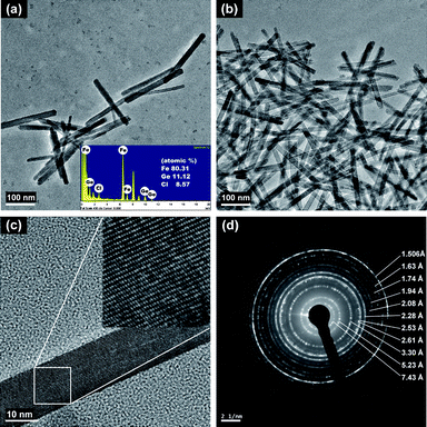 |
| | Fig. 1
TEM images of Ge-incorporated, monodisperse nanorods with 15–17 nm in width and ∼200 nm in length (a, b, c) and SAED patterns (d) synthesized under the conditions of Ge-Ak-1. | |
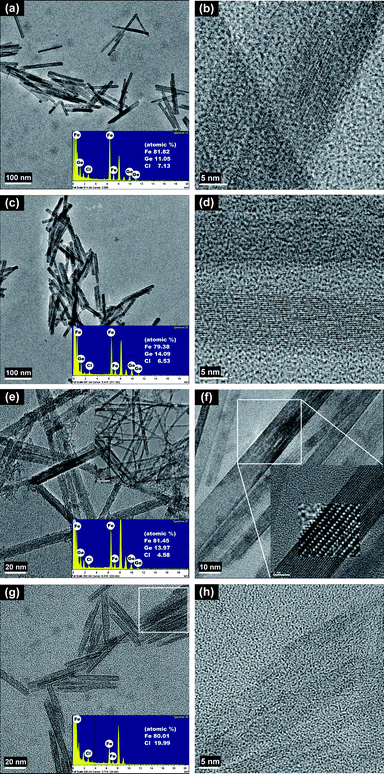 |
| | Fig. 2
TEM images of Ge-incorporated, monodisperse nanorods synthesized under the conditions of Ge-Ak-2 (a, b), Ge-Ak-3 (c, d), and Ge-Ak-4 (e, f), and of the reference akaganeite (Ak-ref) (g, h) prepared by following the method of Schwertmann and Cornell.17 | |
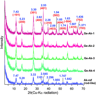 |
| | Fig. 3
X-Ray diffraction patterns (Cu-Kα) of Ge-akaganeite (Ge-Ak-1–4) and reference akaganeite (Ak-ref). | |
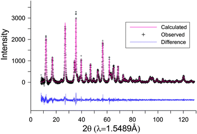 |
| | Fig. 4 Profile-fitting between the observed and calculated profiles of Ge-akaganeite (Ge-Ak-1). | |
Table 1 Profile-fitting refinement results for Ge-akaganeite (Ge-Ak-1) at room temperature
| Sample |
Space group |
a (Å) |
b (Å) |
c (Å) |
β (°) |
V (Å3) |
No. of data points |
w
Rp
|
Rp
|
|
Refinement cell parameters of pure akaganeite from Post et al.1X-Ray diffraction data collected at the beamline of NSLS and BNL were used.
|
| Ge-Akaganeite |
I2/m |
10.5050(8) |
3.0177(1) |
10.4429(7) |
90.360(7) |
331.05(4) |
5937 |
0.0531 |
0.0403 |
| Akaganeitea |
I2/m |
10.5876(5) |
3.03357(8) |
10.5277(6) |
90.14(2) |
338.13(2) |
2876 |
0.019 |
0.016 |
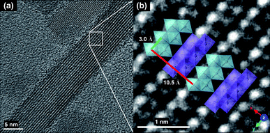 |
| | Fig. 5 An HR (high resolution) TEM image of Ge-Ak-1 shows a highly ordered akaganeite nanorod elongated to the b-axis (a), and the arrangement of the atoms in the structure matched well with the crystal model of akaganeite projected in the ab-plane (b). | |
Thermal properties
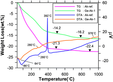
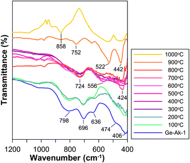
TG and DTA results for Ge-akaganeite synthesized under the conditions of Ge-Ak-1 and the reference akaganeite (Ak-ref) are given in Fig. 6. TG results of Ge-akaganeite show that the substantial weight loss occurs under 400 °C (∼14 wt.%), and over that the weight loss gradually slows and reaches 16.2 wt.% at 800 °C. This value is much lower than that of Ak-ref (22.4 wt.%). DTA results of Ge-Ak-1 show a distinct endothermic peak at 64 °C and two weak exothermic peaks at 280 °C and 945 °C, which would be related to the phase transformation. Whereas that of Ak-ref shows two endothermic peaks at 86 °C and 280 °C, and an exothermic peak at 392 °C, indicating the phase transformation to hematite (Fig. 6).5 Phase transformation of the Ge-akaganeite is confirmed by FT-IR analysis in Fig. 7. Ge-akaganeite shows distinct spectra at 406, 474, 636, 696, and 798 cm−1.5 After being heated to 300 °C, distinct spectra at 424, 556, and 724 cm−1 are observed, indicating the formation of ferrihydrite,5,16 probably Ge-ferrihydrite.16 It is well matched with a weak exothermic peak at 280 °C (Fig. 6). Transformation of the ferrihydrite to hematite occurs at about 900 °C, which is confirmed by two distinct spectra of hematite at 442 and 522 cm−1 in the 900 °C heated sample.5 It indicates strongly that Ge-incorporation should play a crucial role in stabilizing the akaganeite structure. The band at 858 cm−1 and a weak shoulder at about 950 cm−1 for the 1000 °C heated sample may be assigned to the Ge-O stretching,19 which would be due to the appearance of Ge-oxide (Fig. 7). The weak exothermic peak at 945 °C (Fig. 6) would be related to this phase change.
 |
| | Fig. 6
TG and DTA results for Ge-akaganeite synthesized under the conditions of Ge-Ak-1 and the reference akaganeite (Ak-ref), showing percent weight loss and μV as a function of temperature. | |
 |
| | Fig. 7
FT-IR spectra of Ge-akaganeite (Ak-Ge-1) and its heat-treated samples. | |
Magnetic properties
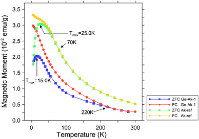
A comparison of zero-field-cooled (ZFC) and field-cooled (FC) susceptibility curves from Ge-akaganeite (Ge-Ak-1) and pure akaganeite (Ak-ref) is presented in Fig. 8, indicating that both samples show superparamagnetic behavior.20 As the samples are cooled in zero applied field (ZFC), the magnetic spins are frozen randomly. With increasing temperature and in the presence of an applied field, the spins begin to align, leading to an increase in the total magnetization to a maximum at the blocking temperature (TB), where the thermal fluctuations randomize the spins, and a superparamagnetic behavior results. As the samples are cooled in the applied field (FC), the spins are locked in a parallel alignment, then the magnetization remains relatively unchanged below TB.20,21 With increasing temperature, ZFC and FC curves merge. The presence of a maximum (Tmax) in the ZFC susceptibility curve, which is related to the blocking temperature (TB), is associated with the transition between magnetically relaxing superparamagnetic (unblocked) and thermally stable magnetization (blocked), that is, the magnetic domain structure.20,21 The ZFC curve of Ge-akaganeite (Ge-Ak-1) is characterized by the lower magnetic moment and Tmax (15.5 K) than those of reference akaganeite (Ak-ref) (25.0 K) (Fig. 8). The relatively low TB of Ge-Ak-1 would be attributed to the reduction in the average domain size by Ge-incorporation into the akaganeite structure.22 The convergence temperature of ZFC and FC curves can be assigned to TB of the largest domain in the sample.22,23 The ZFC and FC curves of Ge-Ak-1 are observed to converge abnormally at 220 K, which is much higher than that of Ak-ref (70 K). It is probably due to the differences in domain size, but the reason still remains questionable and additional research is needed to reveal the mechanism. Magnetic field vs. magnetic moment diagrams of Ge-Ak-1 and Ak-ref are presented in Fig. 9. The hysteresis loops are observed at 5 K for both samples, but they display a lack of saturation even at a magnetic field of 50 kOe. The magnetic moment of Ge-Ak-1 is a little lower than that of Ak-ref, indicating possible structural effects due to the Ge-incorporation into the akaganeite structure.
 |
| | Fig. 8 Zero-field-cooled (ZFC) and field-cooled (FC) measurements as a function of temperature for Ge-akaganeite (Ge-Ak-1) and pure akaganeite (Ak-ref). | |
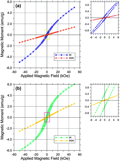 |
| | Fig. 9 Hysteresis loops for Ge-Ak-1 (a) and Ak-ref (b). Data were collected at 5 K and 300 K. Hysteresis loops did not reach saturation at 50 kOe. | |
Proposed model for Ge-incorporation
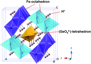
The above characterization results indicate that a highly ordered Ge-incorporated akaganeite was successfully synthesized. There are two possible sites for Ge in the akaganeite structure; either (1) Ge replaces a proportion of Fe3+ on the octahedral sites, or (2) Ge fits into the tunnels. Ge4+ (0.53 Å) is smaller than Fe3+ (0.64 Å) and is more highly charged, which means that Ge strongly favors tetrahedral coordination. Therefore the isomorphous replacement of Fe3+ by Ge4+ on the octahedral sites is unusual. On the other hand, if Ge fits into the tunnels of akaganeite, it might be expected to enter as a 4-coordination form of Ge(OH)40, or GeO44−, replacing Cl−. These two possible models can be expressed as follow; (1) (Fe1−yGey)O1−x(OH)1+xClx+y, and (2) FeO1−x(OH)1+xClx(Ge(OH)4)y, or FeO1−x(OH)1+xClx−4y(GeO4)y. Using the measured atomic ratio of Cl/Fe = 0.11 and Ge/Fe = 0.14 for Ge-akaganeite (Ge-Ak-1), x and y values can be determined. The calculated chemical compositions (wt.%) of model (1) and (2) are listed in Table 2. Theoretical weight losses (wt.% of Cl− + H2O) of model (1) and (2) are 12.87 and 16.67 wt.%, respectively, which are much lower than that of Ak-ref (20.13 wt.%) (Table 2). Total weight loss of Ge-akaganeite directly measured by TG analysis is 16.2 wt.% (Fig. 6), being well matched with the calculated weight loss of model (2). In addition, the considerable decrease of Cl− content (Cl/Fe = 0.10) conflicts with the possibility of Ge-incorporation into octahedral sites (model (1)). That is, on the basis of the model (1), the Cl− or OH− content should be increased to balance the increased positive charge by Ge4+ substitution for Fe3+. Although further investigations are required to confirm the model (2), the hypothesis of Ge-fitting into tunnel sites as Ge(OH)40 appears feasible because it would satisfy the coordination requirements of Ge4+, and is also compatible with the decrease of Cl− and the increase of ordering in the structure by Ge-incorporation. In particular, the increased thermal stability of Ge-akaganeite, which is confirmed by TG-DTA and FT-IR results (Fig. 6 and 7), can also be explained by the enhanced structural ordering through Ge-incorporation. Previous research has already shown the ion-exchange phenomena by some molecules such as bromide and molybdate in the tunnel sites of akaganeite, and their roles in stabilizing the structure.4,13–15 On the basis of the model (2), we simulated the hypothetical structure model of Ge-akaganeite as shown in Fig. 10. The tunnel sites are occupied by GeO44− tetrahedra with Ge–O length of ∼1.76 Å and its negative charge is balanced by adding H+, which forms hydroxyl (OH−) groups with oxygen (Fig. 10). We are going to perform the accurate structural refinement of the high-resolution synchrotron X-ray powder diffraction data for the Ge-akaganeite based on this proposed model using the Rietveld method. Therefore we expect to publish reasonable results from the refinement, including Ge-coordination and the exact position in the akaganeite structure.
Table 2 Relative weight proportions (wt.%) of elements, calculated on the basis of two possible structural models mentioned in the text
| Model |
x
a
|
y
a
|
Fe2O3 |
GeO2 |
Cl
− |
H2O
b |
Sum |
|
x and y values were determined using the measured atomic ratio of Cl/Fe = 0.11 and Ge/Fe = 0.14 for Ge-akaganeite (Ge-Ak-1), and Cl/Fe = 0.25 for reference akaganeite (Ak-ref).
Calculated from hydroxyl ion (OH−) content in the structure, assuming no additional H2O molecules. In the model (2), Ge was treated as Ge(OH)4° (a) and GeO44− (b).
|
| (1) (Fe1−yGey)O1−x(OH)1+xClx+y |
−0.032 |
0.120 |
73.92 |
13.21 |
3.61 |
9.26 |
100.0 |
| (2a) FeO1−x(OH)1+xClx(Ge(OH)4)y |
0.100 |
0.137 |
70.65 |
12.68 |
3.45 |
13.22 |
100.0 |
| (2b) FeO1−x(OH)1+xClx−4y(GeO4)y |
0.648 |
0.137 |
|
|
|
|
|
| Ak-ref FeO1−x(OH)1+xClx |
0.250 |
0.000 |
79.87 |
0.00 |
8.87 |
11.26 |
100.0 |
 |
| | Fig. 10 Polyhedral representation of a hypothetical Ge-akaganeite model simulated on the basis of the structural model with Ge occupying the tunnel sites as Ge(OH)40, viewing approximately down the b-axis. The GeO44− tetrahedra bound to H+ to form OH−groups for charge-balancing. | |
Conclusions
In conclusion, we have shown for the first time that Ge-incorporation into the akaganeite structure was confirmed by mineralogical and chemical methods, and that it can stabilize the akaganeite structure to the highly ordered, monodisperse nanorod form. The crystallographic and chemical analyses, and the structural formula calculation results lead us to suggest a hypothetical model with Ge occupying the tunnel sites as Ge(OH)40. For the exact structural refinement of Ge-akaganeite further investigations are required. However our ongoing research may provide a better understanding of the nature of the akaganeite structure, and offer the possibility of finding new phases incorporated by various ions with the potential to display specific properties and applications.
Acknowledgements
This work was supported (in part) by the Yonsei University Research Fund of 2009-7-0510.
Notes and references
- J. E. Post, P. J. Heaney, R. B. Von Dreele and J. C. Hanson, Am. Mineral., 2003, 88, 782 CAS.
- J. E. Post and V. F. Buchwald, Am. Mineral., 1991, 76, 272 CAS.
- K. Stahl, K. Nielsen, J. Jiang, B. Lebech, J. C. Hansen, P. Norby and J. Van Lanschot, Corros. Sci., 2003, 45, 2563 CrossRef CAS.
- J. Cai, J. Liu, Z. Gao, A. Navrotsky and S. L. Suib, Chem. Mater., 2001, 13, 4595 CrossRef CAS.
-
R. M. Cornell and U. Schwertmann, The Iron Oxides: Structure, Properties, Reactions, Occurrence and Uses, 2003, 2nd edn, Wiley-VCH, Weinheim, Germany Search PubMed.
- E. A. Deliyanni, D. N. Bakoyannakis, A. I. Zouboulis, K. A. Matis and L. Nalbandian, Microporous Mesoporous Mater., 2001, 42, 49 CrossRef CAS.
- R. M. Cornell, Z. Pflanzenernaehr. Bodenkd., 1992, 155, 449 Search PubMed.
- Y. Piao, J. Kim, H. B. Na, D. Kim, J. S. Baek, M. K. Ko, J. H. Lee, M. Shokouhimehr and T. Hyeon, Nat. Mater., 2008, 7, 242 CrossRef CAS.
- N. K. Chaudhari and J.-S. Yu, J. Phys. Chem. C, 2008, 112, 19957 CrossRef CAS.
- D. Wang, C. Song, Y. Zhao and M. Yang, J. Phys. Chem. C, 2008, 112, 12710 CrossRef CAS.
- J. P. Jolivet, C. Chaneac and C. Fiaud, Chem. Commun., 2004, 481 RSC.
- X. Wang, X. Chen, L. Gao, H. Zheng, M. Ji, C. Tang, T. Shen and Z. Zhang, J. Mater. Chem., 2004, 14, 905 RSC.
- W. R. Richmond, J. G. Hockridge, M. Loan and G. M. Parkinson, Chem. Mater., 2004, 16, 3203 CrossRef CAS.
- D. Carroll and W. R. Richmond, Am. Mineral., 2008, 93, 1641 CrossRef CAS.
- R. Chitrakar, S. Tezuka, A. Sonoda, K. Sakane and T. Hirotsu, Ind. Eng. Chem. Res., 2009, 48, 2107 CrossRef CAS.
- Y. Song, B. H. Bac, Y.-B. Lee, M. H. Kim, W.-S. Yoon, J. H. Kim and H.-S. Moon, CrystEngComm, 2010, 12, 1997 RSC.
-
U. Schwertmann and R. M. Cornell, Iron Oxides in the Laboratory: Preparation and Characterization, 2000, Wiley-VCH, Weinheim, Germany Search PubMed.
- B. H. Toby, J. Appl. Crystallogr., 2001, 34, 210 CrossRef CAS.
- B. H. Bac, Y. Song, M. H. Kim, Y.-B. Lee and I. M. Kang, Chem. Commun., 2009, 5740 RSC.
- J. L. Dormann, D. Fiorani and E. Tronc, Adv. Chem. Phys., 1997, 98, 283 CAS.
- T. S. Berquo, S. K. Banerjee, R. G. Ford and R. L. Penn, J. Geophys. Res., 2007, 112, B02102 CrossRef.
- M.-E. Y. Mohie-Eldin, R. B. Frankel and L. Gunther, J. Magn. Magn. Mater., 1994, 135, 65 CrossRef CAS.
- S. H. Tolbert, P. Sieger, G. D. Stucky, S. M. J. Aubin, C.-C. Wu and D. N. Hendrickson, J. Am. Chem. Soc., 1997, 119, 8652 CrossRef CAS.
|
| This journal is © The Royal Society of Chemistry 2011 |
Click here to see how this site uses Cookies. View our privacy policy here.