Guest induced transformations of assembled pyridyl bis-urea macrocycles†‡
Kinkini
Roy
a,
Chun
Wang
a,
Mark D.
Smith
a,
Mahender B.
Dewal
a,
Arief C.
Wibowo
a,
Julius C.
Brown
a,
Shuguo
Ma
b and
Linda S.
Shimizu
*a
aDepartment of Chemistry and Biochemistry, University of South Carolina, Columbia, South Carolina, USA. E-mail: shimizul@chem.sc.edu; Fax: +1 803-777-9521; Tel: +1 803-777-2066
bCollege of Engineering and Computing, University of South Carolina, Columbia, South Carolina, USA
First published on 10th August 2010
Abstract
Pyridine macrocycles with no cavities assembled into close packed columns yet absorbed guests including hydrogen, carbon dioxide, and iodine.
Many different approaches have been used to design materials with open channels that display permanent porosity.1 Recent examples indicate that a permanent pore or channel is not necessarily a requirement for the absorption of gases.2 Dynamic structural changes in coordination polymers induced new channels into which guest molecules were incorporated.3 Atwood et al. recently demonstrated that non-porous organic solids could expand by gas induced transformations.4 In this manuscript, we report a pyridyl bis-urea host (1, Fig. 1) that assembled into columns with high fidelity. Close packing of these columns gives a high density structure with no obvious channels. Co-crystallization of host 1 with trifluoroethanol (TFE) formed a crystalline inclusion complex host 1·TFE with TFE separating the columns of assembled bis-ureas. Heating induced desorption of the TFE regenerated the initial host 1 extended structure. While there are examples of crystals that can expand to absorb guests, we were surprised to observe type I gas adsorption isotherms with H2 and CO2, which usually indicate permanent channels. Furthermore, these crystals displayed reversible absorption of iodine to afford a stable crystalline host 1·I2 complex. Closer analysis suggested guest induced transformations that converted a higher density ‘guest free’ form of bis-urea host 1 to a lower density form. We investigated these structures by X-ray diffraction, X-ray photoelectron spectroscopy (XPS) and UV-vis spectroscopy. These studies suggest that the organic solid state can be dynamic and can expand to encapsulate guests.
 | ||
| Fig. 1 Macrocyclic bis-ureas 1 and 2: (a) structure of host 1 with intramolecular distances from C1 to C1* = 4.645 Å and N3 to N3* = 5.066 Å; (b) view along a single column of host 1 illustrating the hydrogen bonding pattern; (c) view depicting the packing of the columns. | ||
We have previously shown that ureas, preorganized within rigid frameworks, guided columnar assembly through the strong 3-centered urea hydrogen bonding motif.5Macrocycles with sizeable cavities afford open columnar channels that are accessible to gases and guests; however, we expected macrocycles that lacked a cavity to be nonporous. For example, previously reported m-xylene 2 assembled into columns through typical 3-centered urea interactions,6 but the inward facing aryl hydrogens were nearly within van der Waals contact. We recently synthesized pyridine 1, which contains basic interior nitrogens with no central cavity. Macrocycle 1 was synthesized in two steps from 2,6-dibromomethylpyridine and triazinanone (ESI†). Colorless crystals of 1 were obtained by vapor diffusion of methanol into a DMSO solution of 1 (10 mg/2 mL). X-Ray analysis§ revealed the expected bis-urea macrocycle (Fig. 1a). Accounting for van der Waals radii, the interior of the macrocycle was ∼1.1 × 1.8 Å (Fig. 1a). In comparison, gases used to measure porosity have kinetic diameters of 2.9 (H2) to 3.6 Å (N2).7 The individual macrocycles 1 were connected into columns by hydrogen bonds between the urea NH's and two different acceptors: the urea carbonyl oxygen and the pyridine nitrogen (Fig. 1b). The carbonyl oxygen formed slightly shorter interactions with an N–O distance of 2.904(2) Å vs. the pyridine N, which displayed an N–N distance of 3.082(2) Å. This hydrogen bonding motif gave a repeat distance of ∼4.7 Å, similar to the typical 3-centered urea motif.6 The chains of hydrogen bonds run along the crystallographic b axis and the columns are densely packed with no obvious channels (Fig. 1c).
Host 1 also crystallized through the vapor diffusion of TFE into a DMSO solution of 1 (10 mg/2 mL) to afford a 1·TFE complex. This structure showed columns with similar distances from the urea NHs to the heteroatoms (N–O = 2.928(4) Å, N–N = 3.038(4) Å). The important difference between the two structures was the hydrogen bonding interaction between the alcohol of TFE and urea carbonyl oxygen (Fig. 2a). The TFE forms an interstitial layer between a layer of columns (Fig. 2b). There is a change in symmetry between the solvent free and solvent complex crystals from monoclinic z = 2 to triclinic z = 1. To compare their volumes, we divided the solvent free cell volume by 2. The host 1·TFE had a larger volume (563.69 Å3) vs.host 1 (364.39 Å3), which reflected the space occupied by solvent.
 | ||
| Fig. 2 Views from the X-ray structure of host 1·TFE: (a) the hydrogen bonding environment of a single macrocycle was nearly identical to the solvent-free structure except for a TFE molecule that was hydrogen bonded to the carbonyl; (b) view depicting the packing of the columns. | ||
These crystalline solids were ground to powders and examined by powder X-ray diffraction. In each case, the observed PXRD patterns closely matched the theoretical PXRD pattern calculated from the respective single crystal structures, indicating that these bulk powders had the same overall structure as their crystalline solids (ESI†). The solvent was removed from host 1·TFE powder by heating and the powder re-examined by PXRD (Fig. 3a). The peak positions and intensities were similar to the original host 1 structure.
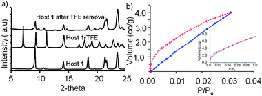 | ||
| Fig. 3 (a) Comparison of PXRD patterns for host 1 (bottom), host 1·TFE (middle) and host 1·TFE after TFE removal (top); (b) carbon dioxide adsorption isotherms at 273 K for host 1 (adsorption in blue, desorption in red) and hydrogen adsorption isotherms at 273 K for host 1 (inset). | ||
Host 1 and 2 were not expected to display permanent porosity and were examined as controls for gas adsorption. Surprisingly, host 1 crystals displayed a type I gas adsorption isotherm with CO2 (g) at 273 K consistent with microporous materials (Fig. 3b)8 as did host 2 (ESI†). The Brunauer–Emmett–Teller method was applied to the CO2 isotherm for host 1 at P/P0 between 0.016 and 0.028. The calculated surface area of 190 M2 g−1 corresponds to a total pore volume of 3.852 × 10⁻³ cm3 g−1 for pores smaller than 6.3 Å in diameter. Host 1 also displayed a similar type 1 adsorption isotherm with H2 (g) (Fig. 3b, inset). Both these gases have kinetic diameters that were larger than any void in the hosts. Thus, our hypothesis is that these hosts undergo gas induced transformations where the columns are pushed apart to accept the gas as observed in the host 1·TFE inclusion complex.
The ability of host 1 to form inclusion complexes with TFE through hydrogen bonding interactions with the unsatisfied oxygen lone pair, led us to the consider other guests whose structures would be easier to monitor. In host 2, the lone pairs were occupied in the 3-centered urea hydrogen bonds, thus this compound was tested as a control. We next investigated if hosts 1 and 2 absorbed I2, which was well-known to form charge transfer complexes with pyridine.9 The colorless crystals of hosts 1 and 2 were exposed to iodine vapors in a sealed container for 1–9 days. The vapor loading of iodine in host 1 to afford red crystals was kinetically slow, requiring ∼7 days to reach equilibrium. The desorption of iodine from these crystals was followed by thermogravimetric analysis (TGA). A one step desorption with 19.18% weight loss was observed between 60 °C to 140 °C from the host 1·I2 complex (Fig. 4a). Assuming that this weight loss corresponded to I2, we calculated a 3![[thin space (1/6-em)]](https://www.rsc.org/images/entities/char_2009.gif) ∶1 host∶guest ratio in the host 1·I2 complex. No weight loss was observed for the iodine treated host 2 samples, indicating that I2 was not absorbed.
∶1 host∶guest ratio in the host 1·I2 complex. No weight loss was observed for the iodine treated host 2 samples, indicating that I2 was not absorbed.
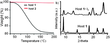 | ||
| Fig. 4 (a) TGA desorption curves for the iodine treated host 1 and host 2; (b) comparison of the PXRD patterns of host 1 and host 1·I2. | ||
Iodine could also be loaded reproducibly from an ethanolic solution and reached a saturation absorption of 280 (±20) mg I2 per gram of 1. This corresponds to the same 3∶1 binding ratio (1∶I2). To further investigate this binding phenomenon, host 1 (55 mg) was loaded in a capillary and equilibrated with iodine vapor for 7 days. We monitored the daily increase in volume by measuring the change in length. After 7 days a 14% increase in volume was observed (ESI†). The expansion of 1 was presumably due to the formation of a clathrate (host 1·I2).
Powder X-ray diffraction (PXRD) was used to compare the structure of the host 1 and its I2 complex. The host 1·I2 complex exhibited a PXRD pattern (Fig. 4b top) that was different from the free host. We observed a shift in the diffraction peak positions towards smaller 2θ values for the lower angle (102) peak from 14.1° to 12.55° and the (202) peak (21.3° to 19.6°). These changes suggested that the cell was expanding in the a–c direction as expected for iodine bound between the columns. The iodine was removed by heating and the PXRD positions and intensities mirrored those of the initial host 1 structure (ESI†).
We next investigated the nature of the bound iodine species. The empty host 1 exhibited an absorbance maximum at λmax 278 nm that was blue shifted to 262 nm in the 1·I2 complex, indicative of a charge transfer (CT) complex.9,10 Two additional absorbance bands were observed at λmax 286 and 355 nm, which were characteristic of iodine charge transfer bands (ESI†).11
Solid-state IR was used to compare host 1, 2, and the host 1·I2 complex. Host 2 has typical urea hydrogen bonds with two NH stretches at 3365 and 3306 cm−1. In the host 1 structure, the NH's were paired with two separate acceptors, which was reflected in the IR by the shift of the NH stretch to shorter wavenumbers (3328 and 3269 cm−1).12 Little change was observed in the NH region upon uptake of iodine. Only one NH stretch shifted from 3326 to 3321 cm−1. This may signal a slight strengthening of the pyridine NH hydrogen bond. No change was observed in the carbonyl band (1658 cm−1). We observed small perturbations in the pyridine ring in the 1·I2 complex. The C![[double bond, length as m-dash]](https://www.rsc.org/images/entities/char_e001.gif) N stretch moved to higher frequency (from 1568 to 1572 cm−1) and the in plane pyridine H-deformation shifted from 1106 cm−1 to 1130 cm−1.13
N stretch moved to higher frequency (from 1568 to 1572 cm−1) and the in plane pyridine H-deformation shifted from 1106 cm−1 to 1130 cm−1.13
The electronic structure of empty host 1 (Fig. 5a) and the host 1·I2 complex (Fig. 5b) was further probed by XPS.14 Two intense peaks shown in Fig. 5b around 620 eV were I 3d core level XPS lines. No other iodine peaks were observed in this region suggesting that only one type of iodine was present.15 The I MNN Auger line and I3d XPS spectrum for NaI reference were measured and the Auger parameter obtained.16 The 1·I2 sample showed a similar Auger parameter, which suggested that iodine acquired a partial negative charge upon complex formation.17 The XPS spectrum of N1s for host 1·I2 showed that the binding energy of N1s was higher than that for host 1, suggesting that the pyridine nitrogen was partially positive in host 1·I2 (ESI†).17 Taken together, these experiments support the formation of a pyridine–iodine CT complex that does not significantly alter the hydrogen bonding motif of the individual columns.
 | ||
| Fig. 5 Comparison of XPS survey scans: (a) host 1; (b) host 1·I2 complex. | ||
In summary, we report a pyridine functionalized bis-urea macrocycles that self-assembled into columnar structures lacking pores. Despite the lack of pores, this host was able to complex guests including TFE and I2 that can interact relatively strongly with the host. More surprising was the ability of this close packed organic host to absorb weakly interacting guests including H2 (g) and CO2 (g). These results highlight the potential use of organic crystals as sorbants. We are now investigating the binding of other guests within this new host as well as within larger pyridyl bis-urea macrocycles.
The authors acknowledge support for this work from the NSF (CHE-0718171, CHE-1012298) and from the University of South Carolina, Office of Research and Health Sciences.
Notes and references
- M. E. Davis, Nature, 2002, 417, 813 CrossRef CAS; O. M. Yaghi, M. O'Keeffe, N. W. Ockwig, H. K. Chae, M. Eddaoudi and J. Kim, Nature, 2003, 423, 705 CrossRef CAS.
- S. J. Dalgarno, P. K. Thallapally, L. J. Barbour and J. L. Atwood, Chem. Soc. Rev., 2007, 36, 236 RSC.
- C.-L. Chen, A. M. Goforth, M. D. Smith, C.-Y. Su and H.-C. zur Loye, Angew Chem., Int. Ed., 2005, 44, 2; R. Kitaura, K. Seki, G. Akiyama and S. Kitagawa, Angew. Chem., Int. Ed., 2003, 42, 428 CrossRef CAS; K. Biradha, Y. Hongo and M. Fujita, Angew. Chem., Int. Ed., 2002, 41, 3395 CrossRef CAS; S. A. Dalrymple and G. K. H. Shimizu, Chem. Commun., 2006, 956 RSC; A. Kondo, H. Noguchi, S. Ohnishi, H. Kajiro, A. Tohdoh, Y. Hattori, W.-C. Xu, H. Tanaka, H. Kanoh and K. Kaneko, Nano Lett., 2006, 6, 2581 CrossRef CAS; C.-L. Chen and A. M. Beatty, J. Am. Chem. Soc., 2008, 130, 17222 CrossRef CAS.
- J. L. Atwood, L. J. Barbour, A. Jerga and B. L. Schottel, Science, 2002, 298, 1000 CrossRef CAS; P. K. Thallapally, L. Dobrzanska, T. R. Gingrich, T. B. Wirsig, L. J. Barbour and J. L. Atwood, Angew. Chem., Int. Ed., 2006, 45, 6506 CrossRef; P. K. Thallapally, B. P. McGrail, S. J. Dalgarno, H. R. Schaef, J. Tian and J. L. Atwood, Nat. Mater., 2008, 7, 146 CrossRef CAS.
- M. B. Dewal, Y. Xu, J. Yang, F. Mohammed, M. D. Smith and L. S. Shimizu, Chem. Commun., 2008, 3909 RSC; L. S. Shimizu, A. D. Hughes, M. D. Smith, M. J. Davis, P. Zhang, H.-C. zur Loye and K. D. Shimizu, J. Am. Chem. Soc., 2003, 125, 14972 CrossRef CAS.
- L. S. Shimizu, M. D. Smith, A. D. Hughes and K. D. Shimizu, Chem. Commun., 2001, 1592 RSC.
- D. W. Breck, Zeolite Molecular Sieves: Structure, Chemistry, and Use, 1974, p. 752 Search PubMed.
- K. S. W. Sing, D. H. Everett, R. A. W. Haul, L. Moscou, R. A. Pierotti, J. Rouquerol and T. Siemieniewska, Pure Appl. Chem., 1985, 57, 603 CrossRef CAS.
- C. Reid and R. S. Mulliken, J. Am. Chem. Soc., 1954, 76, 3869 CrossRef CAS; N. Rao, S. Rao, G. Babu and D. Ziessow, Spectrochim. Acta, Part A, 1990, 46, 1107 CrossRef.
- C. Hayakawa, K. Urita, T. Ohba, H. Kanoh and K. Kaneko, Langmuir, 2009, 25, 1795 CrossRef CAS; C. Reid and R. S. Mulliken, J. Am. Chem. Soc., 1954, 76, 3869 CrossRef CAS.
- De Laurentis, V. Losacco, M. A. Milillo and A. Zarrilli, Boll. Chim. Farm., 2001, 140, 15 Search PubMed.
- R. M. Silverstein, F. X. Webster and D. J. Kiemle, in Spectroscopic Identification of Organic Compounds, John Wiley & Sons, Inc, Hoboken, NJ, 7th edn., 2005, pp. 72–126, ch. 2 Search PubMed.
- F. M. Abdel Kerim and F. A. Fotouh, Appl. Spectrosc., 1976, 30, 200 CrossRef CAS.
- C. M. Whelan, F. Cecchet, R. Baxter, F. Zerbetto, G. J. Clarkson, D. A. Leigh and P. Rudolf, J. Phys. Chem. B, 2002, 106, 8746.
- L. Grigorian, K. A. Williams, S. Fang, G. U. Sumanasekera, A. L. Loper, E. C. Dickey, S. J. Pennycook and P. C. Eklund, Phys. Rev. Lett., 1998, 80, 5560 CrossRef CAS; Z. He, X. Xu, S. Song, L. Xie, J. Tu, J. Chen and B. Yan, J. Phys. Chem. C, 2008, 112, 16431 CrossRef CAS.
- K. R. Kissell, K. B. Hartman, P. A. W. Van der Heide and L. J. Wilson, J. Phys. Chem. B, 2006, 110, 17425 CrossRef CAS.
- W. Wu, L. Liu, Y. Li, Z. Guo, L. Dai and D. Zhu, Fullerenes Nanotubes Carbon Nanostruct., 2003, 11, 89 Search PubMed; S. Ye, A. K. Vijh and L. H. Dao, J. Electrochem. Soc., 1997, 144, 90 CrossRef CAS.
Footnotes |
| † Electronic supplementary information (ESI) available: Experimental details including the synthesis and characterization of host 1 and its inclusion complexes and crystallographic analysis. CCDC reference numbers 781839–781840. For ESI and crystallographic data in CIF or other electronic format see DOI: 10.1039/c0cc01952f |
| ‡ This article is part of the ‘Emerging Investigators’ themed issue for ChemComm. |
§ Crystallographic data for 1: C16H18N6O2, M = 326.36, colorless block crystal, 0.24 × 0.22 × 0.10 mm3, T = 150 K. Monoclinic, space groupP21/c, a = 9.5207(5), b = 4.6948(3), c = 16.3045(9) Å, β = 90.201(1)°, U = 728.77(7) Å3, Z = 2, Dc = 1.487 Mg m−3, F(000) = 344. Bruker SMART APEX CCD-based diffractometer system, λ = 0.71073 Å (Mo-Kα), θmax = 26.37°, 8648 reflections measured, 1489 unique, 1214 with I > 2σ(I), Rint = 0.0502. Final R-values: R1 (F, I > 2σ(I)) = 0.0352; wR2 (F2, all data) = 0.0875. For 1·TFE: C16H18N6O2·2(CF3CH2OH) M = 526.45, colorless block crystal, 0.60 × 0.06 × 0.04 mm3, T = 150 K. Triclinic, space groupP![[1 with combining macron]](https://www.rsc.org/images/entities/char_0031_0304.gif) , a = 4.6955(12), b = 9.632(3), c = 12.775(3) Å, α = 93.970(5)°, β = 100.219(5)°, γ = 95.594(5)°, U = 563.7(2) Å3, Z = 1, Dc = 1.551 Mg m−3, F(000) = 272. Bruker SMART APEX CCD-based diffractometer system, λ = 0.71073 Å (Mo-Kα), θmax = 24.94°, 5796 reflections measured, 1970 unique, 1372 with I > 2σ(I), Rint = 0.0583. Final R-values: R1 (F, I > 2 σ(I)) = 0.0684; wR2 (F2, all data) = 0.1908. , a = 4.6955(12), b = 9.632(3), c = 12.775(3) Å, α = 93.970(5)°, β = 100.219(5)°, γ = 95.594(5)°, U = 563.7(2) Å3, Z = 1, Dc = 1.551 Mg m−3, F(000) = 272. Bruker SMART APEX CCD-based diffractometer system, λ = 0.71073 Å (Mo-Kα), θmax = 24.94°, 5796 reflections measured, 1970 unique, 1372 with I > 2σ(I), Rint = 0.0583. Final R-values: R1 (F, I > 2 σ(I)) = 0.0684; wR2 (F2, all data) = 0.1908. |
| This journal is © The Royal Society of Chemistry 2011 |