BiMnFe2O6, a polysynthetically twinned hcp MO structure†
Tao
Yang
a,
Artem M.
Abakumov
b,
Joke
Hadermann
b,
Gustaaf
Van Tendeloo
b,
Israel
Nowik
c,
Peter W.
Stephens
d,
Joachim
Hemberger
e,
Alexander A.
Tsirlin
f,
Kandalam V.
Ramanujachary
g,
Samuel
Lofland
g,
Mark
Croft
h,
Alexander
Ignatov
i,
Junliang
Sun
j and
Martha
Greenblatt
*a
aDepartment of Chemistry and Chemical Biology, Rutgers, the State University of New Jersey, 610 Taylor Road, Piscataway, NJ 08854-8087, USA. E-mail: martha@rutchem.rutgers.edu; Tel: +732-445-3277
bElectron Microscopy for Materials Research (EMAT), University of Antwerp, Groenenborgerlaan 171, B-2020, Antwerp, Belgium
cRacah Institute of Physics, The Hebrew University, Jerusalem, 91904, Israel
dDepartment of Physics and Astronomy, Stony Brook University, Stony Brook, NY 11794-3800, USA
eII. Physikalisches Institut, Universität zu Köln, Zülpicher Str. 77, 50937, Köln, Germany
fMax Planck Institute for Chemical Physics of Solids, 01187, Dresden, Germany
gDepartment of Chemistry and Physics, Rowan University, Glassborough, NJ, USA
hDepartment of Physics and Astronomy, Rutgers, The State University of New Jersey, 136 Frelinghuysen Road, Piscataway, NJ 08854, USA
iMaterials Science and Engineering Department, Rutgers University, Piscataway, NJ 08854, USA
jInorganic & Structural Chemistry and Berzelii Centre EXSELENT on Porous Materials, Stockholm University, S-106 91, Stockholm, Sweden
First published on 11th October 2010
Abstract
The most efficient use of spatial volume and the lowest potential energies in the metal oxide structures are based on cubic close packing (ccp) or hexagonal close packing (hcp) of anions with cations occupying the interstices. A promising way to tune the composition of close packed oxides and design new compounds is related to fragmenting the parent structure into modules by periodically spaced planar interfaces, such as twin planes at the unit cell scale. The unique crystal chemistry properties of cations with a lone electron pair, such as Bi3+ or Pb2+, when located at interfaces, enables them to act as “chemical scissors”, to help relieve configurational strain. With this approach, we synthesized a new oxide, BiMnFe2O6, where fragments of the hypothetical hcp oxygen-based MO structure (the NiAs structure type), for the first time, serve as the building modules in a complex transition metal oxide. Mn3+ and Fe3+ ions are randomly distributed in two crystallographically independent sites (M1 and M2). The structure consists of quasi two-dimensional blocks of the 2H hexagonal close packed MO structure cut along the (114) crystal plane of the hcp lattice and stacked along the c axis. The blocks are related by a mirror operation that allows BiMnFe2O6 to be considered as a polysynthetically twinned 2H hcp MO structure. The transition to an AFM state with an incommensurate spin configuration at ∼ 212 K is established by 57Fe Mössbauer spectroscopy, magnetic susceptibility, specific heat and low temperature powder neutron diffraction.
Introduction
Metal oxides are among the earliest used and studied materials, often adopting simple crystal structures, for example, perovskite, rock salt, spinel, fluorite, rutile, or corundum. The most efficient use of the spatial volume and consequently the lowest potential energies are related to the natural occurrence of metal oxide structures based on cubic close packing (ccp, the stacking sequence of the close packed layers is ABCABC or ccc) or hexagonal close packing (hcp, the stacking sequence of the close packed layers is ABAB or hh) of anions, where the metal atoms fill octahedral and/or tetrahedral interstices. In the ccp structure the octahedral interstices are connected via edge-sharing. The filling of all octahedral interstices with cations results in the rock salt-type structure, adopted by binary MO transition metal or alkali-earth oxides. In the hcp array the octahedral polyhedra form chains by face-sharing and the short distances between the centers of these interstices often prevent their simultaneous occupation. The octahedral metal oxide structures based on the hcp structure generally do not adopt the MO composition: for example, in antimony(V) oxide Sb2O5, rutile TiO2 and corundum Al2O3 only 2/5, 1/2 and 2/3 of the octahedral interstices are filled, respectively.1 The orthorhombic form of HgO is a rare counterexample and can be formally considered as a distorted hcp close packing of the oxygen atoms, but the Hg2+ cations are strongly displaced from the centers of the octahedral interstices towards their edges due to a clear preference of these cations to dumbbell oxygen coordination.2 The tetrahedral wurtzite-type hcp structures (ZnO, BeO) are more common.1The blocks of the close packed oxides often act as modules inter-growing with blocks of other structures.3 Numerous homologous series of the high temperature superconducting cuprates comprise rock-salt type slabs of the ccp MO structure alternating with fluorite- and perovskite-type blocks.4,5 The hcp-based corundum type [Ti2O3]2+ modules are known to form polysomatic series alternating with LiNbO3-type blocks.6,7 The parent close packed structure can be split into quasi two-dimensional modules by planar defects of different types. Periodic occurrence of conservative defects (i.e., having a composition at the defect the same as that throughout the structure) results in new polytypes, whereas homologous series of compounds with variable chemical composition are obtained if the defects are non-conservative (responsible for a measurable compositional change). The well-known non-conservative planar defects in the hcp structure are exemplified by crystallographic shear planes in the rutile-type oxides. The shear planes allow variation of the oxygen content in the (Ti, V, Cr)nO2n-1 homologous series without changing the coordination number of the transition metal cation.8 The crystallographic shear planes are translational interfaces between the hcp modules, displacing them with respect to each other by a fraction of the translation of the parent lattice that changes the connectivity scheme between the metal-oxygen polyhedra.
Another structure-building operation associated with planar defects is a unit-cell twinning. The h-type close packed layer inserted into an array of “cubic” close packed layers acts as a mirror plane, splitting the close packing into twinned blocks of a few unit cells in width, also known as polysynthetic twinning. Ordered arrangement of these conservative planar defects causes numerous polytypes by varying the stacking sequences of the c- and h-layers, in particular for a family of “hexagonal” perovskite-type oxides.9 However, an application of the non-conservative twinning operation to close packed structures is not straightforward, because of configurational and compositional changes at the twin planes. Such configurational changes result in a metal-oxygen coordination significantly different from that in the parent close packed blocks and new chemical species need to be located at the twin interfaces to accommodate this disturbance properly. In this contribution we demonstrate that cations with a lone electron pair (such as the 6s2 cations Bi3+ or Pb2+) can serve as a mechanism to relieve the stress in non-conservative planar defects in oxides due to the flexibility of their coordination environment, variable coordination number and stereochemical activity of their lone electron pair. We demonstrate the effectiveness of this approach by the structure of the new oxide, BiMnFe2O6, which consists of twinned quasi-two-dimensional blocks of the hcp metal oxide MO (M = transition metal) structure of the NiAs structure type. BiMnFe2O6 is the first example where fragments of an hcp oxygen-based MO structure serve as the building modules in a complex transition metal oxide. The universal character of the stabilizing influence of the lone pair cations on planar defects in close packed complex oxides becomes evident from the consideration of another type of non-conservative interfaces, namely the crystallographic shear planes in perovskites.
In addition to the fundamental crystal chemistry interest of complex oxides of transition metals and lone pair cations, there is also a growing interest in such systems as potential multiferroic materials that might be suitable for applications under ambient conditions.10–15 The combination of lone pair cations and transition metals is the simplest and most natural way to combine magnetic and ferroelectric order in multiferroic materials. Several multiferroics are currently studied in the Bi–Mn–Fe–O system, including BiFeO3,16,17 BiMnO3,18–20 and Bi2Mn4O10.21 Moreover, two new members in this system were recently prepared under high pressure: an A-site ordered quadruple-perovskite (BiMn3)Mn4O12 shows both positive and negative magnetodielectric effects;22 and Bi3Mn3O11 with a KSbO3-type structure exhibits random ferrimagnetism at 150 K.23 Another Bi-containing perovskites Bi2Mn4/3Ni2/3O6, which can be realized under ambient pressure, was recently reported with a very interesting magnetodielectric coupling between the incommensurately modulated lattice and the spin-glass-like ground state.24 Here, in addition to the unique feature in structural chemistry, BiMnFe2O6 undergoes a long-range antiferromagnetic (AFM) ordering below ∼212 K with an incommensurate spin configuration, irrespective that the Mn3+ and Fe3+ ions are randomly distributed in BiMnFe2O6.
Experimental section
The powder samples of BiMnFe2O6, BiMn0.9Fe2.1O6 and BiMn1.1Fe1.9O6 were synthesized by high temperature solid state reaction in air. Stoichiometric amounts of raw materials (Bi2O3, Mn2O3, Fe2O3) were ground thoroughly and heated up to 800 °C in 5 h. After annealing for 10 h, the powder was reground, pressed into a pellet, and heated at 1000 °C for 100 h with several intermediate regrindings.Powder X-ray diffraction (PXD) data for the structure determination were collected on a PANalytical X'Pert Pro Alpha-1 equipped with a PIXcel detector. Powder neutron diffraction (PND) data were collected on a ∼12 g sample of BiMnFe2O6, contained in a 9.5 mm (3/8 in.) diameter vanadium can. A closed cycle He refrigerator was used for temperature control. Patterns were collected with the BT-1 32-detector high-resolution neutron powder diffractometer at the National Institute of Standards and Technology Center for Neutron Research, Gaithersburg, MD. A Cu(311) monochromator with a 90° takeoff angle and 15 min in-pile collimation was used. The neutron wavelength was 1.5402(1) Å. Data from the 32 detectors were combined to give pseudo one-detector data over a total scan range of 3° < 2θ < 167.75° with a step size of 0.05° (2θ).
The samples for electron microscopy investigation were prepared by dispersing the powder in ethanol and depositing it on a holey carbon grid. Electron diffraction patterns were obtained on a Philips CM20 transmission electron microscope. High resolution transmission electron microscopy (HRTEM) images were recorded on a JEOL 4000EX microscope. The HRTEM images were simulated by means of the MacTempas software. Energy dispersive X-ray (EDX) analysis was performed with a JEOL 5510 scanning electron microscope equipped with the Oxford INCA system.
The Mn-, Fe-, and Bi–K edge X-ray absorption near edge spectroscopy (XAS) measurements were collected simultaneously in both the transmission and fluorescence modes on powder samples on beam line X-19A at the Brookhaven National Synchrotron Light Source. A simultaneous standard technique, in which the beam transmitted through the sample subsequently is used as the incident beam for the standard, was used to establish a relative energy scale better than ±0.05 eV. An ionization chamber in front of the sample monitored the sample-incident beam intensity. A second ionization chamber monitored the sample-transmitted and standard-incident beam intensities. The fluorescence intensities of both the sample and standard were measured with Canberra PIPS detectors.
The dc magnetic susceptibility measurements were carried out on powder samples with a Quantum Design MPMS-XL superconducting quantum interference device (SQUID) magnetometer. Powder samples were placed in a gelatin capsule fastened in a plastic straw for immersion into the SQUID. Resistivity measurements were performed with a standard four-probe technique in the SQUID with Keithley equipment. The dielectric permittivity measurements were carried out employing a pseudo-four-probe geometry and a frequency response analyzer with high-impedance interface (Novocontrol) with electric field stimulation in the order of 1 V mm−1 and in a frequency range between 1 Hz and 100 kHz (not shown completely).
57Fe Mössbauer spectroscopy studies were performed with a conventional constant acceleration drive and a 100 mCi57Co![[thin space (1/6-em)]](https://www.rsc.org/images/entities/char_2009.gif) :Rh source. The velocity calibration was made with a room temperature α-Fe absorber, and the isomer shifts (I.S.) values reported are relative to that of iron absorber. The observed spectra were least square fitted by theoretical spectra, assuming a distribution of hyperfine interaction parameters, to consider the presence of many non-equivalent Fe sites.
:Rh source. The velocity calibration was made with a room temperature α-Fe absorber, and the isomer shifts (I.S.) values reported are relative to that of iron absorber. The observed spectra were least square fitted by theoretical spectra, assuming a distribution of hyperfine interaction parameters, to consider the presence of many non-equivalent Fe sites.
To visualize the lone pairs of the Bi atoms, the spatial distribution of the electron localization function (ELF) was analyzed.25 ELF was computed from a self-consistent electron density, obtained via density functional theory (DFT) band structure calculation. For the DFT calculation, we used the TB-LMTO-ASA code,26 the Barth-Hedin exchange–correlation potential,27 and a k mesh with 405 points in the irreducible part of the first Brillouin zone. To avoid the problem of Fe/Mn disorder, we filled the respective positions either with iron or with manganese, thus arriving at the hypothetical compounds BiFe3O6 and BiMn3O6. Since Fe and Mn have the same oxidation state in BiMnFe2O6, the substitution of Mn by Fe (or vice versa) does not change the electron count and should not modify the electronic distribution around the Bi site. Indeed, ELF showed the same features for the iron and manganese compounds. Thus, these features are also relevant for the real BiMnFe2O6 compound with a disordered arrangement of Fe and Mn atoms. The resulting band structure is typical for Bi-containing transition metal oxides.28 Bi states are found at −10 eV. The bands between −7 eV and −2 eV are formed by oxygen and Fe/Mn, while the states at the Fermi level have a Fe/Mn origin. The energy spectrum is metallic, because the standard local density approximation of DFT does not include correlation effects – the on-site Coulomb repulsion in the Fe/Mn 3d shell. The correlation corrections will likely lead to the insulating scenario. However, such calculations lie beyond the scope of the present work. Note that the treatment of correlations and the introduction of the spin polarization on the transition metal site do not influence the ELF distribution.25 Therefore, the procedure for the visualization of the lone pair is robust with respect to the computational method.
Results and discussion
Synthesis
The phase diagram of Bi–Mn–Fe–O was first studied in 196729 and re-investigated in 200430 by solid state reaction methods. Two solid solutions, i.e. Bi(Mn,Fe)O3 and Bi2(Mn,Fe)4O9 + δ, were found in the three-phase region. In addition, BiFeO3 (perovskite), Bi2Mn4O10/Bi2Fe4O9 (mullite-related structure), Bi25FeO40/Bi12MnO20 (γ-Bi2O3 structure) and FeMnO3 form in the binary regions. BiMnO3 can only be obtained under high pressure;18–20,31–33 it is a well known and extensively studied multiferroic, as are BiFeO3 and Bi2Mn4O10.It is somewhat surprising that BiMnFe2O6 was not discovered in the Bi–Mn–Fe–O system until now, since it can be obtained by heating the stoichiometric starting materials (Bi2O3, Mn2O3, Fe2O3) in air. However, careful control of time and temperature is required for its synthesis. The temperature window of stability is relatively narrow, from about 975 to 1050 °C. At lower temperature, Bi2(Mn,Fe)4O9 + δ and (Mn,Fe)2O3 form, while at higher temperature, Bi(Fe,Mn)O3 and (Mn,Fe)2O3 are the final products. Even at 1000 °C, it is crucial to keep the sample in the furnace long enough (5 days) to achieve thermodynamic equilibrium. The mullite-related compound Bi2(Mn,Fe)4O9 + δ is kinetically favored, and it becomes well crystallized in just a few hours. BiMnFe2O6 is obtained by the reaction of Bi2(Mn,Fe)4O9 + δ and (Mn,Fe)2O3. The phase equilibrium was monitored by PXD. Even after 100 h of reaction at 1000 °C in air, the weight change of the sample before and after the reaction is negligible, which indicates no volatilization of Bi or any other component. When single crystal growth was attempted with excess Bi2O3 as the flux, Bi2Mn2Fe2O10 with the mullite-related structure was produced.34
The composition of the BiMnFe2O6 sample was confirmed by EDX-analysis, taken on 30 different random crystallites within the sample, which gave a cation ratio Bi1.0(1)Mn1.00(5)Fe2.0(1). However, as will be shown later, the Mn and Fe ions are disordered on two nonequivalent octahedral sites in the lattice, and only a slight site preference is observed. Therefore two other compositions in the solid solution Bi(Mn,Fe)3O6, i.e., BiMn0.9Fe2.1O6 and BiMn1.1Fe1.9O6, were also prepared in order to confirm the structural disordering of Mn/Fe. The boundary of this solid solution was not studied, because it was not the major focus of this work.
X-ray absorption spectroscopy
The Fe and Mn–K main edges are dominated by dipole transitions from the core-1s to p-related final states above the Fermi energy.35–37 These p-states are sensitive to the specific transition metal (e.g. Mn and Fe here) d-configuration admixture and environment. Fig. 1a shows the Mn–K edges for BiMnFe2O6 along with Mn2+, Mn3+ and Mn4+ standards.35–37 The series of perovskite spectra (Sr2ReMn2+O6, LaMn3+O3 and CaMn4+O3) manifest a systematic chemical shift to higher energy with increasing valence. The spectrum of the binary oxide, MnO has two features split to higher and lower energy, thereby moving its onset to lower energy. The rising edge of the BiMnFe2O6 spectrum has two broad unresolved features. The point where the LaMn3+O3 spectrum crosses the BiMnFe2O6 spectrum lies between these two features and indicates a Mn3+ like chemical shift for BiMnFe2O6. It is worth noting that the BiMnFe2O6 spectrum is particularly broad compared to the standard spectra. This is consistent with the distribution of Mn over two sites each with its own p-state splitting.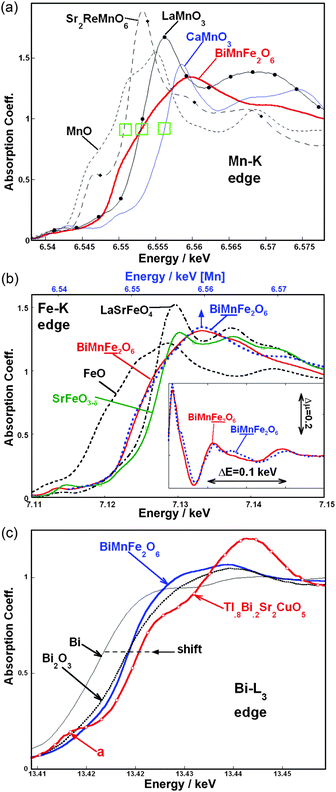 | ||
| Fig. 1 (a) The Mn–K edges for BiMnFe2O6 along with the Mn2+ (MnO, Sr2ReMnO6), Mn3+ (LaMnO3), and Mn4+ (CaMnO3) standards. The green rectangles indicate the chemical shift between Mn2+. Mn3+, and Mn4+; (b) The Fe–K edges for BiMnFe2O6 along with the Fe2+ (FeO), Fe3+ (LaSrFeO4) and ∼Fe4+ (SrFeO3 − δ) standards. For comparison the Mn–K edge for BiMnFe2O6 has been plotted (top scale). The energy range for the Mn–K edge is the same as in the Fe case and the spectra have been aligned such that maximum peak in the MnO and FeO spectra coincide. Inset: an expanded view of the absorption coefficient oscillations above the main peak of the Fe- and Mn–K edge spectra of BiMnFe2O6 in the main figure. Here the monoxide based scale alignment is again used; (c) The Bi-L3 edges for BiMnFe2O6 along with the elemental Bi, and Bi3+ (Bi2O3) standards. The Tl0.8Bi0.2Sr2CuO5 compound provides an example of the spectral modifications due to an admixture of Bi5+ (Bi-6s-hole creation). | ||
In Fig. 1b the Fe–K edge for BiMnFe2O6 is compared to the Fe2+ (Fe2+O), Fe3+ (LaSrFeO4) and ∼Fe4+ (SrFeO3 − δ) standards.37 Again the crossing point between the BiMnFe2O6 and the LaSrFe3+O4 standard supports the Fe3+ character in the former. The 57Fe Mössbauer spectroscopy (shown later) provides a convincing confirmation of this assignment.
There is a strong similarity between the Mn- and Fe–K edge spectra for BiMnFe2O6. To illustrate this point the Mn–K spectrum is plotted in Fig. 1b (top scale) with the FeO and MnO energies aligned and with the same 40 eV plot-interval. The same broad rise and peak structures are observed in both the Mn and Fe spectra. The Mn-edge does appear to have some additional sharper features. The similarity of the Mn and Fe spectra is underscored in the inset of Fig. 1b, where the two spectra are superimposed over ∼ 200 eV above the main peak at the edge. This similarity supports the rather similar random distribution of the Fe and Mn over the two transition metal sites in the BiMnFe2O6 structure.
In view of the relevance of the Bi3+ lone pair we compare the Bi-L3 edge of BiMnFe2O6 to standard spectra in Fig. 1c. The chemical shift of the main edge to higher energy, with increasing Bi valence (between Bi, Bi2O3, and Tl0.8Bi0.2Sr2CuO5), can be seen along the dashed line in the figure. Here Tl0.8Bi0.2Sr2CuO5 was previously shown to have a Bi5+ admixture.38,39 The appearance of pre-edge a-feature (indicated in Fig. 1c) in the Tl0.8Bi0.2Sr2CuO5 spectrum is characteristic of the 6s-hole creation which accompanies the Bi5+ state.38–40 This a-feature has been attributed to dipole allowed 2p → 6s transitions which open up as the Bi valence rises above Bi3+. The important points to note for the present work are: 1) the chemical shift of the BiMnFe2O6 is comparable to Bi2O3 indicating the Bi3+ state; 2) the a-feature is absent from the BiMnFe2O6 spectrum indicating a filled 6s2 state characteristic of Bi3+. Thus the Bi-L3 edge measurements unambiguously confirm the Bi3+ state for BiMnFe2O6.
Determination of the crystal structure
The room temperature PXD pattern of BiMnFe2O6 can be indexed with the orthorhombic unit cell: a = 5.03588(2), b = 7.07341(4), c = 12.65416(6) Å. The systematic absences narrow the possible space group to Pbc21 (No. 29) or Pbcm (No. 57). The selected area electron diffraction (SAED) patterns of three main zones of BiMnFe2O6 (Fig. 2) can be indexed with the given lattice parameters and exhibit reflection conditions hkl: no conditions, hk0: no conditions, h0l: l = 2n, 0kl: k = 2n, which are in agreement with the Pbc21 and Pbcm space groups. Therefore to decide between these two space groups, convergent beam electron diffraction (CBED) experiments were conducted. As shown in Fig. 3, both the zero order Laue zone pattern and the Whole Pattern (WP) of BiMnFe2O6 taken along the [010] zone axis show symmetry m2m, which is in agreement with the centrosymmetric space group Pbcm, but rules out Pbc21.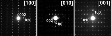 | ||
| Fig. 2 ED pattern along the three main directions of BiMnFe2O6. | ||
![The [010] zero order Laue zone CBED pattern (left) and the [010] Whole Pattern CBED pattern (right) of BiMnFe2O6.](/image/article/2010/SC/c0sc00348d/c0sc00348d-f3.gif) | ||
| Fig. 3 The [010] zero order Laue zone CBED pattern (left) and the [010] Whole Pattern CBED pattern (right) of BiMnFe2O6. | ||
In analyzing the PXD data, we treated Mn and Fe to be identical, because of their similar scattering factors, and since Bi is much heavier than O, we can only locate Bi and Mn/Fe with the direct methods. In the following, a Monte-Carlo based simulated annealing technique was applied with the TOPAS software package41 to find all the oxygen atoms with the PND data. The transition metal cations occupy two crystallographically independent sites 4a and 8e. The multiplicity ratio of these two sites is the same as the atomic Mn/Fe ratio in BiMnFe2O6. However, any attempt to refine the structure with a Mn/Fe ordered model, where Mn and Fe occupies the 4a and 8e site, respectively, resulted in a poor fit of the data. Indeed, Mn3+ and Fe3+ could have similar coordination in solid state oxides, as expected by their similar ionic radii.42 Thus a disordered structure model is more reasonable than an ordered one. Moreover, the successful synthesis of BiMn0.9Fe2.1O6 and BiMn1.1Fe1.9O6, further confirms that Mn and Fe can occupy, at least partially, either of the two crystallographic sites. Because of the negative neutron scattering length of Mn (Mn: -0.373; Fe: 0.945; O: 0.5803; Bi: 0.8532) and the large difference between the scattering lengths of Mn and Fe, relatively accurate occupancies of Mn and Fe can be obtained from the refinement of the PND data. The refinement of the occupancy factors revealed that the 4a and 8e positions contain 39.0(4)% and 29.7(3)% of Mn, respectively, that agrees with the bulk composition of the sample and the results of EDX analysis in the range of standard deviation. The final refinement was performed using both PXD and NPD data sets with the JANA2006 program package.43 For the final refinement the occupancy factors of the 4a and 8e positions were set as g(4a) = 0.4Mn + 0.6Fe and g(8e) = 0.3Mn + 0.7Fe that did not influence the reliability factors. Fig. 4 shows the profile fitting for the PXD and PND patterns, respectively. In Table 1, the crystallographic parameters and refinement results are presented. The atomic coordinates, and selected metal-oxygen bond lengths of BiMnFe2O6 are shown in Table 2 and 3, respectively. Further details on the crystal structural investigations may be obtained from the Fachinformationszentrum Karlsruhe, 76344 Eggenstein-Leopoldshafen, Germany (fax: (+ 49) 7247-808-666; e-mail: crysdata@fiz-karlsruhe.de), on quoting the depository number CSD-421381.
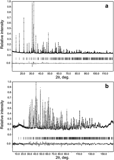 | ||
| Fig. 4 Experimental, calculated and difference powder X-ray diffraction (a) and neutron diffraction patterns (b) after the Rietveld refinement. The marks below the diffraction patterns are the expected reflection positions. | ||
| Crystallographic data | ||
|---|---|---|
| Formula | BiMnFe2O6 | |
| Color | Gray | |
| Formula mass | 471.62 | |
| Space group | Pbcm (No. 57) | |
| a/Å | 5.03590(3) | |
| b/Å | 7.07342(4) | |
| c/Å | 12.65425(6) | |
| V/Å3 | 450.757(6) | |
| Z | 4 | |
| ρ c/g cm−3 | 6.947 | |
| Refinement data | ||
| Radiation | Neutron | X-ray |
| λ/Å | 1.5402 | 1.540596 |
| 2θ/degree | 3∼167.75 | 10.007∼119.987 |
| Step size | 0.05 | 0.013 |
| RF | 0.034 | 0.039 |
| Rp | 0.041 | 0.024 |
| Rwp | 0.052 | 0.032 |
| Atom | site | x/a | y/b | z/c | Uiso/Å2 | Occu. |
|---|---|---|---|---|---|---|
| Bi | 4d | 0.9705(1) | 0.3695(1) | 1/4 | 0.0063(2) | 1 |
| Mn1 | 8e | 0.4891(3) | 0.3403(2) | 0.60356(7) | 0.0078(3) | 0.3 |
| Fe1 | 0.7 | |||||
| Mn2 | 4a | 0 | 1/2 | 1/2 | 0.0032(5) | 0.4 |
| Fe2 | 0.6 | |||||
| O1 | 8e | 0.1628(4) | 0.9371(3) | 0.6366(2) | 0.0063(5) | 1 |
| O2 | 8e | 0.6640(4) | 0.0924(4) | 0.5765(2) | 0.0094(5) | 1 |
| O3 | 4c | 0.7913(6) | 3/4 | 1/2 | 0.0086(7) | 1 |
| O4 | 4d | 0.3450(7) | 0.1977(4) | 1/4 | 0.0068(7) | 1 |
| Bond | Length | Bond | Length | Bond | Length |
|---|---|---|---|---|---|
| Bi–O1(×2) | 2.206(2) | M1–O1 | 1.928(3) | M2–O1(×2) | 1.965(2) |
| Bi–O4 | 2.243(3) | M1–O2 | 1.973(3) | M2–O2(×2) | 2.056(2) |
| Bi–O1(×2) | 2.685(2) | M1–O2 | 1.992(3) | M2–O3(×2) | 2.057(2) |
| Bi–O2(×2) | 2.697(2) | M1–O4 | 2.008(2) | ||
| Bi–O4 | 2.813(3) | M1–O3 | 2.029(3) | ||
| M1–O2 | 2.489(2) |
Description of the crystal structure
In spite of the exact 1:2 Mn/Fe ratio, the Mn3+ and Fe3+ cations are disordered over two crystallographically distinct M1 and M2 positions in the structure. The position M1 has a pseudo-octahedral environment with five short bonds varying from 1.928(3) to 2.029(3) Å and one elongated bond of 2.489(2) Å, while M2 is a relatively regular octahedral site with 2 short (1.965(2) Å) and 4 long (2.056(2), 2.057(2) Å) metal-oxygen bonds (Fig. 5a). Thus the coordination environment of the M1 cations is better described as M1O5 + 1. It should be noted that such coordination is suitable for both the Mn3+ and Fe3+ cations. The former demonstrates the tendency to a Jahn–Teller distortion due to its d4 electronic configuration, whereas the spherically symmetric d5 shell of the latter allows it to adopt the range of coordination numbers from 4 to 6. The overall structural views along the a- and b-axes (Fig. 5b and 5c) indicate a framework composed of M1O5 + 1 and M2O6 octahedra with the Bi3+ cations in the cavities.
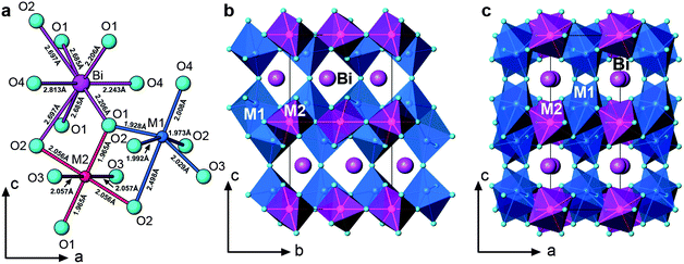 | ||
| Fig. 5 (a) Local coordination environments of metal cations; (b) structure view along the a-axis; (c) structure view along the b-axis. | ||
The M1O5 + 1 octahedra are interconnected and form an infinite layer in the bc-plane (Fig. 5b and 6a). All three types of connections, corner-, edge-, and face-sharing, are present between the M1O5 + 1 octahedra. As shown in Fig. 6a, two M1O5 + 1 units share faces to form a dimer. Each dimer further connects to two neighbouring dimers by edge-sharing along the b-axis and another two by corner-sharing along the c-axis. The connection between M2O6 is simpler (Fig. 6b); they corner-share to form one-dimensional infinite zig-zag chains along the b-axis, separating the layers of the M1O5 + 1 units.
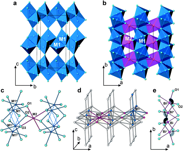 | ||
| Fig. 6 (a) Dimers of two face-shared M1O5 + 1 polyhedra interconnected to form an infinite layer in the bc-plane; (b) the M1O5 + 1 infinite layers (blue) are separated by M2O6 zig-zag chains (red), where the M2O6 are corner-shared along the b-axis; (c) the local connectivity between M1O5 + 1 and M2O6 octahedra: the distances between the metal sites are M1a-M2, 3.083 Å; M1b-M2, 3.690 Å; M1c-M2, 3.749 Å; M1-M2, 3.010 Å; (d) transition metal backbone of BiMnFe2O6. Each M1 connects to 5 M1 and 4 M2. Each M2 connects to 8 M1 and 2 M2; (e) arrangement of the stereoactive lone pairs of Bi3+, visualized with ELF isosurfaces at η = 0.75. Symmetry transformations used to generate equivalent atoms: a -x, y + 1/2, z; b x, 1/2-y, -z; c -x, -y, -z. | ||
In contrast, the connections between M1- and M2-centered octahedra are much more complicated. One M2O6 is linked with eight M1O5 + 1 octahedra via corner- and edge-sharing. As shown in Fig. 6c, there are four different distances between two transition metal sites: M1a-M2, 3.083 Å; M1b-M2, 3.690 Å; M1c-M2, 3.749 Å; M1-M2, 3.010 Å. Fig. 6d is a scheme of the transition metal backbone in BiMnFe2O6, where each M1 is surrounded by 5 M1 and 4 M2, while each M2 is surrounded by 8 M1 and 2 M2.
In spite of the great complexity, the relationship of BiMnFe2O6 with some simple parent structure arrangement can be established. When viewing the BiMnFe2O6 structure along the a-axis (Fig. 5b), one can separate the octahedral blocks running along the b-axis and connected by corner sharing along the c-axis. Oxygen atoms in these blocks form a close packed motif, where the M1 and M2 cations occupy the octahedral interstices. The presence of face-sharing between pairs of the M1O5 + 1 distorted octahedra implies that these blocks are cut from an hcp structure. One may assume that known hcp-based oxide structures with incomplete filling of the octahedral interstices could serve as the prototype, but careful comparison of the cation arrangement in the octahedral interstices reveals that it is not the case, because the presence of cation vacancies at the vacant octahedral interstices does not match with the positions of the M1 and M2 cations in BiMnFe2O6. However, the close packed blocks in BiMnFe2O6 can be cut from a hypothetical hcp structure with MO composition (NiAs structure type), i.e. with the octahedral interstices completely filled. In the hcp structure, as shown in Fig. 7a and 7b, these blocks are limited by (114)h (h denotes indexes belonging to the hexagonal NiAs-type hcp structure) crystal planes. In BiMnFe2O6 identical blocks, perpendicular to the c axis are embedded in the crystal lattice (Fig. 7c). The identity of the atomic arrangement in the (114)h close packed blocks in the hcp structure and in BiMnFe2O6 is seen from a comparison of Fig. 7d and 7e. In the BiMnFe2O6 structure the blocks are stacked along the c axis related by the mirror planes of the Pbcm space group and share octahedral corners at these planes. Thus, BiMnFe2O6 can be considered as a derivative of the hcp MO structure arising from a periodical mirror twinning along the (114)h planes (polysynthetic twinning). The Bi atoms occupy the interstices formed at the twin boundaries. The relationship between BiMnFe2O6 and the parent hcp structure is supported by the high resolution transmission electron microscopy image (Fig. 7f). The [100] HRTEM image corresponds to the structure projection given in Fig. 7c. The experimental image clearly shows the polysynthetically twinned hcp MO structure with twinned lamellae separated by equidistant mirror planes (marked by arrows). On this image the columns of cations correspond to the black dots, with the bismuth columns located in the black dots at the mirror planes. This interpretation is supported by the excellent agreement between the experimental image and the calculated image (f = −400 Å, t = 30 Å), superimposed onto the experimental image and indicated with white brackets (Fig. 7f).
![(a) A hypothetic hcp MO structure with the close packed blocks marked (dashed lines) with the traces of (114) crystal planes; (b) the (114)-shaped blocks cut out of the hcp MO structure; (c) stacking of the hcp blocks in the BiMnFe2O6 structure; (d) top view on the (114)-shaped block in the hcp MO structure; (e) [001] projection of the hcp block in the BiMnFe2O6 structure. To make the comparison easier, the octahedra around the M1 and M2 cations in BiMnFe2O6 are drawn in the same color; (f) HRTEM image of BiMnFe2O6 along the [100] direction. The calculated image is superimposed and marked with white brackets. The best agreement with the experimental image was found at focus value −400 Å and thickness 30 Å. On this image the columns of cations correspond to the black dots, with the Bi columns being located in the black dots at the mirror planes. The mirror planes are marked with arrows.](/image/article/2010/SC/c0sc00348d/c0sc00348d-f7.gif) | ||
| Fig. 7 (a) A hypothetic hcp MO structure with the close packed blocks marked (dashed lines) with the traces of (114) crystal planes; (b) the (114)-shaped blocks cut out of the hcp MO structure; (c) stacking of the hcp blocks in the BiMnFe2O6 structure; (d) top view on the (114)-shaped block in the hcp MO structure; (e) [001] projection of the hcp block in the BiMnFe2O6 structure. To make the comparison easier, the octahedra around the M1 and M2 cations in BiMnFe2O6 are drawn in the same color; (f) HRTEM image of BiMnFe2O6 along the [100] direction. The calculated image is superimposed and marked with white brackets. The best agreement with the experimental image was found at focus value −400 Å and thickness 30 Å. On this image the columns of cations correspond to the black dots, with the Bi columns being located in the black dots at the mirror planes. The mirror planes are marked with arrows. | ||
It is well known that many MO (M – transition metals, alkali-earth metals) oxides have a close packed structure, but they all are based on a ccp arrangement of oxygen atoms, where the metal atoms occupy all octahedral interstices. The hcp MO octahedral structure has not been observed so far. Surprisingly, the close packed blocks in BiMnFe2O6 adopt such a hcp structure, rather than the ccp structure. To the best of our knowledge, BiMnFe2O6 is the first example with fragments of the hcp oxygen-based structure serving as the building modules in a complex transition metal oxide. Note that modules of the hcp structure frequently occur in hexagonal perovskites, where however the close packed layers have a mixed AO3 composition (A – a relatively large cation); while in BiMnFe2O6 the close packing is formed by the oxygen atoms only. It should be noted, however, that a strongly distorted ccp-based perovskite ABO3 structure can be also considered as a virtual derivative of the periodically twinned hcp structure, as suggested by Hyde and Andersson1 for the GdFeO3-type ferrites, particularly for LuFeO3.44 Because of strong cooperative tilting distortion of the perovskite octahedral framework, the (112)-shaped hcp-type single octahedral layers can be selected in this structure, when viewed along the [110] direction of the perovskite subcell. However, in contrast to BiMnFe2O6, this representation of distorted perovskite as a layered hcp structure is purely formal, because the corner sharing connectivity remains between the octahedral units within the layer and between the layers, and no edge- and face-sharing occur as in the hcp modules of the BiMnFe2O6 structure.
The BiMnFe2O6 structure inspires a new building mechanism, based on cutting blocks of the hcp MO structure along selected crystal planes, stacking these blocks together by periodical twinning and filling the interstices between the blocks with cations with a lone electron pair, such as Bi3+ or Pb2+. Lone electron pair cations are known to stabilize the interfaces, which divide inorganic materials into ionic and covalent parts.45 In BiMnFe2O6 the metal–oxygen interactions within the hcp modules and between the modules have the same degree of covalency. Bismuth atoms in BiMnFe2O6 are coordinated by eight oxygen atoms with three short (2.21–2.24 Å) and five long (2.69–2.81 Å) Bi–O bonds. The asymmetric local environment is typical for Bi3+, because of the presence of the lone electron pair. Indeed, the electron localization function (ELF) distribution shows attractors near the Bi atoms. The ELF isosurfaces suggest the localization of the lone pair between the two Bi–O(2) bonds and the two (longer) Bi–O(1) bonds (see Fig. 6e).
The important role of the lone pair cations in the stabilization of planar defects in oxides can also be illustrated by the drastic influence of an isovalent replacement of alkali-earth cations by lone electron pair cations in the A-sublattice of anion deficient perovskites. Sr2Fe2O5 is known to adopt the brownmillerite-type structure, which is an anion deficient perovskite with ordered anion vacancies, creating alternating layers of iron atoms in tetrahedral and octahedral coordination.46 A replacement of Sr2+ by Pb2+ results in a completely different structural realization of the anion deficiency: oxygen vacancies are eliminated by crystallographic shear planes, which is highly unusual for perovskites.47,48 The shear operation involves a displacement of one perovskite module with respect to its counterpart by a 1/2[110] vector of the perovskite subcell and involves removal of oxygen atoms along the interface. The configurational changes at the shear planes are manifested by a formation of six-sided tunnels occupied exclusively by the Pb2+ cations. Similar to the Bi3+ cations in BiMnFe2O6, the Pb2+ cations in these tunnels have an asymmetric coordination with three shorter Pb–O distances (∼ 2.35 Å) and three longer ones (2.70 Å) and their coordination environment is completed by localized lone electron pairs.49,50 Thus it can be concluded that the lone electron pair cations can promote the formation of planar interfaces of different nature, as it is demonstrated by the examples of the twin interfaces in the hcp structure and the translational interfaces in the perovskite structure. Due to the ability of ions with lone electron pair to adopt a strongly asymmetric coordination and variable coordination number, such cations act as “chemical scissors” for the close packed oxides, potentially generating a variety of modular structures.
Magnetism
The 57Fe Mössbauer spectra of BiMnFe2O6 as a function of temperature confirm the trivalent state of iron and suggest an intrinsic magnetic order at 213 ± 2 K (Fig. 8). The spectrum at 210 K exhibits a superposition of both a paramagnetic doublet and a magnetically ordered sextet (44%), indicating a somewhat broad magnetic phase transition. In Table 4, the hyperfine interaction parameters derived from the analysis of the spectra are collected. The spectra above the ordering temperature exhibit a quadrupole doublet composed of symmetric non-Lorentzian broad lines, indicating only a small difference between the electric field gradients in the two “octahedral” crystallographically different locations of the iron ions, unlike in Bi2Mn4 − xFexO10.51 The spectra were analyzed in terms of a Gaussian distribution of the quadrupole splitting, considering the distribution in local environments in which the Fe3+ ions are located. At room temperature the average quadrupole splitting (0.74(1) mm s−1) is very similar to that of the octahedral site (0.72(2) mm s−1) in BiMn4-xFexO10.51 The temperature dependence of the magnetic hyperfine field acting on the iron nuclei is shown in Fig. S1† in the supporting information. The observed distribution of the magnetic hyperfine fields and the very small quadrupole shifts in comparison to the values of the quadrupole splitting above the magnetic ordering temperature indicate that the magnetic order has some level of spin-glass nature. The necessary magnetic frustration is probably due to the distribution in local magnetic anisotropy resulting from the many inequivalent Fe environments, in terms of local magnetic (Mn and Fe) neighbors.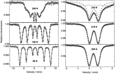 | ||
| Fig. 8 57Fe Mössbauer spectra of BiMnFe2O6 at different temperatures. | ||
| Temp./K | I.S./mm s−1 | ε/mm s−1 | H eff/kOe |
|---|---|---|---|
| 90 | 0.486(7) | 0.022(2) | 459(5) |
| 150 | 0.454(7) | −0.052(5) | 404(5) |
| 200 | 0.430(5) | −0.04(1) | 228(5) |
| I 210 | 0.40(2) | 0 | |
| II (44%) | −0.02(1) | 88(10) | |
| 215 | 0.415(4) | 0.375(1) | |
| 225 | 0.41(1) | 0.373(4) | |
| 295 | 0.369(3) | 0.371(1) |
In Fig. 9a, the temperature-dependent magnetic susceptibilities (χ = M/H) of BiMnFe2O6 show: (i) the magnetic ordering in BiMnFe2O6 as a broad cusp at TN = 212 K; (ii) small susceptibility values below TN, indicating AFM type of the ordering; (iii) an additional feature at 40 K, which will be discussed below. The phase transition at TN is also supported by the temperature-dependent specific heat at an applied magnetic field of 2 T (Fig. 9b). It appears to be a second order transition, consistent with the result of the 57Fe Mössbauer spectra (Fig. 8). The ordering temperature is nearly insensitive to the magnitude of applied magnetic field (H) (see the inset of Fig. 9b), which is expected for an antiferromagnet. The solid solutions, BiMn0.9Fe2.1O6, BiMn1.1Fe1.9O6 (Fig. 9a), exhibit similar AFM order, with TN of 224 and 204 K, respectively (The cell parameters of these phases obtained from the Le Bail fit are given in Fig. S2 and Table S1 in the supporting information†). The isothermal magnetizations (Fig. 9c) are typical of AFM behavior. The magnetization at 1 T and 20 K is far from saturation. Despite the presence of the crystallographic Fe/Mn disorder, the magnetic ordering at TN has long-range nature, which is confirmed by the PND studies.
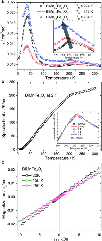 | ||
| Fig. 9 (a) Temperature-dependent magnetic susceptibilities of BiMn0.9Fe2.1O6, BiMnFe2O6, BiMn1.1Fe0.9O6. The inset is the enlargement of the high temperature region; (b) specific heat for BiMnFe2O6 under 2 T, the inset is the normalized magnetic susceptibilities of BiMnFe2O6 under various external fields; (c) isothermal magnetizations for BiMnFe2O6 at different temperatures. | ||
The room temperature PND data show apparent short-range magnetic order (Fig. 10), as suggested by the broad maximum around 15° (2θ). This short-range magnetic order persists even at 400 K (see Fig. S3 in the supporting information†), which is consistent with the inability to fit the magnetic susceptibility data above TN to Curie-Weiss law with reasonable parameters. Additional (magnetic) reflections appear below 215 K in Fig. 10, and the intensity of these reflections increases steadily to 7 K. More than a dozen magnetic reflections are observed, which can be indexed with an incommensurate propagation vector k = [α,0,0], α = 0.1379(1) for the data at 7 K. This approximately corresponds to the commensurate magnetic supercell with am,bm,cm = 7a,b,c, where a,b,c are the lattice parameters of the nuclear structure. No satellite reflections beyond the first-order satellites were observed. The α component of the propagation vector is almost temperature independent in the 7–57 K temperature range and decreases linearly down to α = 0.1155(9) on going towards the Neel temperature (see Fig. S5 in the supporting information†). The formation of the incommensurate magnetic structure is likely caused by the magnetic frustration that arises in the complex transition-metal backbone of BiMnFe2O6 (Fig. 6d). An accurate magnetic structure will be published later.
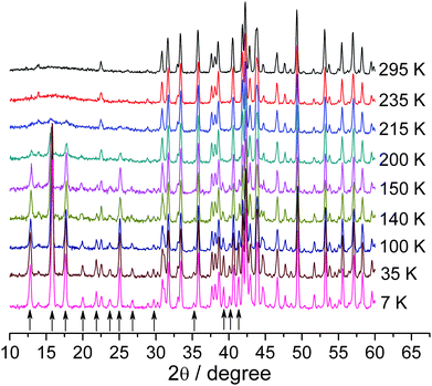 | ||
| Fig. 10 Neutron diffraction patterns for BiMnFe2O6 at different temperatures. The arrows under the curves show the magnetic reflections. | ||
In addition to the cusp at TN, the magnetic susceptibility curves show a pronounced anomaly at T* = 36–38 K (Fig. 9a). The magnitude of this anomaly depends on the Mn/Fe ratio. However, neither the specific heat (Fig. 9b), nor PND (Fig. 10) show any anomaly or change at T*. The origin of the magnetic susceptibility anomaly at T* is presently unclear. This anomaly could be caused by impurities. However, the magnitude of the anomaly is too large to be accounted by a few percent of an impurity phase, while our X-ray and neutron diffraction (nor the EDAX) studies do not show any crystalline impurities in the samples under investigation. Thus, an intrinsic nature of this anomaly is more likely. One should keep in mind that different methods have limited sensitivity to magnetic ordering and magnetic transitions in frustrated spin systems. Both neutron diffraction and specific heat readily detect long-range ordering, but they are rather insensitive to changes in short-range ordering. Nevertheless, such changes affect magnetic susceptibility. We propose that the anomaly at 36–38 K corresponds to some effects on a small length scale (e.g., magnetic phase separation). These effects require further investigation with the appropriate methods, such as muon spin rotation and resonant X-ray scattering.
While the low-temperature anomaly lacks detailed explanation, our data is consistent with long-range AFM ordering in BiMnFe2O6 at TN = 212 K. The coincidence of the FC and ZFC susceptibility curves below TN (down to T* in Fig. S5 in the supporting information†) shows the absence of spin-freezing effects, despite the inherent crystallographic disorder in the compound under investigation. The robust magnetic ordering is an important feature of BiMnFe2O6, which may be important for potential applications.
Transport and dielectric properties
In Fig. 11, the temperature variation of the resistivity of BiMnFe2O6 with FC and ZFC shows semiconducting behavior above 285 K. The resistivity at room temperature is high, 106 Ω.cm; below 285 K, the signal is out of the range of the measuring device. The estimated activation energy (Ea) is ∼0.43 eV and 0.41 eV with and without the magnetic field, respectively, which is typical for semiconductors. A positive magnetoresistivity is also observed, which rises from almost zero to 16%/1T at around 340 K (Fig. 11). The mechanism of this small magnetoresistivity remains open. However, due to the polycrystalline character of the samples, grain-boundary effects which give rise for additional resistive contributions have to be considered as it is denoted by the dielectric measurements discussed in the following.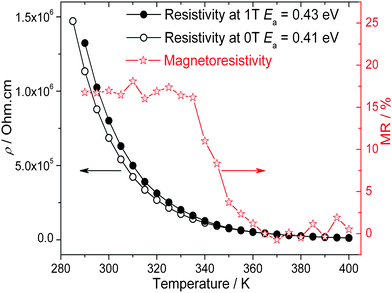 | ||
| Fig. 11 Resistivity of BiMnFe2O6 with and without an external magnetic field (1 T). | ||
The dielectric permittivity decreases monotonously from a high value (∼2000) at room temperature to about 30 at 50 K (Fig. 12). However, this high temperature value is strongly frequency dependent as illustrated by the exemplary curves shown in Fig. 12. Such high values can be explained as contributions from highly capacitive depletion layers formed between the sample and electrodes (or even sample inhomogeneities as e.g. grain boundaries).52 The resulting effective RC-element in series to the intrinsic resistivity enhances the resistivity and gives an additional capacitive contribution for low enough frequencies. For higher frequencies this effective RC contribution is shortcut and the intrinsic material properties prevail. For these no anomaly is detected, indicating that BiMnFe2O6 is paraelectric in the temperature range around the magnetic transition. The intrinsic permittivity is ∼20. The high values of the loss factor tanδ seen at higher temperatures are due to the residual conductivity contributions. At low temperatures (and higher frequencies) the conductivity is enhanced by hopping processes typical for such disordered semiconductors.52
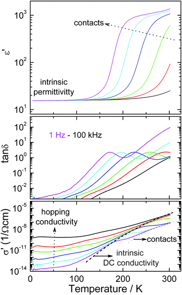 | ||
| Fig. 12 Dielectric permittivity, energy loss and conductivity of BiMnFe2O6 as a function of temperature. | ||
Conclusion
BiMnFe2O6 was synthesized by a simple solid state reaction in air. The structure determined by powder diffraction methods is composed of MnO6, FeO6 and BiO8 polyhedra. The structure of BiMnFe2O6 is the first example, with fragments of the hcp MO structure as the building blocks in complex transition metal oxides. The diversity of metal–oxygen–metal interaction paths (through corner-, edge- or face-sharing units) in such oxides leads to magnetic frustration and incommensurate magnetic ground states at 212 K that opens an alternative route to multiferroicity.53–56 However, the transport and dielectric properties, measured down to low temperatures, indicate that BiMnFe2O6 is semiconducting and paraelectric below TN. Nevertheless, the unique structure of BiMnFe2O6 inspires further studies to achieve multiferroic behavior by designing new compositions based on the ability of Bi3+ and Pb2+ to stabilize novel phases with hcp MO building blocks. Further studies are being pursued to improve its property. Preliminary substitutions by aliovalent ions including Na+, Ca2+, Sr2+ for Bi3+ and Mg2+, Cu2+, Zn2+, Ti4+ for the transition metals are expected to change the valence state of Mn3+ and/or Fe3+ possibly resulting in inhomogenous magnetism similar to that in doped Mn-perovskites with colossal magnetoresistance.57,58 Initial results of Mg2+-, Cu2+- and Zn2+-doped BiMnFe2O6 show weak ferromagnetism at room temperature, which may be due to Mn3+-Mn4+ ferromagnetic double-exchange. High pressure methods are underway for the synthesis of AM3O6 with A = Bi3+, Pb2+and M = Cr, Mn, Fe, Co where displacement of A ions off the mirror plane could lead to polar structures with multiferroic properties.Acknowledgements
Contributions by Dr Judith Stalick of NIST, and Professors Rolfe Herber (Racah Institute, Hebrew University-Jerusalem) and Ashok Ganguly, IIT-New Delhi, India) are gratefully acknowledged. This work was partially supported by NSF-DMR 0541911 grant (MG, TY). J.H., A.M.A. and G.V.T. acknowledge financial support from the European Union under the Framework 6 program under a contract for an Integrated Infrastructure Initiative. Reference 026019 ESTEEM. A.M.A. is grateful to the Russian Foundation of Basic Research (RFBR Grant 07-03-00664-a) for the financial support. SEL acknowledges support from NSF MRSEC DMR 0520471. Use of the National Synchrotron Light Source, Brookhaven National Laboratory, was supported by the U.S. Department of Energy, Office of Basic Energy Sciences, under Contract No. DE-AC02-98CH10886.Notes and references
- B. G. Hyde, and S. Andersson, Inorganic crystal structures. (Chichester, England and New York: John Wiley, 1989) Search PubMed.
- K. Aurivillius, Acta Chem. Scand., 1964, 18, 1305–1306 CrossRef CAS.
- R. H. Mitchell, Perovskites: Modern and Ancient. (Almaz Press Inc., Thunder Bay, Canada, 2002) Search PubMed.
- C. N. R. Rao, and B. Raveau, Transition metal oxides. (VCH Publishers, New York, 1995) Search PubMed.
- G. Ferraris, E. Makovicky, S. Merlino, Crystallography of Modular Materials, (Oxford University Press, 2004) Search PubMed.
- P. Bordet, C. Bougerol Chaillout, I. E. Grey, J. L. Hodeau and O. Isnard, J. Solid State Chem., 2000, 152, 546–553 CrossRef CAS.
- L. Farber, I. Levin, A. Borisevich, I. E. Grey, R. S. Roth and P. K. Davies, J. Solid State Chem., 2002, 166, 81–90 CrossRef CAS.
- S. Andersson and L. Jahnberg, Ark. Kemi., 1963, 21, 413–26 Search PubMed.
- J. Darriet and M. A. Subramanian, J. Mater. Chem., 1995, 5, 543–552 RSC.
- N. A. Hill, J. Phys. Chem. B, 2000, 104, 6694–6709 CrossRef CAS.
- W. Eerenstein, N. D. Mathur and J. F. Scott, Nature, 2006, 442, 759–765 CrossRef CAS.
- T. Kimura, Annu. Rev. Mater. Res., 2007, 37, 387–416 CrossRef CAS.
- C. N. R. Rao and C. R. Serrao, J. Mater. Chem., 2007, 17, 4931–4938 RSC.
- S. W. Cheong and M. Mostovoy, Nat. Mater., 2007, 6, 13–20 CrossRef CAS.
- D. Khomskii, Physics, 2009, 2, 20 Search PubMed.
- J. Wang, J. B. Neaton, H. Zheng, V. Nagarajan, S. B. Ogale, B. Liu, D. Viehland, V. Vaithyanathan, D. G. Schlom, U. V. Waghmare, N. A. Spaldin, K. M. Rabe, M. Wuttig and R. Ramesh, Science, 2003, 299, 1719–1722 CrossRef CAS.
- J. Dho, X. Qi, H. Kim, J. L. MacManus-Driscoll and M. G. Blamire, Adv. Mater., 2006, 18, 1445–1448 CrossRef CAS.
- T. Kimura, S. Kawamoto, I. Yamada, M. Azuma, M. Takano and Y. Tokura, Phys. Rev. B: Condens. Matter Mater. Phys., 2003, 67, 180401 CrossRef.
- J. Y. Son, B. G. Kim, C. H. Kim and J. H. Cho, Appl. Phys. Lett., 2004, 84, 4971–4973 CrossRef CAS.
- C. H. Yang, J. Koo, C. Song, T. Y. Koo, K. B. Lee and Y. H. Jeong, Phys. Rev. B: Condens. Matter Mater. Phys., 2006, 73, 224112 CrossRef.
- C. Vecchini, L. C. Chapon, P. J. Brown, T. Chatterji, S. Park, S. W. Cheong and P. G. Radaelli, Phys. Rev. B: Condens. Matter Mater. Phys., 2008, 77, 134434 CrossRef.
- N. Imamura, M. Karppinen, T. Motohashi, D. Fu, M. Itoh and H. Yamauchi, J. Am. Chem. Soc., 2008, 130, 14948–14949 CrossRef CAS.
- A. A. Belik and E. Takayama-Muromachi, J. Am. Chem. Soc., 2009, 131, 9504–9505 CrossRef CAS.
- J. B. Claridge, H. Hughes, C. A. Bridges, M. Allix, M. R. Suchomel, H. J. Niu, X. J. Kuang, M. J. Rosseinsky, N. Bellido, D. Grebille, O. Perez, C. Simon, D. Pelloquin, S. J. Blundell, T. Lancaster, P. J. Baker, F. L. Pratt and P. Shiv Halasyamani, J. Am. Chem. Soc., 2009, 131, 14000–14017 CrossRef CAS.
- A. Savin, R. Nesper, S. Wengert and T. E. Fassler, Angew. Chem., Int. Ed. Engl., 1997, 36, 1808–1832 CrossRef CAS.
- G. Krier, O. Jepsen, A. Burkhart, O. K. Andersen, The TB-LMTO-ASA Program, Stuttgart, 1995 Search PubMed.
- U. von Barth and L. Hedin, J. Phys. C: Solid State Phys., 1972, 5, 1629–1642 CrossRef.
- N. A. Hill and K. M. Rabe, Phys. Rev. B: Condens. Matter Mater. Phys., 1999, 59, 8759–8769 CrossRef.
- K. Masuno, Nippon Kagaku Zasshi, 1967, 88, 726–730 CAS.
- G. Huo, Z. Gu and M. Qiu, J. Alloys Compd., 2004, 381, 317–319 CrossRef CAS.
- T. Atou, H. Chiba, K. Ohoyama, Y. Yamaguchi and Y. Syono, J. Solid State Chem., 1999, 145, 639–642 CrossRef CAS.
- A. A. Belik, H. Yusa, N. Hirao, Y. Ohishi and E. Takayama-Muromachi, Inorg. Chem., 2009, 48, 1000–1004 CrossRef CAS.
- A. A. Belik, T. Kolodiazhnyi, K. Kosuda and E. Takayama-Muromachi, J. Mater. Chem., 2009, 19, 1593–1600 RSC.
- D. M. Giaquinta and H. C. zur Loye, J. Alloys Compd., 1992, 184, 151–160 CAS.
- M. Croft, D. Sills, M. Greenblatt, C. Lee, S. W. Cheong, K. V. Ramanujachary and D. Tran, Phys. Rev. B: Condens. Matter, 1997, 55, 8726–8732 CrossRef CAS.
- G. Popov, M. Greenblatt and M. Croft, Phys. Rev. B: Condens. Matter Mater. Phys., 2003, 67, 024406 CrossRef.
- I. Fawcett, G. Veith, M. Greenblatt, M. Croft and I. Nowik, Solid State Sci., 2000, 2, 821–831 CrossRef CAS.
- S. Li, M. Greenblatt, Y. Jeon, J. Chen and M. Croft, Phys. C, 1991, 173, 239 CrossRef CAS.
- G. Liang, A. Sahiner, M. Croft, J. Chen, J. Peng, X. D. Xiang, A. Zettl and F. Lu, Phys. Rev. B: Condens. Matter, 1993, 47, 1029–1035 CrossRef CAS.
- S. M. Heald, D. DiMarzio, M. Croft, M. S. Hegde, S. Li and M. Greenblatt, Phys. Rev. B: Condens. Matter, 1989, 40, 8828–8833 CrossRef CAS.
- TOPAS V2.1: General Profile and Structure Analysis Software for Powder Diffraction Data; Bruker AXS, Karlsruhe, Germany Search PubMed.
- R. D. Shannon, Acta Crystallogr., Sect. A: Cryst. Phys., Diffr., Theor. Gen. Crystallogr., 1976, 32, 751–767 CrossRef.
- V. Petricek; M. Dusek. JANA2000: Programs for Modulated and Composite Crystals; Institute of Physics: Praha, Czech Republic, 2000 Search PubMed.
- M. Marezio, J. P. Remeika and P. D. Dernier, Acta Crystallogr., Sect. B: Struct. Crystallogr. Cryst. Chem., 1970, 26, 2008–2022 CrossRef CAS.
- Z. Mayerova, M. Johnsson and S. Lidin, Angew. Chem., Int. Ed., 2006, 45, 5602–5606 CrossRef CAS.
- H. D'Hondt, A. M. Abakumov, J. Hadermann, A. S. Kalyuzhnaya, M. G. Rozova, E. V. Antipov and G. Van Tendeloo, Chem. Mater., 2008, 20, 7188–7194 CrossRef CAS.
- A. M. Abakumov, J. Hadermann, S. Bals, I. V. Nikolaev, E. V. Antipov and G. Van Tendeloo, Angew. Chem., Int. Ed., 2006, 45, 6697–6700 CrossRef CAS.
- A. M. Abakumov, J. Hadermann, G. V. Tendeloo and E. V. Antipov, J. Am. Ceram. Soc., 2008, 91, 1807–1803 CrossRef CAS.
- V. Raynova-Schwarten, W. Massa and D. Babel, Z. Anorg. Allg. Chem., 1997, 623, 1048–1054 CrossRef CAS.
- I. V. Nikolaev, H. D'Hondt, A. M. Abakumov, J. Hadermann, A. M. Balagurov, I. A. Bobrikov, D. V. Sheptyakov, V. Y. Pomjakushin, K. V. Pokholok, D. S. Filimonov, G. Van Tendeloo and E. V. Antipov, Phys. Rev. B: Condens. Matter Mater. Phys., 2008, 78, 024426 CrossRef.
- N. Nguyen, M. Legrain, A. Ducouret and B. Raveau, J. Mater. Chem., 1999, 9, 731–734 RSC.
- P. Lunkenheimer, V. Bobnar, A. V. Pronin, A. I. Ritus, A. A. Vlokov and A. Loidl, Phys. Rev. B: Condens. Matter Mater. Phys., 2002, 66, 052105 CrossRef.
- T. Kimura, T. Goto, H. Shintani, K. Ishizaka, T. Arima and Y. Tokura, Nature, 2003, 426, 55–58 CrossRef CAS.
- R. Kajimoto, H. Yoshizawa, H. Shintani, T. Kimura and Y. Tokura, Phys. Rev. B: Condens. Matter Mater. Phys., 2004, 70, 012401 CrossRef.
- M. Kenzelmann, A. B. Harris, S. Jonas, C. Broholm, J. Schefer, S. B. Kim, C. L. Zhang, S. W. Cheong, O. P. Vajk and J. W. Lynn, Phys. Rev. Lett., 2005, 95, 087206 CrossRef CAS.
- N. Hur, S. Park, P. A. Sharma, J. S. Ahn, S. Guha and S. W. Cheong, Nature, 2004, 429, 392–395 CrossRef CAS.
- J. Burgy, M. Mayr, V. Martin-Mayor, A. Moreo and E. Dagotto, Phys. Rev. Lett., 2001, 87, 277202 CrossRef CAS.
- C. Chiorescu, J. J. Neumeier and J. L. Cohn, Phys. Rev. B: Condens. Matter Mater. Phys., 2006, 73, 014406 CrossRef.
Footnote |
| † Electronic supplementary information (ESI) available: Temperature dependence of the magnetic hyperfine field. Neutron diffraction at 375 and 400 K. ZFC and FC susceptibility v.s. T. Rietveld refinements for BiMn0.9Fe2.1O6, BiMn1.1Fe1.9O6. CCDC reference numbers 790422. For ESI and crystallographic data in CIF or other electronic format see DOI: 10.1039/c0sc00348d |
| This journal is © The Royal Society of Chemistry 2010 |