Zn-doped nanocrystalline TiO2 films for CdS quantum dot sensitized solar cells
Guang
Zhu
a,
Zujun
Cheng
a,
Tian
Lv
a,
Likun
Pan
*a,
Qingfei
Zhao
b and
Zhuo
Sun
a
aEngineering Research Center for Nanophotonics and Advanced Instrument, Ministry of Education, Department of Physics, East China Normal University, Shanghai, China. E-mail: lkpan@phy.ecnu.edu.cn; Fax: +86 21 62234321; Tel: +86 21 62234132
bChemistry Department, Shanghai Normal University, Shanghai, China
First published on 20th May 2010
Abstract
Quantum dot-sensitized solar cells based on Zn-doped TiO2 (Zn-TiO2) film photoanode and polysulfide electrolyte were fabricated. Zn-TiO2 nanoparticles were obtained via a hydrothermal method and screen printed on the fluorine-doped tin oxide glass to prepare the photoanode. The structure, morphology and impedance of the Zn-TiO2/CdS film and the photovoltaic performance of the Zn-TiO2/CdS cell were investigated. It was found that the photovoltaic efficiency was improved by 24% when the Zn-TiO2 film was adopted as the photoanode of CdS QDSSCs instead of only the TiO2 layer. The improvement was ascribed to the reduction of electron recombination and the enhancement of electron transport in the TiO2 film by Zn doping.
Introduction
Sensitized solar cells (SSCs) have attracted considerable attention and represent a key class of cell architecture that has emerged as a promising candidate for the development of next generation solar cells due to their acceptable power conversion efficiency and low production cost.1,2 SSCs are based on the photosensitization of semiconductor photoanodes, typically nanocrystalline TiO2, by absorbed dye or quantum dot sensitizers. The electron transport in a semiconductor medium, is thus the key for device performance. It is known that the doping of metal ions into semiconductor materials is a common approach for tailoring properties such as Fermi level, band gap or electric conductivity for specific applications.3–7 Many studies have been devoted to applying metal ion doped TiO2 electrodes in dye SSCs (DSSCs). Ko et al.8 synthesized Al-doped and W-doped TiO2 electrodes for DSSCs and found that the cells exhibited an enhanced conversion efficiency due to decreased recombination between excited and transferred electrons and tri-iodide ions through electrical surface-state modifications by metal-ion dopants. Kim et al.9 deposited Cr-doped TiO2 on a pure TiO2 layer and found that conversion efficiency was improved by 18.3% when the double layer was adopted as the photoanode of a DSSC instead of only the TiO2 layer. They ascribed the improvement to the repression of electron recombination occurring in the double layer. Wang and Teng10 doped Zn ion into a nanocrystalline TiO2 film to enhance electron mobility in DSSCs and an improvement of conversion efficiency by 23% was achieved. Feng et al.4 presented the synthesis of TiO2 nanowire arrays doped with Ta ion for DSSCs and a very high open-circuit voltage of 0.87 V was achieved due to the modification of the band potential of TiO2 by Ta doping. Wijayarathna et al.11 studied DSSCs made from Cu-doped TiO2 films and found that Cu doping shifted the flat-band potential of TiO2 in the negative direction and thus enhanced the open-circuit voltage and conversion efficiency of the cell. Alarcon et al.12 modified nanostructured TiO2 films by insertion with Al ion using an electrochemical process and a maximum conversion efficiency up to 5.6% was achieved as compared with 4.4% for the cell based on bare TiO2 film. Despite the above progress to date, the studies on the metal ion doped TiO2 electrode has been limited to DSSCs. As an alternative to DSSCs, quantum dot SSCs (QDSSCs) based on metal ion-doped TiO2 photoanodes has hardly been reported in the literature.Herein, we report CdS QDSSCs based on Zn-doped TiO2 (Zn-TiO2) film photoanodes and polysulfide electrolytes. The Zn-TiO2 nanoparticles were synthesized by a hydrothermal method. A large improvement in efficiency to 2.38% is achieved as compared with 1.92% for the QDSSC based on the pure TiO2 photoanode.
Experimental
Fluorine-doped tin oxide (FTO) glass (resistivity: 14 Ω/, Nippon Sheet Glass, Japan) was used as the substrate for nanocrystalline TiO2 electrodes. Zinc nitrate hexahydrate [Zn(NO3)2·6H2O], sodium hydroxide [Na(OH)], nitric acid [HNO3], cadmium nitrate [Cd(NO3)2], sodium sulfide [Na2S], methanol [CH3OH], and ethanol [CH3CH2OH] (analytical grade purity) were purchased from Shanghai Chemical Reagents Co. Ltd. and were used without further purification.TiO2 nanoparticles were obtained by treating the commercially-available P25 TiO2 powder (Degussa) using a hydrothermal method.10,13,14 3 g of P25 powder was mixed with 100 mL 10 M NaOH and the mixture solution was subjected to hydrothermal treatment in an autoclave at 130 °C for 20 h. The resulting slurry was washed with 0.1 M HNO3 to reach a pH value of ca. 1.5. Zn-TiO2 nanoparticles were synthesized following the above process except that 0.48 g Zn(NO3)2·6H2O was added into the P25 and NaOH mixture before hydrothermal treatment. The colloidal pure TiO2 or Zn-TiO2 suspension was obtained by autoclaving the low-pH titanate slurry at 240 °C for 12 h.
Prior to the fabrication of Zn-TiO2 films, FTO glass was ultrasonically cleaned sequentially in HCl, acetone, ethanol and water, each for 30 min. Zn-TiO2 films were prepared by screen printing of Zn-TiO2 paste on the FTO glass, followed by sintering at 500 °C for 30 min. The thickness of these films was about 5 μm.
CdS deposition on the Zn-TiO2 films was performed by SILAR technique.15 The film was dipped in an ethanol solution containing 0.33 M Cd(NO3)2 for 30 s, rinsed with ethanol, and then dipped for another 30 s into a 0.5 M Na2S methanol solution and rinsed again with methanol. The two-step dipping procedure was considered to be one cycle. This sequential coating was repeated for several cycles. It is known that the amount of the CdS QDs assembled on the photoanode increases with the number of SILAR cycles. Too thin or too thick CdS layer is not beneficial to the performance of QDSSCs and thus appropriate SILAR cycles is very important.16,17 In our experiments, the best performance of QDSSCs can be achieved for the photoanode assembled with CdS in about 12 SILAR cycles. Direct deposition of CdS on screen-printed TiO2 films by SILAR process with 12 cycles were also carried out for comparison.
The morphology and structure of P25, TiO2, Zn-TiO2 and CdS QDs incorporated TiO2 (TiO2/CdS and Zn-TiO2/CdS) films were characterized by using a Hatachi S-4800 field emission scanning electron microscopy (FESEM). The UV-visible absorption spectra of TiO2/CdS and Zn-TiO2/CdS films were detected using a Hitachi U-3900 UV-vis spectrophotometer.
The QDSSCs were fabricated in a sandwich structure with TiO2 or Zn-TiO2 film as the photoanode and thin Au-sputtered FTO glass as the counter electrode. Water/methanol (3![[thin space (1/6-em)]](https://www.rsc.org/images/entities/char_2009.gif) :
:![[thin space (1/6-em)]](https://www.rsc.org/images/entities/char_2009.gif) 7 by volume) solution was used as a co-solvent of the polysulfide electrolyte.18 The electrolyte solution consists of 0.5 M Na2S, 2 M S, and 0.2 M KCl. The active area of the cell was 0.25 cm2. Photocurrent-voltage measurement was performed with a Keithley model 2440 Source Meter and a Newport solar simulator system (equipped with a 1 kW xenon arc lamp, Oriel) at one sun (AM1.5, 100 mW cm−2). Incident photon to current conversion efficiency (IPCE) was measured as a function of wavelength from 300 to 800 nm using an Oriel 300 W xenon arc lamp and a lock-in amplifier M 70104 (Oriel) under monochromator illumination, which was calibrated with a mono-crystalline silicon diode. The impedance measurements were performed using an electrochemical workstation (AUTOLAB PGSTAT302N) under 100 mW cm−2 illumination in the frequency range of 0.1 Hz–100 kHz, and the applied bias voltage and ac amplitude were set at open-circuit voltage of the DSSCs and 10 mV between the counter electrode and the working electrode, respectively.
7 by volume) solution was used as a co-solvent of the polysulfide electrolyte.18 The electrolyte solution consists of 0.5 M Na2S, 2 M S, and 0.2 M KCl. The active area of the cell was 0.25 cm2. Photocurrent-voltage measurement was performed with a Keithley model 2440 Source Meter and a Newport solar simulator system (equipped with a 1 kW xenon arc lamp, Oriel) at one sun (AM1.5, 100 mW cm−2). Incident photon to current conversion efficiency (IPCE) was measured as a function of wavelength from 300 to 800 nm using an Oriel 300 W xenon arc lamp and a lock-in amplifier M 70104 (Oriel) under monochromator illumination, which was calibrated with a mono-crystalline silicon diode. The impedance measurements were performed using an electrochemical workstation (AUTOLAB PGSTAT302N) under 100 mW cm−2 illumination in the frequency range of 0.1 Hz–100 kHz, and the applied bias voltage and ac amplitude were set at open-circuit voltage of the DSSCs and 10 mV between the counter electrode and the working electrode, respectively.
Results and discussion
Fig. 1(a), (b) and (c) show FESEM images of P25, TiO2 and Zn-TiO2 films, respectively. As compared with the P25 film, the TiO2 and Zn-TiO2 films made via hydrothermal treatment show a structure with smaller pore size and larger surface-to-volume ratio, which favors the easy penetration of the Cd and S precursors, during deposition. Fig. 1(d) shows a FESEM image of the Zn-TiO2/CdS film. The TiO2/CdS film has a very similar morphology to the Zn-TiO2/CdS film. A more compact surface layer is clearly observed in Fig. 1(d) as compared with Fig. 1(c), which indicates that an amount of CdS QDs is assembled on the surface of the Zn-TiO2 film. The energy-dispersive X-ray spectroscopy (EDS, attached to FESEM) analysis of the Zn-TiO2 film indicates that Ti, Zn and O are the major elements with a Zn/Ti atomic ratio of 0.6 at%. Fig. 1(e) shows the Zn elemental mapping image of the surface area in Fig. 1(c) by EDS measurement. The distribution of the Zn element indicates that the Zn is highly dispersed in the TiO2 film. | ||
| Fig. 1 Surface morphologies of (a) P25 film, (b) TiO2 film, (c) Zn-TiO2 film, (d) Zn-TiO2/CdS film by FESEM measurement; (e) Zn elemental mapping image of the surface area in (c) by EDS measurement. | ||
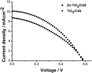
Fig. 2 shows I–V curves of TiO2/CdS and Zn-TiO2/CdS cells. The open circuit potential (Voc), short circuit current (Isc), fill factor (FF) and conversion efficiency (η) of TiO2/CdS and Zn-TiO2/CdS cells are listed in Table 1. It can be observed that the Isc and η have remarkably been enhanced from 8.7 mA cm−2 and 1.92% for the TiO2/CdS cell to 10 mA cm−2 and 2.38% for the Zn-TiO2/CdS cell while FF increases somewhat. According to the explanation by Wang et al.,10 the Isc and η remarkably increases due to the increased band bending resulting from the elevated electron Fermi level, which alleviates the decay of the light-to-electric energy conversion efficiency of cells and enhances charge-collection efficiency.
| Electrode | η (%) | FF | V oc/V | I sc/mA cm−2 |
|---|---|---|---|---|
| Zn-TiO2/CdS | 2.38 | 0.41 | 0.58 | 10 |
| TiO2/CdS | 1.92 | 0.37 | 0.58 | 8.7 |
 | ||
| Fig. 2 I–V curves of TiO2/CdS and Zn-TiO2/CdS cells. | ||
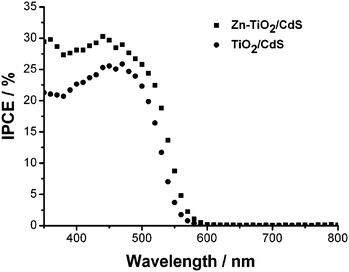
The IPCE is defined as the number of photogenerated charge carriers contributing to the current per incident photon. Fig. 3(a) compares the IPCE spectra of TiO2/CdS and Zn-TiO2/CdS cells. The Zn-TiO2/CdS cell shows a maximum IPCE of 30% at 440 nm, while for the TiO2/CdS cell, the peak only reaches 25%. The Zn doping in TiO2 film contributes to a substantial enhancement of ∼10% at 440 nm in the IPCE.
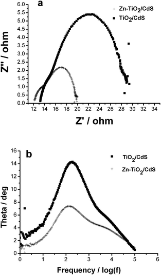
The impedance spectra of TiO2/CdS and Zn-TiO2/CdS cells were studied by applying electrochemical impedance spectroscopy (EIS) under illumination, respectively, as illustrated in Fig. 4(a). Two semicircles, including a small one at high frequency and a large one at low frequency, were observed in the Nyquist plots of EIS spectra. The small semicircle at high frequency corresponds to the charge transfer resistance (Rct) at the interface of the electrolyte/Au counter electrode. A larger arc appearing at low frequency is due to the contribution from electron transport resistance (Rw) in the nanocrystalline TiO2 film. The fitted values of Rct and Rw of TiO2/CdS and Zn-TiO2/CdS cells are shown in Table 2. The Rw of Zn-TiO2/CdS cell is about 7.5 Ω, much lower than the one of TiO2/CdS cell (15.2 Ω), which represents higher electron injection driving force. This result confirms that the Zn doping improves the electron transport in TiO2 film.
| Electrode | R ct/Ω | R w/Ω | τ e/ms |
|---|---|---|---|
| Zn-TiO2/CdS | 5.3 | 7.5 | 1.1 |
| TiO2/CdS | 8.1 | 15.2 | 0.83 |
 | ||
| Fig. 4 (a) Nyquist plots and (b) Bode phase plots of TiO2/CdS and Zn-TiO2/CdS cells. | ||
The frequency peaks can be obtained from Bode phase plots of the cells in Fig. 4(b). According to the EIS model developed by Kern et al.,19 the lifetime (τe) of injected electrons in TiO2 films can be drawn by the positions of the low frequency peak in Fig. 4(b) through the expression: τe = 1/(2πfmax), where fmax is the frequency at the top of the low frequency arc. From Table 2, it can be seen that the Zn-TiO2/CdS cell exhibits higher τe, which is ascribed to higher electron mobility20 which favors the electron transport through a longer distance with less charge trap. Such a high electron mobility in Zn-TiO2 film is due to increased band bending resulting from the elevated electron Fermi level by Zn doping.10 The low electron transport resistance and long electron lifetime could favor the electron transport through a longer distance with less diffusive hindrance to some extent, and thus lead to the reduction of electron recombination and the capture of more effective electrons.21–23 Therefore, the Zn-TiO2/CdS cell exhibits better performance as compared with the TiO2/CdS cell.
Conclusion
A Zn-doped TiO2 film used as a photoanode was synthesized to improve the photovoltaic performance of CdS QDSSCs. The performance of the cells was investigated. The results showed that the η of the Zn-TiO2/CdS cell reached up to 2.38%, which is 24% higher than that of the TiO2/CdS cell. Such an improvement in photovoltaic performance can be ascribed to the reduction of electron recombination and the enhancement of electron transport in TiO2 film by Zn doping.Acknowledgements
This work was supported by the Shanghai Pujiang Program (No. 08PJ14043), Special Project for Nanotechnology of Shanghai (No. 0952nm02200) and Project of Shanghai Normal University (DKL917).Notes and references
- B. O'Regan and M. Grätzel, Nature, 1991, 353, 737 CrossRef CAS.
- Y. L. Lee and Y. S. Lo, Adv. Funct. Mater., 2009, 19, 604 CrossRef.
- W. Li, Y. Wang, H. Lin, S. I. Shaha, C. P. Huang, D. J. Doren, S. A. Rykov, J. G. Chen and M. A. Barteau, Appl. Phys. Lett., 2003, 83, 4143 CrossRef CAS.
- X. Feng, K. Shankar, M. Paulose and C. A. Grimes, Angew. Chem., Int. Ed., 2009, 48, 8095 CrossRef CAS.
- C. Y. Wang, C. Bottcher, D. W. Bahnemann and J. K. Dohrmann, J. Mater. Chem., 2003, 13, 2322 RSC.
- L. Jing, B. Xin, F. Yuan, L. Xue, B. Wang and H. Fu, J. Phys. Chem. B, 2006, 110, 17860 CrossRef CAS.
- K. Das, S. N. Sharma, M. Kumar and S. K. De, J. Phys. Chem. C, 2009, 113, 14783 CrossRef CAS.
- K. H. Ko, Y. C. Lee and Y. J. Jung, J. Colloid Interface Sci., 2005, 283, 482 CrossRef CAS.
- C. Kim, K. S. Kim, H. Y. Kim and Y. S. Han, J. Mater. Chem., 2008, 18, 5809 RSC.
- K. P. Wang and H. S. Teng, Phys. Chem. Chem. Phys., 2009, 11, 9489 RSC.
- T. R. C. K. Wijayarahna, G. M. L. P. Aponsu, Y. P. Y. P. Ariyasinghe, E. V. A. Premalal, G. K. R. Kumara and K. Tennakone, Nanotechnology, 2008, 19, 485703 CrossRef.
- H. Alarcon, M. Hedlund, E. M J. Johansson, H. Rensmo, A. Hagfeldt and G. Boschloo, J. Phys. Chem. C, 2007, 111, 13267 CrossRef CAS.
- C. C. Tsai and H. Teng, Langmuir, 2008, 24, 3434 CrossRef CAS.
- J. N. Nian, S. A. Chen, C. C. Tsai and H. Teng, J. Phys. Chem. B, 2006, 110, 25817 CrossRef CAS.
- D. R. Baker and P. V. Kamat, Adv. Funct. Mater., 2009, 19, 805 CrossRef CAS.
- H. J. Lee, H. C. Leventis, S. J. Moon, P. Chen, S. Ito, S. A. Haque, T. Torres, F. Nuesch, T. Geiger, S. M. Zakeeruddin, M. Grätzel and M. K. Nazeeruddin, Adv. Funct. Mater., 2009, 19, 2735 CrossRef CAS.
- Y. J. Tak, S. J. Hong, J. S. Lee and K. J. Yong, J. Mater. Chem., 2009, 19, 5945 RSC.
- Y. L. Lee and C. H. Chang, J. Power Sources, 2008, 185, 584 CrossRef CAS.
- R. Kern, R. Sastrawan, J. Ferber, R. Stangl and J. Luther, Electrochim. Acta, 2002, 47, 4213 CrossRef CAS.
- J. F. Qian, P. Liu, Y. Xiao, Y. Jiang, Y. L. Cao, X. P. Ai and H. X. Yang, Adv. Mater., 2009, 21, 3663 CrossRef CAS.
- E. S. Kwak, W. Lee, N. G. Park, J. H. Kim and H. Lee, Adv. Funct. Mater., 2009, 19, 1093 CrossRef CAS.
- Q. F. Zhang, C. S. Dandeneau, X. Zhou and G. Cao, Adv. Mater., 2009, 21, 4087 CrossRef CAS.
- C. He, Z. Zheng, H. Tang, L. Zhao and F. Lu, J. Phys. Chem. C, 2009, 113, 10322 CrossRef CAS.
| This journal is © The Royal Society of Chemistry 2010 |

