Nano active materials for lithium-ion batteries
Yonggang Wang
,
Huiqiao Li
,
Ping He
,
Eiji Hosono
and
Haoshen Zhou
*
Energy Technology Research Institute, National Institute of Advanced Industrial Science and Technology (AIST) Umezono, 1-1-1, Tsukuba, 305-8568, Japan. E-mail: hs.zhou@aist.go.jp
First published on 18th May 2010
Abstract
Lithium-ion batteries have been widely used to power portable electronic devices, such as mobile phones, digital cameras, laptops etc., and are considered to be a promising choice of power system for the next generation of electric vehicles, which are central to the reduction of CO2 emissions arising from transport. In order to increase energy and power density to meet the future challenges of energy storage, many efforts have been made to develop nano active materials for lithium-ion batteries. Herein we review the advantages of nano active materials for lithium-ion batteries. Moreover, some disadvantages of nano active materials and their solutions are also discussed.
 Yonggang Wang | Yonggang Wang was born in Xinjiang, China, 1979. He received his BSc and MSc in Chemistry from Xinjiang University. He then obtained his PhD degree in Physical Chemistry from Fudan University in 2007. Currently, he is a post-doctoral fellow of Dr Haoshen Zhou's group at AIST, Japan. His research interests include electrochemical functional materials and their application in lithium-ion batteries, metal-air batteries, supercapacitors and fuel cells. |
 Huiqiao Li | Huiqiao Li was born in Henan, China. She received a BSc degree in Chemistry from Zhengzhou University in 2003, and then received her PhD degree in Physical Chemistry from Fudan University in 2008. Currently, she is a post-doctoral fellow of Dr Haoshen Zhou's group at AIST, Japan. She has authored and co-authored over 10 refereed journal publications. Her research interests include energy storage materials and their application in lithium-ion batteries and supercapacitors. |
 Ping He | Ping He was born in Nanjing, China. He received his BSc and MSc in Applied Chemistry from Nanjing University of Aeronautics and Astronautics. He then obtained his PhD degree in Physical Chemistry from Fudan University in 2009. He is currently a post-doctoral fellow of Dr Haoshen Zhou's group at AIST, Japan. His research interests focus on electrochemical functional materials and energy storage systems. |
 Eiji Hosono | Eiji Hosono studied Chemistry at Keio University, Japan and received his PhD on “Studies on Nanochemical Engineering and Electrical, Optical and Physicochemical Properties of Metal Oxide and Oxyfluoride Materials” in 2004. From 2004 to 2007, he joined Dr Haoshen Zhou's group, at AIST, Japan as a post-doctoral fellow. He was then employed as a researcher in Energy Technology Research Institute, AIST. His current research is the fabrication of advanced functional materials such as lithium-ion batteries, dye-sensitized solar cells, and superhydrophobic films based on the nanostructure control. |
 Haoshen Zhou | Haoshen Zhou was born in Wuxi, China, 1964. He graduated from the Department of Physics, Nanjing University, China, 1985. He obtained his PhD degree from the Department of Chemical Engineering, The University of Tokyo, Japan, 1994. He is now the leader of the Energy Interface Technology Group, Energy Technology Research Institute, National Institute of Advanced Industrial Science and Technology (AIST), Japan. His research interests include the synthesis of nanostructure functional materials and their application in lithium-ion batteries, metal-air batteries, new type batteries/cells, fuel cells, dye sensitized solar cells, hydrophobic/hydrophilic surfaces, electrochemical sensors and optical waveguide gas sensors. |
1. Introduction
One of the greatest challenges at present is how to realize the “low carbon society” based on the advanced technologies for sustainable development. The key technology for this challenge is to develop the next generation of clean energy storage devices with high power density, high energy density and high safety for hybrid electric vehicles (HEV), plug in hybrid electric vehicles (PHEV) and pure electric vehicles (PEV). Recently, a great deal of effort has been spent on nano active materials to develop such clean energy storage devices by improving the performance of lithium-ion batteries,1–5 such as high rate performance and capacitance based on the novel properties as a result of the confining dimension effect. Generally, nano active materials can decrease the diffusion length of lithium ion in the insertion/extraction process which remarkably improves the rate performance of the electrode material. However, there are also some disadvantages to nano active materials, for example, the volumetric density decreases by using nano-sized electrode active materials. Here, the advantages and disadvantages of nano active materials for lithium-ion batteries are summarized. Moreover, some solutions and suggestions for the disadvantages are also addressed. We hope that this review will provide a deeper understanding and promote exciting discussions on the application of nano active materials for lithium-ion batteries.2. Advantages of nano active materials
2.1 Nano-size shortens lithium-ion diffusion length
The high energy density of rechargeable lithium-ion batteries has already led to their dominance in the portable electronic market. However, a new generation of transportation is required combining high energy and power densities for applications such as HEV, PHEV and PEV. To achieve the goal of rechargeable lithium-ion batteries for new markets, lithium-ion intercalation electrode materials need to possess excellent rate capability which is associated with the electronic conduction and the diffusion of lithium-ion during the insertion/extraction process of intercalation compounds.1Fig. 1 shows a representative sketch of the charge transfer process which occurs within intercalation compound particles. For the discharge process the following process is involved: the solvated lithium-ion diffuses from the bulk electrolyte solution, then a charge-transfer reaction occurs in the intercalation compound/electrolyte interface accompanied by accepting certain electrons, afterwards lithium-ion diffuses into the bulk host material particle. Consequently, the charge-transfer at the interface mainly involves lithium-ion diffusion and electronic conduction, which are two coinstantaneous processes.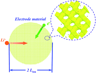 | ||
| Fig. 1 Representative sketch of a charge transfer process that occurs within an intercalation compound particle (take spinel Li4Ti5O12 as an example). | ||
Improvement of the electronic conduction of electrode materials will be discussed later. The lithium-ion diffusion in host electrode materials is associated with the lithium-ion diffusion coefficient and the diffusion length. The characteristic time for diffusion can be represented as follows:
| τ = Lion2/DLi | (1) |
| Intercalation materials | D Li/cm2 s−1 | Average voltage/V | Theoretic capacity/mAh g−1 |
|---|---|---|---|
| LiMn2O46 | 10−10 – 10−7 | 4.1 | 148 |
| LiCoO27 | 10−11–10−10 | 3.7 | 140 |
| LiCo0.33Mn0.33Ni0.33O28 | 10−10–10−9 | 3.8 | 200 |
| LiFePO49 | 10−14–10−11 | 3.5 | 170 |
| LiV3O810 | 10−9–10−8 | 3.0 | 280 |
| LiTi2(PO4)311 | 10−7–10−5 | 2.5 | 138 |
| Li4Ti5O1212 | 10−17–10−14 | 1.5 | 175 |
| Cu6Sn513 | 10−10–10−12 | 0.2 | 584 |
| Graphite14 | 10−11–10−9 | 0.1 | 370 |
Nano-sized materials can provide short diffusion lengths for lithium-ion. In contrast, commercial batteries are mostly based on micrometre-sized electrode materials, i.e. powders containing particles in the micrometre range and having a low surface area (<10 m2 g−1). From the point of view of lithium-ion diffusion, these micrometre-sized electrode materials are not beneficial for high-rate charge/discharge because of their long diffusion lengths for lithium-ion. In the practical process of lithium-ion diffusion, the effective specific capacity will depend on the volume ratio η,15
 | (2) |
The strategy that enhances the rate capability with nano-sized particles was successfully applied in most electrode materials, e.g., LiFePO4,17,18 Li0.33MnO2,19 Li0.44MnO2,20 LiCoO2,21 LiMn2O4,22–24 LiNi0.5Mn1.5O4,25 Li4Ti5O12.26,27 Combining the advantage of low cost, low toxicity, and the ability to be fabricated as a nanomaterial delivering fast lithium-ion intercalation, much attention has recently focused on titanium oxides.26,28,29 We reported a simple chemical lithiation and post-annealing process to synthesize nanocrystalline Li4Ti5O12 anode material.26 The as-synthesized Li4Ti5O12 powders showed an average grain size of about 30 nm with high phase purity and crystalline (Fig. 2). The discharge capacity of this electrode material is 149 mAh g−1 at 0.035 A g−1. On increasing the current density, the plateau on the discharge curves is maintained, even up to a high current density of 3 A g−1, although an overpotential is observed. The capacities at 1 and 3 A g−1 are 80% and 57% of that at 0.035 A g−1, respectively, indicating quite good capacity retention at high current rates (Fig. 3).
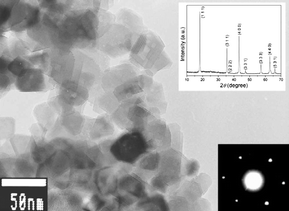 | ||
| Fig. 2 TEM image of the nano-sized Li4Ti5O12 obtained by annealing the intermediate Li–Ti–O precursor at 700 °C for 5 h. The inset shows the XRD and SAED patterns of this powder (ref. 26). | ||
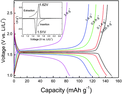 | ||
| Fig. 3 Discharge and charge profiles at different current densities for the Li4Ti5O12 electrode made from powders annealed at 700 °C for 5 h. The inset shows a CV curve recorded at a scan rate of 0.1 mV s−1 (ref. 26). | ||
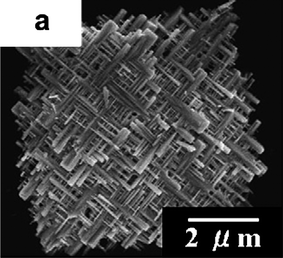
Recently we also designed a strategic synthesis process to synthesize novel single crystalline spinel LiMn2O4 nanowires without any bundle-like structure based on a novel reaction method using Na0.44MnO2 nanowires as a self-template (Fig. 4).23 This prepared spinel LiMn2O4 is a single crystalline nanowire with a high aspect ratio of about 100 and diameter of around 50–100 nm.
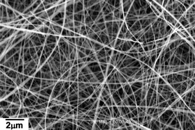 | ||
| Fig. 4 SEM images of the synthesized single crystalline spinel LiMn2O4 nanowires (ref. 23). | ||
As shown in Fig. 5, the LiMn2O4 single crystalline nanowire exhibits 118, 108, 102, and 88 mAh g−1 at rates of 0.1, 5, 10, and 20 A g−1 respectively. It indicates that above 90%, 85%, and 75% capacity at 0.1 A g−1 can be retained even at remarkable high charge-discharge rates of 5, 10, and 20 A g−1, respectively. The specific capacity at a constant current density of 5 A g−1 seems to be the best high rate charge–discharge result for spinel LiMn2O4. These large capacities at high rates come from the nanowires morphology and the high quality of the single crystal, which decrease the lithium-ion diffusion length and improve electronic transport. Besides the nanowires structure, nanoparticles of LiMn2O4 directly synthesized by one-step hydrothermal reaction also can exhibit the especially excellent high rate capability.24
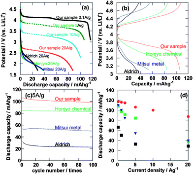 | ||
| Fig. 5 (a) The discharge curves of the single crystalline spinel LiMn2O4 nanowires and commercial LiMn2O4. (b) The charge–discharge curves at the second cycle at a high rate of 5 A g−1. (c) Cycle performance at a high rate of 5 A g−1. (d) The relationship between discharge capacity and current density of the single crystalline spinel LiMn2O4 nanowires at the second cycle (ref. 23). | ||
2.2 Nano-size combining with electronic conductive coating improves electronic transport
As mentioned in section 2.1, lithium-ion intercalation/de-intercalation of electrode active materials is coupled with electronic transport within the electrode. However, most electrode active materials, especially cathode materials (such as LiMn2O4 or LiFePO4), are semiconductor or even insulator. The resistance, arising from the inherent low electronic conductivity of active materials and the boundary interfaces among active material particles, would much limit the high power performance of lithium-ion batteries. Accordingly, besides lithium-ion diffusion in the crystal framework of electrode active materials, electronic transport within the electrode also limits the power performance of lithium-ion batteries. Theoretically, nano-size electrode active material can also shorten the path length for electronic transport, and thus alleviate the limitation of low electronic conductivity.1 However, in practical application, “nano-size” only cannot effectively shorten the path length for electronic transport. The electronic transport in a nanomaterial based electrode is shown schematically in Fig. 6, where some carbon additive is employed to improve the conductivity of total electrode. Since nano-sized particles have a very high specific surface area and high surface energy, and tend to form agglomerates, they are difficult to disperse and are mixed with a carton additive (see Fig. 6).3 Accordingly, the electronic transport length (Le) is still much higher than the particle size (r) because only a small amount of nanoparticles can directly contact the carbon additive and obtain electrons (see the inset of Fig. 6). Furthermore, the large interface resistance still exists, especially when the particle size is within a typical nano-scale.3 If each nanoparticle is fully coated with an electronic conductive layer, the electronic transport length (Le) in an electrode would be effectively shortened. In this case, the electronic transport length (Le) across the active material is equal to (or less than) the particle-size (r) of the nanomaterials (as shown in Fig. 7). This is because electrons can completely pass along the out surface of each nanoparticle. With a thin electronic conductive coating layer, nano-size can effectively reduce the electronic transport length (Le) across the active material. Furthermore, the electronic conductive coating layer can reduce the interface resistance.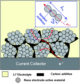 | ||
| Fig. 6 Schematic representation showing the electronic transport length (Le) in nanoparticles based electrode. | ||
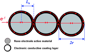 | ||
| Fig. 7 Schematic illustration of the electronic transport length for nanoparticles with full conductive coating. | ||
As mentioned above, “nano-size” combining with “electronic conductive coating layer” should be an ideal method to improve the electronic transport in the electrode. For example, Guo et al. have successfully prepared a TiO2/RuO2 nanocomposite in which TiO2 nanoparticles are coated by the electronic conductive layer of RuO2.30 In their report, the prepared TiO2/RuO2 nanocomposite shows superior high rate when used as anode material for lithium-ion batteries. Furthermore, they successfully extended this concept to LiFePO4.31 Similarly, the LiFePO4/RuO2 nanocomposite also displays high power (or rate) performance.31 However, RuO2 is still very expensive. Carbon coating is the widely used conductive coating technique for electrode active materials.18,32–44 Herein, we take the previous study about LiFePO4 as a typical example to further demonstrate the advantage of “nano-size” combining with “electronic conductive coating”.
Olivine (LiFePO4) is considered to be one of the most promising cathode materials for the next generation of lithium-ion batteries due to its low toxicity, low cost, and high safety.45,46 However, these positive aspects are counteracted by the low electronic conductivity of the material (about 10−9 to 10−10 S cm−1).47 As mentioned in Fig. 7, “nano-size” combined with “electronic conductive coating” should be one of the ideal structures for LiFePO4 to alleviate the limitation of low electronic conductivity. Approaches based on the thermal decomposition of carbon-containing precursors have been widely studied for the preparation of carbon-coated LiFePO4 particles.48–55 Recently, we reported an in situ polymerization restriction method for the synthesis of a LiFePO4/carbon composite formed from a highly crystalline LiFePO4 core with a size of about 20–40 nm and a semi-graphitic carbon shell with a thickness of about 1–2 nm (see Fig. 8(a) and (b)).18 As shown in Fig. 8(c), the full coating of carbon layer ensures that electrons pass along the out surface of each LiFePO4 particle, which effectively shortens the path length for electronic transport and reduces the interface resistance. Furthermore, lithium ions can easily intercalate into the framework of LiFePO4 through the partly graphitic carbon coating layer with a thickness of 1–2 nm. Certainly, such typical nano-size LiFePO4 particles also shortens the lithium-ion diffusion path (“nano-size shortens lithium-ion diffusion path” has been discussed in section 2.1 in detail).
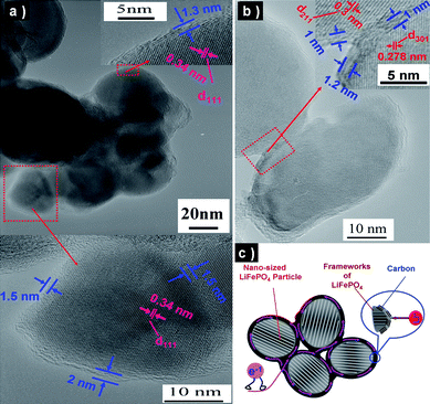 | ||
| Fig. 8 (a, b) TEM images of LiFePO4 nanoparticles with full coating of carbon layer. (c) Schematic illustration summarizing the characters of LiFePO4/carbon composite (ref. 18). | ||
Owing to these characters mentioned in Fig. 8(c), our prepared LiFePO4/carbon composite displays very high rate performance. As shown in Fig. 9, the discharge capacity of the prepared composite is 168 mAh g−1 at a current density of 0.1 A g−1 (rate of about 0.6 C), and it still delivers a capacity of 90 mAh g−1 even at the current density of 10 A g−1 (rate of about 60 C; discharge/charge of all the LiFePO4 within 1 min!). Inspired by this finding, we also successfully prepared nano-sized Li4Ti5O12 particles completely coated with a thin nano-carbon layer (see Fig. 10(a)).27 Electrochemical tests indicate that our prepared Li4Ti5O12/carbon composite also displays high rate performance (see Fig. 10(b)).
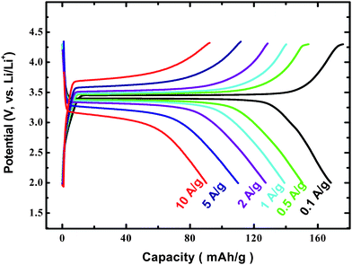 | ||
| Fig. 9 Charge–discharge curves of LiFePO4/carbon composite with different current densities (ref. 18). | ||
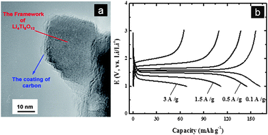 | ||
| Fig. 10 (a) TEM image of Li4Ti5O12 nano-particle with carbon coating. (b) Charge–discharge curves of Li4Ti5O12/carbon composite (ref. 27). | ||
2.3 Nano-size enhances the electrode capability of Li storage
Among the various size effects that have been found in the materials used in lithium-ion batteries, the most attractive one might be the remarkably enhanced capability of Li storage when from “micro” to “nano”, which behaves in the form of:(i) Initiating new lithium storage mechanisms, known as a “conversion” mechanism mainly refers to reversible in situ formation and decomposition of LiyX (where X = O, S, F, or N) accompanying the reduction and oxidation of metal nanoparticles. The overall mechanism is described by the following equation:
 | (3) |
(ii) Promoting electrode activity, as it has been found that inactive materials for Li storage become active when “going nano”. Those compounds that account for quite low lithium-ion diffusion coefficients show the representative cases, for example, rutile TiO2. Lithium-ion diffusion in rutile TiO2 is highly anisotropic: a large distortion of the rutile framework makes lithium-ion diffusion in the a–b planes very slow at low temperature (DLi ∼10−15 cm2 s−1), which prevents lithium ions from reaching thermodynamically favorable octahedral sites residing in the a–b planes and separates Li ions in the c channels. Hence, only a negligible amount of lithium ions can be stored in the bulk form of rutile TiO2.61,62 However, at the nanoscale the situation is significantly different. Seen in Fig. 11(a), the rutile TiO2 nanoparticle with an average size of 15 nm can enable a full loading of lithium (x > 1 in LixTiO2) in the first discharge process. And it delivers a surprisingly high reversible capacity of 263 mAh g−1; while in contrast, rutile TiO2 with an average size of 300 nm only delivers a much lower reversible capacity (50 mAh g−1) at the same current density, clearly showing a strong dependence of the electrochemical activity on particle sizes.63 About 0.7 Li per rutile TiO2 can be reversibly loaded and unloaded in subsequent cycling (Fig. 11(b)). It is believed that the limits to lithium-ion diffusion in the a–b planes have been weakened because of the very short diffusion length within the nano-sized rutile TiO2 electrode. That is, more octahedral sites in the a–b planes can be reached by lithium ions within a certain time. Similar results have also been reported by Hu et al. that rutile TiO2 of 10 nm × 40 nm in size can reversibly accommodate Li up to 168 mAh g−1 at 1–3 V vs. Li/Li+ with excellent capacity retention on cycling.64
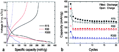 | ||
| Fig. 11 The initial potential-capacity profiles (a) and cycle performances (b) of rutile TiO2 with different particle sizes cycled at 0.05 A g−1. The average particle size is 15 nm, 30 nm, and 300 nm for R15, R30 and R300, respectively (ref. 63). | ||
(iii) Increasing surface/interface storage. This results from the short diffusion length and high contact area between the active materials and electrolyte. The overall capacity of Li storage is critically dependent on the accessible sites in the host material for the guest specie “lithium ion” within the given time. Compared to the bulk sites, surface sites or near-surface sites are of higher activity since they are undoubtedly easier to be accessed by lithium ions. As had been concluded in the case of nano-sized rutile TiO2,65 the amount of surface-stored lithium significantly increased with decreased particle size, which contributed substantially to the total lithium storage capacity, in addition to the enhanced bulk Li storage by shortened lithium-ion transport length (as discussed above). The capacity contributed by surface Li storage was very stable upon cycling or various current rates, which means large surface is also beneficial to high rate performances of an electrode material. Nano-structured VxOy materials with ultra-high surface areas have also been reported with much enhanced capacity. As reported by Tarascon et al.,66 nanofiber-like V2O5 aerogels with a surface area higher than 100 m2 g−1 can exhibit a large capacity near 400 mAh g−1 and allow high rates of discharge. Their derivative nanotextured VO2 (B) aerogels even delivered a higher capacity over 500 mAh g−1,67 the highest value of those ever reported for vanadium oxides. In view of the large surface area of this nanotextured VO2 (B) (185 m2 g−1), it is reasonable to assume that the surface/near surface storage might play an important role in such a large capacity. Other 1D nanostructures such as nanowires,68,69 nanorods,70,71 and nanobelts72 have been well documented for vanadium-based cathode materials.
Compared to 1D nanostructures, 3D nano/micro hierarchical structures are more attractive since they can combine both the advantages of nano and micro. The nanometre-sized building blocks of the hierarchical structure can provide short lithium-ion diffusion lengths, additional surface storage and possible new Li storage mechanisms, thus are favorable for electrode kinetics and high capacities; while the micro-assemblies guarantee good stability and ease of fabrication.3 Recently, we developed a nanothron VO2(B) hollow microsphere by a facile one-step hydrothermal method.73 As shown in Fig. 12, the hollow microspheres about 1 μm in diameter were self-assembled by well-defined VO2(B) nanothorn single-crystals (10 nm in width and several tens nanometres in length) growing perpendicularly onto the sphere surface. When used as the cathode material for a lithium-ion battery, this VO2(B) material can provide inner and outer wall surface of contact sites between electrode material and electrolyte, porous tunnels for electrolyte penetrating, short lithium diffusion length within the tiny nanothrons, and a 3D rigid structure to prevent the nanothrons from agglomeration. A large discharge capacity of 450 mAh g−1 can be obtained at the current density of 10 mA g−1. Similarly, improved Li storage properties have also been found by Cao et al. for V2O5 by fabricating hollow microspheres with uniform hedgehog-like morphology.74
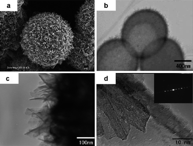 | ||
| Fig. 12 Panoramic SEM graph (a) and TEM graph (b) of the synthesized nanothorn VO2(B) hollow microspheres by hydrothermal method; details of the hollow sphere surface (c) and individual nanothron building block (d) by TEM at high magnitude (ref. 73). | ||
2.4 Ordered mesoporous structure favors both Li storage and fast electrode kinetics
An optimized nano-structure for electrode materials with both high capacity and high power is shown to be an ordered mesoporous structure. Such mesoporous materials are composed of micrometre-sized particles within which highly ordered mesopore (2–50 nm) arrays exist throughout the whole particle and ultrathin pore walls made of nano-sized solids interconnect surrounding the pores to form 3D continuous frameworks. The ordered mesoporous structure possesses several unique advantages for Li storage75–87: (i) the highly porosity results in a large surface area and good penetration of electrolyte into the deep inner of the electrode, giving rise to a large contact area between solid and electrolyte; (ii) the pores in meso-size are wide enough for the wetting of non-aqueous electrolyte containing large organic molecules, ensuring a high flux of lithium across the interface; (iii) the ordered throughout pore arrays provide fast and versatile transport pathways for the electrolyte ions, which is critically important in the case of high rate charge/discharge; (iv) the ultrathin pore walls are only 2–8 nm across the wall thickness, rendering a very short transport length for lithium ions during insertion/extraction, hence, equal high rates throughout the material; and (v) the rigid 3D framework might help the structure remain standing against agglomeration and degradation, and the high porosity in it might also provide free space to accommodate the volume change upon lithium-ion insertion/extraction, therefore, promising a better cycle performance during long term charge/discharge. We would like to further explain the advantages of ordered mesoporous structure based on the following mentioned studies.As mentioned in section 2.3, the particle size and surface area have profound effects on the lithium storage performances of TiO2. When further towards the morphology from nanoparticle to ordered mesoporous structure, the resulting higher surface area, smaller nanocrystal size, and better diffusion pathway leads to enhancement of the electrode capacity, power performance and cycle life to an impressive degree. For example, a series of TiO2-based materials with a novel self-ordered, crystalline-glass, mesoporous nanocomposite (GCMN) structure were developed by our group for lithium-ion batteries. The so-called GCMN materials, for which the composition can be described as TiO2–P2O5–MxOy (where M refers to metal element), were synthesized by a surfactant-templated self-assembly method followed with the controlled in situ crystallization of the precursor materials.75 In GCMN, the functional nanocrystals with electrochemical activity were used as the building blocks of ordered mesopores, and the semiconductive glass (P2O5) phase can act both as the “glue” between nanocrystals and as a multi-functionalized component in the composites. The electrochemical results show that the reversible capacity of TiO2–P2O5 GCMN at low current density was as high as 350 mAh g−1, and the specific capacities (energy density) at high current densities (power density) can be improved several hundred folds when the CGMN replaced TiO2 powder as the electrode material for lithium storage.15 As shown in Fig. 13(a), the 4 nm uniform mesochannels of CGMN can be filled with electrolyte solution during use to provide electrolyte and lithium-ion pathways throughout the material. The metal-oxide framework is assembled by 3–5 nm TiO2 anatase nanocrystals, in which case the required diffusion length for lithium-ion could be reduced to half of the frame-wall thickness (about 2 nm as shown by Fig. 13(b)). This arrangement guarantees the charge–discharge process would be complete in a very short period of time, thus resulting in a high specific capacity, e.g. 390 mAh g−1 at 0.1 A g−1, 260 mAh g−1 even at a current as high as 10 A g−1 (Fig. 13(c)), while the purchased TiO2 powder (TiO2 PP) and ordinary mesoporous TiO2 powder (TiO2-MP) exhibits much lower capacity according to the CV results in Fig. 13(d). The high current (10 A g−1) can be remarkably reduced to an actual low density value in terms of per m2 due to the high surface area (about 280 m2 g−1) of CGMN TiO2, so the obtained specific capacity can remain very high. On the other hand, such a good power performance may profit from the presence of P2O5-glass phase which is known to have good ionic conductivity. Recently, super high rates of charge and discharge has also been achieved for LiFePO4 through a surface coating of pyrophosphaste.76 The P2O5-glass phase in the CGMN TiO2 can form a buffer layer between active nanocrystalline TiO2 blocks to relax the structure stress during insertion and extraction of lithium ions, thereby it showed a very good cycle performance, e.g., a capacity of 195 mAh g−1 up to 200 cycles and 150 mAh g−1 up to 800 cycles can be remained with a high coulomb efficiency of 96%. Furthermore, the P2O5-glass phase can act as a host for electronic conductive oxide dopants to build up an ideal electronic path throughout the material and to add lithium ions as a network modifier during the first insertion process to form an ionic path, so the doped TiO2 CGMNs such as TiO2–P2O5–SnO2 and TiO2–P2O5–CuO also demonstrate very good performances for lithium storage including both high capacity and high power. The unique characteristics of GCMN materials—uniform nanochannels, uniform nanoframework, high surface area, glass-phase buffer layer, and electronic/ionic network path—suggest their suitability for the development of high power and high energy density lithium-ion batteries.
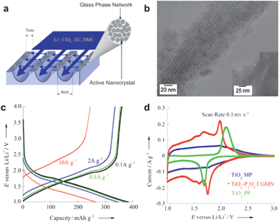 | ||
| Fig. 13 (a) A schematic representation of the effective diffusion length in GCMN materials. (b) TEM image and high-resolution TEM images of the TiO2–P2O5 GCMN along. (c) Charge/discharge curves of TiO2–P2O5 GCMN at different current densities. (d) CV curves of TiO2–P2O5 GCMN, commercial anatase TiO2 (PP), ordinary mesoprous TiO2 (MP) (ref. 15). | ||
Although the ordered mesoporous structure can provide a much reduced diffusion length for Li ions, it seems little helpful for the electronic conduction due to the micrometre-sized particle. As shown in Fig. 14(a), the lithium-ion diffusion length (Lion) for a mesoporous particle is only about several nanometres (half the thickness of the pore wall) while the electron conduction length (Le) for the particle is still in micrometre scale, similar to the case of conventional powder electrode materials. So, we further developed a nanotube structure with ordered mesoporous tube walls.77 The synthesized TiO2 nanotubes have multi-model porosity: macropores in the hollow tubes (Fig. 14(b)) inherited from the alumina membrane template and mesopores in the tube walls derived of soft surfactants (Fig. 14(c)). Such a structure not only gives rise to a large surface area (about 400 m2 g−1) thus equal to a high contact area of electrolyte/electrode, but also provides fast transportation for both lithium ions and electrons through the network (Fig. 14(a)). Therefore, the hierarchical TiO2 nanotubes can demonstrate ultrahigh rate performances, for example, 150 mAh g−1 is still obtained even at a current density of 40 A g−1 (about 240 C), and its capacity reaches 289 mAh g−1 at 1 A g−1 (corresponding to x = 0.86 for LixTiO2), much larger than that (x = 0.5) reported for ordinary anatase TiO2. Besides mesoporous TiO2 mentioned above, our group also developed an ordered mesoporous carbon and applied it in lithium-ion batteries as an anode material. The ordered mesoporous carbon (denoted as CMK-3) with a specific surface area of 1030 m2 g−1, obtained by carbonation of sucrose inside the pores of the mesoporous silica template, can deliver a high reversible specific capacity of 1100 mAh g−1 (Li3C6) for lithium storage. After the first cycle, the discharge and charge still remained at a high capacity level (LixC6, x = 2.3 to 3.0) with a good cycle performance.78 Currently, ordered mesoporous carbons have attracted much attention in the research fields of both lithium-ion batteries and supercapacitors.79–81 Attributed to the good conductivity of mesoporous carbon, it can also act well as a multifunctional support in composite electrode material, such as the carbon–sulfur cathode reported recently.82
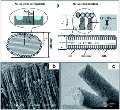 | ||
| Fig. 14 (a) Schematic paths of lithium-ions (Lion) and electrons (Le) for the mesoporous TiO2 microparticle and nanotube, respectively. (b) SEM of TiO2 nanotube arrays prepared by a supercritical CO2 drying process with AAO membranes as the template. (c) TEM image of individual nanotubes with ordered mesoporous wall structure (ref. 77). | ||
Besides anode materials, many efforts have also been made on ordered mesoporous cathodes in the past several years. β-MnO2, which was originally considered as being unable to store Li due to the poor kinetics of lithium intercalation/de-intercalation limited by its narrowest [1 × 1] channels among all the manganese dioxides (α, β, γ phases), became active to Li storage when towards an ordered mesoporous structure.83,84 Later, ordered mesoporous LiMn2O4 was further synthesized by using mesoporous MnO2 as the manganese precursor.85,86 As a bulk phase, LiMn2O4 possesses the best rate performance of any positive electrode, while the mesoporous form of LiMn2O4 exhibits even better rate capability, with a higher capacity to store charge at high rates than the bulk phase. Ordered mesoporous LiCoO2 was also reported by Bruce et al. with superior cycling during continuous lithium insertion/extraction when compared to low-temperature bulk LiCoO2.87 The authors attributed the superior performances of mesoporous LiCoO2 to its better particle contact of the micrometre-sized particles, better electrolyte access via the ordered pore structure, and the short diffusion distances for lithium ions and electrons within the walls.
All of the above results show us ordered mesoporous forms of electrode materials possessing remarkably improved properties for lithium storage, both in capacity and in high power performance. More significant compounds for lithium-ion batteries with ordered mesoporous structures are expected to come true in the future.
2.5 Nano-structure enhance cycle stability
Besides their excellent advantages based on the nano active materials presented above, the nanometre-sized electrode materials may also exhibit good cycle stability. The capacity fading of lithium-ion batteries upon cycling is usually caused by the large volume expansion/contraction associated with Li insertion/extraction or Li alloying/de-alloying, which inevitably introduces cracking or crumbling of the anode material and thus causes loss in capacity during cycling.88 For example, Si is an attractive anode material for lithium batteries because it has a low discharge potential and the highest known theoretical charge capacity (4200 mAh g−1). Although this is more than ten times higher than existing graphite anodes and much larger than various nitride and oxide materials,89 Si anodes have limited applications because volume changes by 400% upon insertion and extraction of lithium-ion, results in pulverization and capacity fading.90 Fortunately, nano-structured electrode materials can absorb this large volume expansion/contraction, preserving the integrity of the electrode and leading to stable cycle performance. Based on this strategy, Si nanowire battery electrodes were prepared to circumvent these issues as they can accommodate large strain without pulverization, provide good electronic contact and conduction, and also display short lithium diffusion length. It presents a discharge capacity close to 75% of the theoretical capacity and with little fading during cycling.91Similarly, tin oxides, such as SnO and SnO2, are attractive materials as potential anodes because of their high theoretical capacities (SnO2: 783 mAh g−1, SnO: 875 mAh g−1). The high specific capacities of tin oxides as an anode material have been attributed to the formation of the Li4.4Sn alloy. However, their commercial applications are hampered by poor cycle ability that are caused by the mechanical damage of the electrodes due to large expansion rate of 300% with alloying during the lithium-ion insertion process. Recently a smart SnO meshed plate nanostructure consisting of nano-sized ribbons was proposed as an anode material for lithium-ion rechargeable batteries (Fig. 15).92 This prepared SnO meshed plate exhibits a good cycle performance and presents the reversible capacity of 320 mAh g−1 after 20 cycles, which was higher than that of flat plates (250 mAh g−1). It suggests that the mechanical damage of the meshed electrodes during the lithium-ion insertion/extraction could be suppressed because the specific skeletal framework consisting of nanoribbons provides sufficient space to buffer the volume expansion (Fig. 16). Thereby, the nano-structured meshed framework improves the cycle performance of tin oxide electrodes. We also reported the synthesis of nanoporous metal tin as an anodic electrode for high rate lithium-ion secondary batteries with a flat plateau and good cycle stability.93 The small volume change based on the Sn → Li7/3Sn reaction results in its good cycle performance. Furthermore, the nanostructured composite materials including an active–inactive component plays the role of buffer to accommodate large strain without pulverization, which achieves the satisfied effect to enhance the cycle stability.94 For example, Sn nano-sized particles dispersed in inactive carbon matrix can effectively alleviate the electrode strain and lead to the improved cycle stability.30
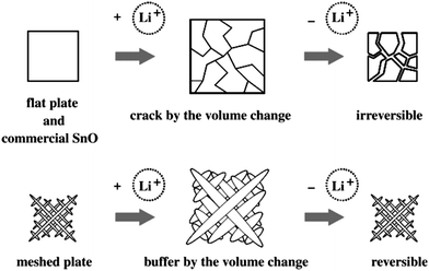 | ||
| Fig. 16 Schematic illustrations of Li+ insertion/extraction of meshed plate, flat plate and commercial SnO (ref. 92). | ||
3. Disadvantages of nano active materials
3.1 Low density
Owing to their large surface area and porous structure, nanomaterials usually exhibit lower density when compared with micromaterials. Accordingly, the pack density of nanomaterial-based electrodes is generally lower than that of micromaterial-based electrodes, which limits the volumetric energy density of lithium-ion batteries. In fact, volumetric energy density of lithium-ion batteries is quite important for their applications, especially for the application in EV.3.2 High surface reactions
The high surface area and high surface energy of nanomaterials also increases undesirable surface reactions. When stored as the raw material of lithium-ion batteries, some nanomaterials exhibit poor stability in air atmosphere. Herein, olivine LiFePO4 is a case in point because Fe2+ is quite unstable in air atmosphere where O2 and a small amount of H2O co-exist. A recent study has demonstrated that the stability of LiFePO4 in air atmosphere decreases with the reduction of particle-size since nano-size increases the exposure area in air.95 This may also limit (or affect) the large-scale application of nano-sized LiFePO4. When nanomaterials are used as the cathode in practical lithium-ion batteries, their high surface area increases the risk of side reactions between electrode and electrolyte, which results in a high irreversibility and poor cycle life. Furthermore, thick solid electrolyte interphase (SEI) films generally form on the surface of nano-sized anodes, which consume lots of the lithium ions supplied by cathodes.33.3 Complicated synthesis route
Currently, the dominant synthesis method for electrode materials (especially for cathode materials) of lithium-ion batteries is still a solid-state reaction which can be summarized as the heat-treatment of precursor materials. For instance, spinel LiMn2O4 can be prepared by directly calcining the suitable Li- and Mn-containing precursors. The synthesis route of the solid-state reaction is simple, and can be easily extended to industrial production. However lots of synthesis routes for nanomaterials, such as hard-template method and hydrothermal synthesis, are more complex when compared with the solid-state reaction. Accordingly, to develop, a facile synthesis route should be very important for the practical application of nanomaterials, especially, if the age of EVs really comes, large-scale industrial production of electrode materials would be inevitable.4. Suggestion of some solutions for the disadvantages of nano active materials
4.1 Nano/nano mixed or nano/micro mixed electrode materials
As mentioned in section 3.1, the low pack density is one of the drawbacks of nano active materials, which limits the total volumetric energy density of lithium-ion batteries. In our opinion, to mix nanomaterials of different morphologies should be an effective method to improve the density of the electrode (here, we call it nano/nano mixed electrode materials). As mentioned in section 2.1, we have successfully synthesized LiMn2O4 nanowires and LiMn2O4 nanoparticles (see Fig. 17 (a) and (b)).23,24 If the LiMn2O4 nanowires and nanoparticles are mixed with a special ratio, improved pack density of the electrode would be achieved because nanoparticles can be dispersed in the network structure of nanowires (see Fig. 17(c)). In addition, the network structure arising from nanowires can provide a uniform path for electronic transport. To mix nano-sized materials with micro-sized materials should be another effective way to increase the pack density of the electrode, in respect that nano-sized particles can effectively occupy the interspaces among micro-sized particles.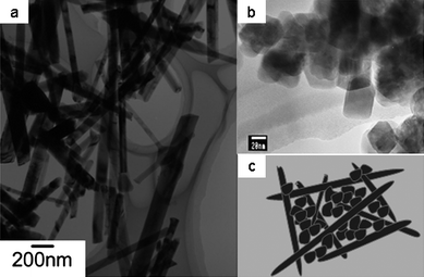 | ||
| Fig. 17 TEM images of (a) LiMn2O4 nanowires reported in ref. 23 and (b) LiMn2O4 nanoparticles reported in ref. 24. (c) Schematic illustration of nanowires/nanoparticles mixed electrode. | ||
4.2 Surface coating
Surface coating should be a promising way to alleviate the undesirable surface reaction arising form the large surface area of nanomaterials. In section 2.2 (Fig. 8), we have discussed that full carbon coating combined with nano-size can effectively improve the electronic transport for LiFePO4. In addition, the full coating of carbon can also improve the stability of LiFePO4 in air atmosphere. As shown in the left side of Fig. 18, the carbon coating layer can prevent the direct contact between the LiFePO4 nanoparticles and air. Accordingly, when stored as a raw electrode-material in air atmosphere, our prepared LiFePO4/carbon nanocomposite (reported in ref. 18) would display high stability (at present, this work is sill in progress). When applied in a practical lithium-ion battery, the carbon coating layer permits the pass of lithium ions (see Fig. 18, right side). However, these solvent molecules in electrolyte can not pass across the carbon coating layer, which avoids the direct contact between LiFePO4 nanoparticles and electrolyte. Thereby, the prepared LiFePO4/carbon composite exhibits an excellent cycling performance, with less than 5% discharge capacity loss over 1100 cycles.18 Furthermore, surface coating with oxides such as ZnO and A12O3 can also reduce the contact area between cathode materials and electrolyte and suppress phase transitions.96–98 For example, ZnO coating has been used to enhance cycle performance of LiMn2O4 and LiNi0.5Mn1.5O4.97,98 On the other hand, the carbon coating layers also lead to stabilized SEI films especially on anodes, which improves cycling performance.3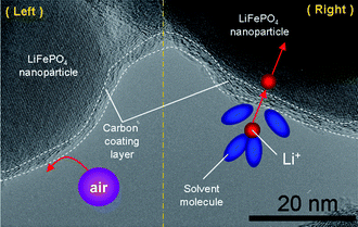 | ||
| Fig. 18 High resolution TEM image of LiFePO4/carbon nanocomposite. Left: schematic representation showing that a carbon coating layer can prevent the direct contact between LiFePO4 nanoparticles and the air including O2 and H2O. Right: schematic representation showing that a carbon coating layer can reduce the contact area between LiFePO4 nanoparticles and solvent molecules in electrolyte (ref. 18). | ||
5. Conclusion
In this review, we simply introduced the advantages of nanomaterials for application in lithium-ion batteries based on different examples. It is undoubted that nano-materials will play a more and more important role in future research of lithium-ion batteries. To first analyse the inherent drawback of an electrode material, then design a special nano-size or nano-structure to alleviate this drawback, and finally prepare the designed material should be one of the most promising ways to improve the performance of lithium-ion batteries. However, it should be noted that nano active materials also have their disadvantages such as low density, high surface reaction and complicated synthesis route. Accordingly, when we design and prepare nano active materials for lithium-ion batteries, a balance between advantages and disadvantages for the practical application of nano active materials in lithium-ion batteries should be carefully considered.6. Reference
- A. S. Aricò, P. G. Bruce, B. Scrosati, J.-M. Tarascon and W. Van Schalkwijc, Nat. Mater., 2005, 4, 366 CrossRef CAS.
- J. Chen and F. G. Cheng, Acc. Chem. Res., 2009, 42, 713 CrossRef CAS.
- Y. G. Guo, J. S. Hu and L. J. Wan, Adv. Mater., 2008, 20, 2878 CrossRef CAS.
- H. Li, Z. X. Wang, L. Q. Chen and X. J. Huang, Adv. Mater., 2009, 21, 4593 CrossRef CAS.
- J.-M. Tarascon and M. Armand, Nature, 2001, 414, 359 CrossRef CAS.
- D. Guyomard and J. M. Tarascon, J. Electrochem. Soc., 1992, 139, 937 CAS.
- D. Aurbach, M. D. Levi, E. Levi, H. Teller, B. Markovsky, G. Salitra, U. Heider and L. Heider, J. Electrochem. Soc., 1998, 145, 3024 CAS.
- Y. Idemoto and T. Matsui, Solid State Ionics, 2008, 179, 625 CrossRef CAS.
- P. He, X. Zhang, Y. G. Wang, L. Cheng and Y. Y. Xia, J. Electrochem. Soc., 2008, 155, A144 CrossRef CAS.
- G. J. Wang, Q. T. Qu, B. Wang, Y. Shi, S. Tian, Y. P. Wu and R. Holze, J. Power Sources, 2009, 189, 503 CrossRef CAS.
- G. X. Wang, D. H. Bradhurst, S. X. Dou and H. K. Liu, J. Power Sources, 2003, 124, 231 CrossRef CAS.
- L. Kavan, J. Prochazka, T. M. Spitler, M. Kalbac, M. T. Zukalova, T. Drezen and M. Gratzel, J. Electrochem. Soc., 2003, 150, A1000 CrossRef CAS.
- J. J. Zhang, P. He and Y. Y. Xia, J. Electroanal. Chem., 2008, 624, 161 CrossRef CAS.
- S. S. Zhang, K. Xu and T. R. Jow, Electrochim. Acta, 2002, 48, 241 CrossRef CAS.
- H. S. Zhou, D. L. Li, M. Hibino and I. Honma, Angew. Chem., Int. Ed., 2005, 44, 797 CrossRef CAS.
- D. Morgan, A. Van der Ven and G. Ceder, Electrochem. Solid-State Lett., 2004, 7, A30 CrossRef CAS.
- X. L. Wu, L. Y. Jiang, F. F. Cao, Y. G. Guo and L. J. Wan, Adv. Mater., 2009, 21, 2710 CrossRef CAS.
- Y. G. Wang, Y. R. Wang, E. Hosono, K. X. Wang and H. Zhou, Angew. Chem., Int. Ed., 2008, 47, 7461 CrossRef CAS.
- P. He, J. Y. Luo, X. H. Yang and Y. Y. Xia, Electrochim. Acta, 2009, 54, 7345 CrossRef CAS.
- E. Hosono, M. Matsuda, T. Saito, T. Kudo, M. Ichihara, I. Honma and H. S. Zhou, J. Power Sources, 2010 Search PubMed (in press).
- Y. X. Gu, D. R. Chen and M. L. Jiao, J. Phys. Chem. B, 2005, 109, 17901 CrossRef CAS.
- K. M. Shaju and P. G. Bruce, Chem. Mater., 2008, 20, 5557 CrossRef CAS.
- E. Hosono, T. Kudo, I. Honma, H. Matsuda and H. S. Zhou, Nano Lett., 2009, 9, 1045 CrossRef CAS.
- C. H. Jiang, S. X. Dou, H. K. Liu, M. Ichihara and H. S. Zhou, J. Power Sources, 2007, 172, 410 CrossRef CAS.
- K. M. Shaju and P. G. Bruce, Dalton Trans., 2008, 5471 RSC.
- C. H. Jiang, E. Hosono, M. Ichihara, I. Honma and H. S. Zhou, J. Electrochem. Soc., 2008, 155, A553 CrossRef CAS.
- Y. G. Wang, H. M. Liu, K. X. Wang, E. Hosono, Y. R. Wang and H. S. Zhou, J. Mater. Chem., 2009, 19, 6789 RSC.
- L. Cheng, H. J. Liu, J. J. Zhang, H. M. Xiong and Y. Y. Xia, J. Electrochem. Soc., 2006, 153, A1472 CrossRef CAS.
- M. Zukalova, J. Prochazka, A. Zukal, J. H. Yum, L. Kavan and M. Graetzel, J. Electrochem. Soc., 2010, 157, H99 CrossRef CAS.
- Y. G. Guo, Y. S. Hu, W. Sigle and J. Maier, Adv. Mater., 2007, 19, 2087 CrossRef CAS.
- Y. S. Hu, Y. G. Guo, R. Dominko, M. Gaberscek, J. Jammnik and J. Maier, Adv. Mater., 2007, 19, 1963 CrossRef CAS.
- A. Odani, V. Ganpat Pol, S. Vilas Pol, M. Koltypin, A. Gedanken and D. Aurbach, Adv. Mater., 2006, 18, 1431 CrossRef CAS.
- X. W. Lou, J. S. Chen, P. Chen and L. A. Archer, Chem. Mater., 2009, 21, 2868 CrossRef CAS.
- S. H. Ng, J. Z. Wang, D. Wexler, K. Konstantinov, Z. P. Guo and H. K. Liu, Angew. Chem., Int. Ed., 2006, 45, 6896 CrossRef CAS.
- Y. J. Choi, Y. D. Chung, C. Y. Beak, K. W. Kim, H. J. Ahn and J. H. Ahn, J. Power Sources, 2008, 184, 548 CrossRef CAS.
- N. Ohta, K. Nagaoka, K. Hoshi, S. Bitoh and M. Inagaki, J. Power Sources, 2009, 194, 985 CrossRef CAS.
- J. W. Wang, J. Liu, G. Yang, X. F. Zhang, X. Yan, X. M. Pan and R. S. Wang, Electrochim. Acta, 2009, 54, 6451 CrossRef CAS.
- K. Maher, K. Edström, I. Saadoune, T. Gustasson and M. Mansori, Electrochim. Acta, 2009, 54, 5531 CrossRef CAS.
- Y. M. Li and J. H. Li, J. Phys. Chem. C, 2008, 112, 14216 CrossRef CAS.
- M. Gaberscek, R. Dominko and J. Jamnik, Electrochem. Commun., 2007, 9, 2778 CrossRef CAS.
- Y. Zhang, C. S. Sun and Z. Zhou, Electrochem. Commun., 2009, 11, 1183 CrossRef CAS.
- W. M. Zhang, X. L. Wu, J. S. Hu, Y. G. Guo and L. J. Wan, Adv. Funct. Mater., 2008, 18, 3941 CrossRef CAS.
- L. Cheng, X. L. Li, H. J. Liu, H. M. Xiong, P. W. Zhang and Y. Y. Xia, J. Electrochem. Soc., 2007, 154, A692 CrossRef CAS.
- G. J. Wang, J. Gao, L. J. Fu, N. H. Zhao, Y. P. Wu and T. Takamura, J. Power Sources, 2007, 174, 1109 CrossRef CAS.
- A. K. Padhi, K. S. Nanjundaswamy and J. B. Goodenough, J. Electrochem. Soc., 1997, 144, 1188 CAS.
- M. Yonemura, A. Yamada, Y. Takei, N. Sonoyama and R. Kanno, J. Electrochem. Soc., 2004, 151, A1352 CrossRef CAS.
- V. Srinivasan and J. Newman, J. Electrochem. Soc., 2004, 151, A1517 CrossRef CAS.
- Z. H. Chen and J. R. Dahn, J. Electrochem. Soc., 2002, 149, A1184 CrossRef CAS.
- A. A. Salah, A. Mauger, K. Zaghib, J. B. Goodenough, N. Ravet, M. Gauthier, F. Gendron and C. M. Julien, J. Electrochem. Soc., 2006, 153, A1692 CrossRef CAS.
- H. C. Shin, W. I. Cho and H. Jang, J. Power Sources, 2006, 159, 1383 CrossRef CAS.
- N. J. Yun, H. W. Ha, K. H. Jeong, H. Y. Park and K. Kim, J. Power Sources, 2006, 160, 1361 CrossRef CAS.
- R. Dominko, M. Bele, J.-M. Goupil, M. Gaberscek, D. Hanzel, I. Arcon and J. Jamnik, Chem. Mater., 2007, 19, 2960 CrossRef CAS.
- K. Zahib, A. Mauger, F. Gendron and C. M. Julien, Chem. Mater., 2008, 20, 462 CrossRef.
- M. R. Roberts, A. D. Spong, G. Vitins and J. R. Owen, J. Electrochem. Soc., 2007, 154, A921 CrossRef CAS.
- K. Amine, J. Liu and I. Belharouak, Electrochem. Commun., 2005, 7, 669 CrossRef CAS.
- P. Poizot, S. Laruelle, S. Grugeon, L. Dupont and J. M. Tarascon, Nature, 2000, 407, 496 CrossRef CAS.
- N. Pereira, L. Dupont, J. M. Tarascon, L. C. Klein and g. G. Amatucci, J. Electrochem. Soc., 2003, 150, A1273 CrossRef CAS.
- H. Li, P. Balaya and J. Maier, J. Electrochem. Soc., 2004, 151, A1878 CrossRef CAS.
- J. Chen, L. Xu, W. Li and X. Gou, Adv. Mater., 2005, 17, 582 CrossRef CAS.
- G. D. Du, Z. P. Guo, S. Q. Wang, R. Zeng, Z. X. Chen, H. K. Liu, Chem. Comm., in press Search PubMed.
- T. Ohzuku, Z. Takehara and S. Yoshizawa, Electrochim. Acta, 1979, 24, 219 CrossRef CAS.
- L. Kavan, D. Fattakhova and P. Krtil, J. Electrochem. Soc., 1999, 146, 1375 CrossRef CAS.
- C. H. Jiang, I. Honma, T. Kudo and H. S. Zhou, Electrochem. Solid-State Lett., 2007, 10, A127 CrossRef CAS.
- Y. S. Hu, L. Kienle, Y. G. Guo and J. Maier, Adv. Mater., 2006, 18, 1421.
- C. H. Jiang, M. D. Wei, Z. M. Qi, T. Kudo, I. Honma and H. S. Zhou, J. Power Sources, 2007, 166, 239 CrossRef CAS.
- G. Sudant, E. Baudrin, B. Dunn and J. M. Tarascon, J. Electrochem. Soc., 2004, 151, A666 CrossRef CAS.
- E. Baudrin, G. Sudant, D. Larcher, B. Dunn and J. M. Tarascon, Chem. Mater., 2006, 18, 4369 CrossRef CAS.
- M. D. Wei, H. Sugihara, I. Honma, M. Ichihara and H. S. Zhou, Adv. Mater., 2005, 17, 2964 CrossRef CAS.
- S. K. Gao, Z. J. Chen, M. D. Wei, K. M. Wei and H. S. Zhou, Electrochim. Acta, 2009, 54, 1115 CrossRef CAS.
- H. M. Liu, Y. G. Wang, K. X. Wang, Y. R. Wang and H. S. Zhou, J. Power Sources, 2009, 192, 668 CrossRef CAS.
- H. M. Liu, Y. G. Wang, L. Li, K. X. Wang, E. Hosono and H. S. Zhou, J. Mater. Chem., 2009, 19, 7885 RSC.
- S. F. Shi, M. H. Cao, X. Y. He and H. M. Xie, Cryst. Growth Des., 2007, 7, 1893 CrossRef CAS.
- H. M. Liu, Y. G. Wang, K. X. Wang, E. Hosono and H. S. Zhou, J. Mater. Chem., 2009, 19, 2835 RSC.
- A. M. Cao, J. S. Hu, H. P. Liang and L. J. Wan, Angew. Chem., Int. Ed., 2005, 44, 4391 CrossRef CAS.
- D. L. Li, H. S. Zhou and I. Honma, Nat. Mater., 2004, 3, 65 CrossRef CAS.
- B. Kang and G. Ceder, Nature, 2009, 458, 190 CrossRef CAS.
- K. X. Wang, M. D. Wei, M. A. Morris, H. S. Zhou and J. D. Holmes, Adv. Mater., 2007, 19, 3016 CrossRef CAS.
- H. S. Zhou, S. M. Zhu, M. Hibino, I. Honma and M. Ichihara, Adv. Mater., 2003, 15, 2107 CrossRef CAS.
- H. Q. Li, R. L. Liu, D. Y. Zhao and Y. Y. Xia, Carbon, 2007, 45, 2628 CrossRef CAS.
- H. Q. Li, J. Y. Luo, X. F. Zhou, C. Z. Yu and Y. Y. Xia, J. Electrochem. Soc., 2007, 154, A731 CrossRef CAS.
- L. Zhou, H. Q. Li, C. Z. Yu, X. F. Zhou, J. W. Tang, Y. Meng, Y. Y. Xia and D. Y. Zhao, Carbon, 2006, 44, 1581 CrossRef.
- X. L. Ji, K. T. Lee and L. F. Nazar, Nat. Mater., 2009, 8, 500 CrossRef CAS.
- J. Y. Luo, J. J. Zhang and Y. Y. Xia, Chem. Mater., 2006, 18, 5618 CrossRef CAS.
- F. Jiao and P. G. Bruce, Adv. Mater., 2007, 19, 657 CrossRef CAS.
- J. Y. Luo, Y. G. Wang, H. M. Xiong and Y. Y. Xia, Chem. Mater., 2007, 19, 4791 CrossRef CAS.
- F. Jiao, J. L. Bao, A. H. Hill and P. G. Bruce, Angew. Chem., Int. Ed., 2008, 47, 9711 CrossRef CAS.
- F. Jiao, K. M. Shaju and P. G. Bruce, Angew. Chem., Int. Ed., 2005, 44, 6550 CrossRef CAS.
- A. Timmons and J. R. Dahn, J. Electrochem. Soc., 2007, 154, A444 CrossRef CAS.
- N. Pereira, L. C. Klein and G. G. Amatucci, J. Electrochem. Soc., 2002, 149, A262 CrossRef CAS.
- B. A. Boukamp, G. C. Lesh and R. A. Huggins, J. Electrochem. Soc., 1981, 128, 725 CAS.
- C. K. Chan, H. L. Peng, G. Liu, K. McIlwrath, X. F. Zhang, R. A. Huggins and Y. Cui, Nat. Nanotechnol., 2008, 3, 31 CrossRef CAS.
- H. Uchlyama, E. Hosono, I. Honma, H. Zhou and H. Imai, Electrochem. Commun., 2008, 10, 52 CrossRef.
- E. Hosono, H. Matsuda, I. Honma, M. Ichihara and H. S. Zhou, J. Electrochem. Soc., 2007, 154, A146 CrossRef CAS.
- G. Derrien, J. Hassoun, S. Panero and B. Scrosati, Adv. Mater., 2007, 19, 2336 CrossRef CAS.
- G. Kobayashi, S.-I. Nishimura, M.-S. Park, R. Kanno, M. Yashima, T. Ida and A. Yamada, Adv. Funct. Mater., 2009, 19, 395 CrossRef CAS.
- Q. Y. Wang, J. Liu, V. Murugan and A. Manthiram, J. Mater. Chem., 2009, 19, 4965 RSC.
- Y.-K. Sun, K.-J. Hong, J. Prakash and K. Amine, Electrochem. Commun., 2002, 4, 344 CrossRef CAS.
- Y.-K. Sun, K.-J. Hong and J. Parakash, J. Electrochem. Soc., 2003, 150, A970 CrossRef CAS.
| This journal is © The Royal Society of Chemistry 2010 |

